


Chapter 15.05
CONSTRUCTION AND BUILDING CODES
Sections:
15.05.010 Adoption of referenced codes.
15.05.015 Demolition and removal of buildings – Permit required.
15.05.017 Diversion of building materials from landfills.
15.05.020 General requirements.
15.05.030 International Building Code amendments.
15.05.040 International Residential Code amendments.
15.05.050 International Fire Code amendments.
15.05.060 National Electric Code – Required inspections.
15.05.070 International Property Maintenance Code amendments.
15.05.080 Standard for Fixed Guideway Transit and Passenger Rail Systems (NFPA 130) amendments.
15.05.090 Commercial energy code amendments.
15.05.010 Adoption of referenced codes.
The city of Shoreline hereby adopts the following codes for the purpose of establishing rules and regulations for the construction, alteration, removal, demolition, equipment, use and occupancy, location and maintenance of buildings, premises and structures, including permits and penalties:
A. The current edition of the International Building Code, International Existing Building Code and International Swimming Pool and Spa Code, published by the International Code Council, Inc., as adopted by the Washington State Building Code Council in Chapter 51-50 WAC, as now or hereafter amended.
B. The current edition of the International Residential Code published by the International Code Council, Inc., as adopted by the Washington State Building Code Council in Chapter 51-51 WAC, as now or hereafter amended. The following appendices are specifically adopted:
1. Appendix A, Sizing and Capacities of Gas Piping.
2. Appendix B, Sizing of Venting Systems Serving Appliances.
3. Appendix H, Patio Covers.
4. Appendix Q, Tiny Houses, as adopted in WAC 51-51-60104.
C. The current edition of the International Mechanical Code published by the International Code Council, Inc., as adopted by the Washington State Building Code Council in Chapter 51-52 WAC, as now or hereafter amended, except that the standards for liquefied petroleum gas installations shall be NFPA 58 (Storage and Handling of Liquefied Petroleum Gases) and ANSI Z223.1/NFPA 54 (National Fuel Gas Code).
D. The current edition of the International Fuel Gas Code published by the International Code Council, Inc., as adopted by the Washington State Building Code Council in Chapter 51-52 WAC, as now or hereafter amended. The following appendix is specifically adopted: Appendix A, Sizing Capacities of Gas Piping.
E. The current edition of the International Fire Code (IFC), published by the International Code Council, Inc., as adopted by the Washington State Building Code Council in Chapter 51-54A WAC, as now or hereafter amended, including those standards of the National Fire Protection Association specifically referenced in the International Fire Code; provided, that notwithstanding any wording in this code, participants in religious ceremonies shall not be precluded from carrying hand-held candles. The following appendices, or parts thereof, are specifically adopted:
1. Tables B105.1(1) and B105.1(2) of Appendix B.
2. Appendix E, Hazard Categories.
3. Appendix F, Hazard Ranking.
As provided in Section 101.1 of the IFC, these regulations shall be known as the fire code of the city of Shoreline and referred to as “this code.” The Shoreline fire department shall be referred to as “the fire department.”
F. Except as provided in RCW 19.27.170, the current edition of the Uniform Plumbing Code and Uniform Plumbing Code Standards, published by the International Association of Plumbing and Mechanical Officials, as adopted by the Washington State Building Code Council in Chapters 51-56 and 51-57 WAC, as now or hereafter amended; provided, that any provisions of such code affecting sewers or fuel gas piping are not adopted. The following appendices are specifically adopted:
1. Appendix A, Recommended Rules for Sizing the Water Supply System;
2. Appendix B, Explanatory Notes on Combination Waste and Vent Systems;
3. Appendix D, Sizing Storm Water Drainage Systems;
4. Appendix I, Installation Standards;
5. Appendix M, Peak Water Demand Calculator, as adopted in WAC 51-56-003.
G. The rules adopted by the Washington State Building Code Council establishing standards for making buildings and facilities accessible to and usable by the physically disabled or elderly persons, as provided in RCW 70.92.100 through 70.92.160.
H. Energy Conservation Code.
1. Residential. The current edition of the International Energy Conservation Code published by the International Code Council, Inc., as adopted by the Washington State Building Code Council in Chapter 51-11R WAC, as now or hereafter amended.
2. Commercial. The 2021 Edition of the International Energy Conservation Code published by the International Code Council, Inc., as amended by the Washington State Building Code Council in Chapter 51-11C WAC.
I. The 2014 NFPA 130 Standard for Fixed Guideway Transit and Passenger Rail Systems, published by the National Fire Protection Association, as now or hereafter amended.
J. The current edition of the National Electrical Code, published by the National Fire Protection Association, as adopted by the Department of Labor and Industries in Chapter 296-46B WAC, as now or hereafter amended, and Chapter 19.28 RCW, as now or hereafter amended.
K. The current edition of the International Property Maintenance Code published by the International Code Council as hereafter amended, to be effective on the first day of July in the year immediately following the edition year, except that the following sections are not adopted by reference and are expressly deleted:
|
Section 103 |
Department of Property Maintenance Inspection |
|
Subsection 106.2 |
Notice of violation |
|
Subsection 106.3 |
Prosecution of violation |
|
Subsection 106.4 |
Violation penalties |
|
Subsection 106.5 |
Abatement |
|
Section 107 |
Notice and Orders |
|
Subsection 108.7 |
Record |
|
Subsection 109.4 |
Emergency repairs |
|
Subsection 109.5 |
Costs of emergency repairs |
|
Subsection 109.6 |
Hearing |
|
Subsection 110.2 |
Notices and orders |
|
Subsection 110.4 |
Salvage materials |
|
Section 111 |
Means of Appeal |
|
Section 112 |
Stop Work Order |
|
Subsection 302.4 |
Weeds |
|
Subsection 304.14 |
Insect screens |
|
Section 308 |
Rubbish and Garbage |
|
Subsection 602.4 |
Occupiable work spaces |
|
Subsection 604.3.1 |
Abatement of electrical hazards associated with water exposure |
|
Subsection 604.3.2 |
Abatement of electrical hazards associated with fire exposure |
[Ord. 1023 § 1(A), 2024; Ord. 987 §§ 1(A), (B), (C) (Exh. A), 2024; Ord. 948 § 1, 2021; Ord. 761 § 1 (Exh. A), 2016; Ord. 586 § 1 (Exh. 1), 2010; Ord. 477 § 1, 2007; Ord. 466 § 1, 2007; Ord. 426 § 2, 2006; Ord. 391 § 6, 2005; Ord. 355 § 1, 2004; Ord. 353 § 1, 2004]
15.05.015 Demolition and removal of buildings – Permit required.
A. Permit Required. No person, firm or corporation shall cause or permit the removal or demolition of any building from real property within the city of Shoreline without securing a permit for such purpose (“demolition permit”); provided, that buildings or structures that are exempt from permit under the codes adopted by this chapter shall not require a permit.
B. The building official shall require the following reports with a demolition permit application:
1. Documentation of rodent abatement is required for demolitions.
2. Documentation of compliance with the Puget Sound Clean Air Agency’s asbestos/demolition notification requirements.
3. Letter of compliance with the sewer district’s requirements for demolition.
4. A waste diversion plan when required by SMC 15.05.017.
C. Multiple buildings may be included on a single application for demolition or removal so long as the buildings occupy the same tax parcel.
D. Bonds and Securities. A bond or other financial security approved by the city in an amount sufficient to ensure city abatement of potential impacts to public health and safety and long-term environmental impacts and to ensure general cleanup of the demolition site shall be required prior to issuance of the demolition permit. The building official shall adopt a rule for bonding levels according to building classifications and uses.
E. Demolition and/or Removal of Structures from Property. Every building or structure or portion or remnants thereof remaining after fire, acts of nature, explosion, decay, or deterioration or other destructive force which is found to be in noncompliance with the site cleanup requirements specified in this section shall be brought into compliance upon notice, which shall be sent via certified mail. Demolition permits shall be obtained within 60 days of such notice.
F. Demolition permits shall require the following cleanup unless site conditions are incorporated or corrected as part of new construction included in a concurrent building permit application:
1. Remove all floors, foundations, footings, basement and retaining walls to a minimum of 18 inches below grade, or as otherwise required;
2. Fill excavations and other cavities with noncombustible, inorganic material smaller than eight inches and cover with dirt or gravel so that broken concrete is not left exposed;
3. Remove all sewage from existing cavities and fill with earth, sand, gravel or other approved material;
4. Fill wells with gravel and rocks no larger than eight inches or install a concrete cap (lined wells only) of sufficient size and weight that cannot easily be removed;
5. Grade site so that surface is smooth and properly sloped for required drainage. Grading shall conform to existing neighboring grades on all sides;
6. During demolition, water shall be used to control and reduce dust and its impact on neighboring properties;
7. The site shall be left clean and in a safe condition, and in a properly graded condition subject to approval of the building official;
8. When demolition or removal of a building has been completed, an inspection of the site shall be requested by the permit holder; and
9. Permits shall be valid for a period not to exceed 60 days from date of issuance with 60-day extensions allowed for extenuating circumstances as approved by the building official. [Ord. 672 § 1 (Exh. 1), 2013]
15.05.017 Diversion of building materials from landfills.
A. The purpose of this section is to increase the reuse of construction and building removal materials.
B. Definitions. Unless otherwise expressly stated, the following words and terms shall, for the purposes of this section, have the following meanings:
1. “Demolition” means the process of razing, relocation, or removal of an existing building or structure, or a portion thereof.
2. “Beneficial use” means the reuse of solid waste as an ingredient in a manufacturing process, or as an effective substitute for natural or commercial products in a manner that does not pose a threat to human health or the environment. Avoidance of processing or disposal cost alone does not constitute beneficial use.
3. “Deconstruction and salvage assessment” means a report which summarizes the building components within an existing building (prior to demolition) that have the potential for beneficial use.
C. Applicants for a permit to: (1) construct a structure greater than 1,000 square feet of gross floor area; (2) remove an entire building or structure greater than 1,000 square feet of gross floor area; or (3) make alterations greater than 1,000 square feet of gross floor area of a building or structure or tenant improvements greater than 2,500 square feet of gross floor area shall submit:
1. A waste diversion plan prior to permit issuance identifying the amount, by weight and volume, of construction and demolition material to be removed from a project site, the hauler, and the receiving facility or location for each commodity.
2. A waste diversion report prior to permit finalization or issuance of a certificate of occupancy. A partial or temporary certificate of occupancy may be issued prior to submittal of the waste diversion report. In instances where shared construction and demolition collection containers are used by two or more projects, periodic waste reports may be submitted in place of a final waste diversion report, as determined by the building official. The waste diversion report shall identify the amount, by weight or volume, of generated construction and demolition material removed from a project site, the hauler, and the receiving facility or location for each commodity. A signed affidavit from the receiving location and photo documentation must be included for salvaged materials for which a tip receipt cannot be obtained.
3. A deconstruction and salvage assessment prepared by a third party, prior to permit issuance.
D. Additional Requirements.
1. All construction and building material recycle loads that contain more than a single commodity shall be disposed of at a third party certified processing facility.
2. All job sites proposing waste recycling shall have at least one bin for recyclable materials that will be sent to a processing facility for recycling for beneficial use, and a separate bin for construction and building removal waste destined for a landfill.
E. Exceptions. Construction activity otherwise subject to this section shall not include disaster response performed in conjunction with a declared emergency or removal of structures determined to be hazardous or dangerous by the building official. [Ord. 672 § 2 (Exh. 2), 2013]
15.05.020 General requirements.
A. Fees. All city of Shoreline permit fees shall be established by Chapter 3.01 SMC. The city manager or designee may authorize the refunding of:
1. One hundred percent of any fee erroneously paid or collected.
2. Up to 80 percent of the permit fee paid when no work has been done under a permit issued in accordance with this code.
3. Up to 80 percent of the plan review fee paid when an application for a permit for which a plan review fee has been paid is withdrawn or canceled before any plan reviewing is done. The city manager or designee shall not authorize refunding of any fee paid except on written application filed by the original permittee not later than 180 days after the date of fee payment.
B. Amendments Applicable to All Adopted International Codes.
1. Unless the context requires otherwise, any reference to “jurisdiction,” “department of building safety,” “department of mechanical inspection,” “department of inspection,” or “department of property maintenance inspection” shall refer to the “city of Shoreline.”
2. Unless the context requires otherwise, any reference to “building official” or “code official” shall refer to the city manager or designee.
3. Unless the context requires otherwise, any reference to “notice of violation” shall refer to “notice and order to correct.”
4. Unless the context requires otherwise, any reference to “board of appeals” shall refer to “hearing examiner.”
5. Unless the context requires otherwise, any reference to “International Existing Building Code” shall refer to the “International Building Code.”
6. Unless the context requires otherwise, any reference to “International Electrical Code” shall refer to the “National Electrical Code.”
7. Unless the context requires otherwise, any reference to “International Zoning Code” shall refer to SMC Title 20, Development Code.
C. This chapter is an exercise of the city’s power to protect the public health, safety and welfare and its purpose is to provide enforcement of code violations, abatement of nuisances, and collection of abatement expenses by the city. This code shall be enforced for the benefit of the general public, not for the benefit of any particular person or class of persons.
It is the intent of this chapter to place the obligation for code compliance upon the responsible party, within the scope of this section, and not to impose any duty upon the city or any of its officers, officials or employees which would subject them to damages in a civil action. [Ord. 672 § 3 (Exh. 3), 2013; Ord. 586 § 2 (Exh. 2), 2010; Ord. 355 § 2, 2004; Ord. 353 § 1, 2004]
15.05.030 International Building Code amendments.
A. Section 105.2, Work exempt from permit.
1. Section 105.2(1) is amended to read as follows:
1. One-story detached accessory structures used as tool and storage sheds, playhouses and similar uses, provided the floor area does not exceed 200 square feet (18.33 m2).
2. Section 105.2(6) is amended to read as follows:
6. Platforms, sidewalks and driveways not more than 30 inches (762 mm) above grade and not over any basement or story below and which are not part of an accessible route.
3. Section 105.2(14) is added to read as follows:
14. Re-roofing of existing buildings where there are no structural elements being revised or replaced including the roof diaphragm.
4. Section 105.2(15) is added to read as follows:
15. Replacement of windows where there are no structural elements being revised and emergency escape and rescue openings are not reduced in size.
B. Section 1612.3, Establishment of flood hazard areas.
To establish flood hazard areas, the governing body shall adopt a flood hazard map and supporting data. The flood hazard map shall include, at a minimum, areas of special flood hazard as identified by the Federal Emergency Management Agency in a scientific and engineering report entitled “Flood Insurance Study for King County and Incorporated Areas”, dated November 6, 2010, Flood Insurance Study Number 53033CV001B, and any revisions thereto, with an accompanying Flood Insurance Rate Map (FIRM), and any revisions thereto, hereby adopted by reference and declared to be a part of this chapter. The flood insurance study and the FIRM are on file at 17500 Midvale Ave N, Shoreline, WA 98133.
C. Section 3002.4, Elevator car to accommodate ambulance stretcher, is amended to read as follows:
Where elevators are provided in buildings, four or more stories above grade plane or four or more stories below grade plane, or any R occupancy buildings with elevators serving one or more stories above or below ground access, at least one elevator shall be provided for fire department emergency access to all floors. The elevator car shall be such a size and arrangement to accommodate a 24-inch by 84-inch (610 mm by 1930 mm) ambulance stretcher in the horizontal, open position and shall be identified by the international symbol for emergency medical services (star of life). The symbol shall not be less than 3 inches (76 mm) high and shall be placed inside on both sides of the hoistway door frame.
[Ord. 914 § 1 (Exh. A), 2021; Ord. 641 § 2, 2012; Ord. 477 § 2, 2007; Ord. 355 § 3, 2004]
15.05.040 International Residential Code amendments.
A. Section R105.2, Work exempt from permit.
1. Section R105.2(10) is amended to read as follows:
10. Decks not more than 30 inches (762 mm) above grade at any point and detached from the dwelling and which are not part of an exit route.
2. Section R105.2(11) is added to read as follows:
11. Re-roofing of existing buildings where there are no structural elements being revised, including the roof diaphragm.
3. Section R105.2(12) is added to read as follows:
12. Replacement of windows where there are no structural elements being revised and emergency escape and rescue openings are not reduced in size.
B. Section R110.3 is amended to read as follows:
R110.3 Certificate issued. An issued permit card affixed with a dated, authorized signature entered under the “Final” inspection shall constitute the certificate of occupancy required by this code.
C. Table R301.2(1), Climatic and Geographical Design Criteria, is amended to read as follows:
|
Table R301.2(1) Design Criteria |
|
|---|---|
|
Roof Snow Load |
25 lbs/sq ft |
|
Wind Design |
|
|
Speedd |
85 mph |
|
Topographic effectsk |
No |
|
Special Wind regionl |
No |
|
Wind-borne debris zonem |
No |
|
Seismic Design Categoryf |
D2 |
|
Subject to damage from |
|
|
Weatheringa |
Moderate |
|
Frost Line Depthb |
12" |
|
Termitesc |
Slight to Moderate |
|
Decay |
Slight to Moderate |
|
Winter Design Tempe |
27 degrees |
|
Ice Shield Underlayment Requiredh |
No |
|
Flood Hazardsg |
o, n |
|
Air Freeze Indexi |
113 |
|
Mean Annual Tempj |
53 degrees |
|
n. Date of ordinance adoption: March 4, 1997. |
|
|
o. King County Flood Insurance Study date: November 6, 2010. |
|
D. Section R313.2 is adopted and amended as follows:
R313.2 One- and two-family dwellings automatic fire sprinkler systems. An automatic residential fire sprinkler system shall be installed in one- and two-family dwellings.
Exception: An automatic residential fire sprinkler system shall not be required for additions to existing buildings that are not already provided with an automatic residential sprinkler system unless otherwise required under IFC Section 102.5 as amended by SMC 15.05.050.
R313.2.1 Design and installation. (no amendment to language)
E. Section P2904, Dwelling Unit Fire Sprinkler Systems, is adopted. [Ord. 914 § 2 (Exh. B), 2021; Ord. 761 § 1 (Exh. A), 2016; Ord. 586 § 3 (Exh. 3), 2010; Ord. 477 § 3, 2007; Ord. 355 § 4, 2004]
15.05.050 International Fire Code amendments.
A. Section 102.5 is adopted and amended to read as follows:
102.5 Application of residential code. Where structures are designed and constructed in accordance with the International Residential Code, including, without exception, all new licensed adult family homes in existing structures, the provisions of this code shall apply.
102.5.1 Scope. Construction and design provisions of this code pertaining to the exterior of the structure shall apply including, but not limited to, premises identification, fire apparatus access and water supplies. Where interior or exterior systems or devices are installed, construction permits required by Section 105.7 of this code shall apply.
102.5.2 (no amendment to language)
Exceptions:
1. Additions to existing structures of up to 500 square feet shall comply with Section 901.4.8.1.
2. Additions to existing structures greater than 500 square feet resulting in a finished total square footage that does not meet minimum fire flow requirements per IFC Tables B105.1(1) and B105.1(2) and distance to hydrant, shall install a NFPA 13D sprinkler system.
3. A thirty percent reduction in the required fire flow is allowed when a monitored residential fire alarm system is installed. The monitored residential fire alarm must be maintained and reported to the fire department.
B. Section 102.7 is amended to read as follows:
102.7 Reference codes and standards. When allowed by the fire code official, editions of standards not herein referenced may be utilized provided the entire standard is utilized.
C. New Section 102.7.3 is added to read as follows:
102.7.3 The fire code official is authorized to approve an alternative standard where the fire code official determines that the alternate standard, applied in its entirety, complies with the intent of the provisions of this code, and that the alternate standard is, for the purpose intended, at least the equivalent of those listed in Chapter 80 in effectiveness, quality, fire resistance, durability and safety.
D. Sections 104.1, 104.10.1, and 104.11.2 are amended to read as follows:
1. 104.1 General. The City Manager or designee is hereby authorized to enforce the provisions of this code, and to adopt policies, procedures, rules and regulations in order to clarify the application of its provision. Wherever this code refers to the fire code official it shall be construed to mean the City Manager or designee. Such interpretations, policies, procedures, rules and regulations shall be in compliance with the intent and purpose of this code and shall not have the effect of waiving requirements specifically provided for in this code.
2. 104.10.1 Assistance from other agencies. Police and other enforcement agencies shall have authority to render necessary assistance in the investigation of fires or the enforcement of this code when requested to do so by the fire chief or designee.
3. 104.11.2 Obstructing operations. No person shall obstruct the operations of the fire department in connection with extinguishment, control, or investigation of any fire, or actions relative to other emergencies, or disobey any lawful command of the fire chief or officer of the fire department in charge of the emergency, or any part thereof, or any lawful order of a police officer assisting the fire department.
E. Section 105.1.2 is amended to read as follows:
105.1.2 Types of permits. There shall be two types of permits as follows:
1. Operational permit. An operational permit allows the applicant to conduct an operation or a business for which a permit is required by Section 105.5 for either:
a. A prescribed period.
b. Until renewed or revoked.
1.1. Operational permit fees. Fees may be charged annually for each type of operational permit. Fees shall be established by the fire code official.
2. Construction permit. A construction permit allows the applicant to install or modify systems and equipment for which a permit is required by Section 105.6.
2.1. Construction permit fees. Fees will be assessed for each construction permit issued under this Code as established by Chapter 3.01 SMC.
F. Section 105.5 is amended and new Sections 105.5.53 and 105.5.54 are added to read as follows:
1. 105.5. Required operational permits. The fire code official is authorized to issue operational permits for the operations set forth in Sections 105.5.1 through 105.5.55.
2. 105.5.32 Mobile food preparation vehicles. A permit is required for food preparation vehicles equipped with appliances that produce smoke or grease laden vapors or utilize LP-gas or CNG systems. The fire code official may accept a permit from an approved agency in lieu of a fire department operational permit.
3. 105.5.53. Positive alarm sequence. An operational permit is required to operate a Positive Alarm Sequence (PAS) Account as prescribed in NFPA 72.
5. 105.5.54 Interim Use Emergency Shelter. An operational permit is required to open an interim use emergency shelter and must comply with the fire department’s Policy FMO 318.
G. Section 105.6 is amended to read as follows and new Section 105.6.26 is added to read as follows:
1. 105.6. Required construction permits. The fire code official is authorized to issue construction permits for work as set forth in Sections 105.61 through 105.6.26.
2. 105.6.26 Emergency Power Supply System. A construction permit is required for installation of Emergency Power Supply System required by Section 604.
H. Section 108.6 is amended to read as follows:
108.6 Overcrowding. Overcrowding or admittance of any person beyond the approved capacity of a building or a portion thereof shall not be allowed. The fire code official, upon finding any overcrowding conditions or obstructions in aisles, passageways or other means of egress, or upon finding any condition which constitutes a life safety hazard, shall be authorized to direct actions be taken to reduce the overcrowding or to cause the event to be stopped until such condition or obstruction is corrected.
I. State adoption of Section 112.4 is not adopted by the city. Violations of this code are subject to enforcement pursuant to Chapter 20.30 SMC, Subchapter 9, as amended.
J. Section 307.1.1 is amended to read as follows:
307.1.1 Prohibited outdoor burning. Outdoor burning shall not be conducted at any time in compliance with a permanent ban on outdoor burning established by the Puget Sound Clean Air Agency.
For air quality and burn ban status information and regulations, contact the Puget Sound Clean Air Agency at www.pscleanair.org or (206) 323-8800; Air Quality Burn Ban Hotline 1-800-595-4341.
K. Section 308.3 is amended to read as follows:
308.3 Group A occupancies. Open-flame devices shall not be used in a Group A occupancy.
Exceptions:
1. Open-flame devices are allowed to be used in the following situations, provided approved precautions are taken to prevent ignition of a combustible material or injury to occupants:
1.1. Where necessary for ceremonial or religious purposes in accordance with Section 308.1.7.
1.2. On stages and platforms as a necessary part of a performance in accordance with Section 308.3.2.
1.3. Where candles on tables are securely supported on substantial noncombustible bases and the candle flames are protected.
2. Heat-producing equipment complying with Chapter 6 and the International Mechanical Code.
3. Gas lights are allowed to be used provided adequate precautions satisfactory to the fire code official are taken to prevent ignition of combustible materials.
4. Where approved by the fire code official.
L. Section 314.4 is amended to read as follows:
314.4 Vehicles. Liquid- or gas-fueled vehicles, fueled equipment, boats or other motorcraft shall not be located indoors except as follows:
1. Batteries are disconnected.
2. Fuel in fuel tanks does not exceed one-quarter tank or 5 gallons (19 L) (whichever is least).
3. Fuel tanks and fill openings are closed and sealed to prevent tampering.
4. Vehicle, fueled equipment, boats or other motorcraft equipment are not fueled or defueled within the building.
M. New Section 315.3.2.1 is added to read as follows:
315.3.2.1 Storage under stairways. Storage is prohibited under exit stairways. Exception: Enclosures under stairways in accordance with Sections 1011.7.3 or 1011.7.4 as applicable.
N. Section 501.1 is amended to read as follows:
501.1 Scope. Fire service features for buildings, structures and premises shall comply with this chapter. The requirements in this chapter may be modified by the fire code official if other approved fire-protection features are provided.
O. Section 503.1 is amended to read as follows:
503.1 Where required. Fire apparatus access roads shall be provided and maintained in accordance with Sections 503.1.1 through 503.1.3 and/or local street, road and access standards as determined by the fire code official.
P. State amendments for Sections 503.1, 503.1.1, 503.1.2, 503.1.3, 503.2, 503.3, 503.4, and 503.4.1 are not adopted by the city. The city adopts those sections as set forth in the IFC as amended herein.
Q. New Section 503.1.2.1 is added to read as follows:
503.1.2.1 Access roads. Access roads can be modified with approval of the fire code official.
R. Section 503.2.5 is amended to read as follows:
503.2.5 Dead ends. Dead-end fire apparatus access roads in excess of 150 feet (45 720 mm) in length shall be provided with an approved area for turning around fire apparatus, or as modified per the fire code official.
S. Section 503.2.7 is amended to read as follows:
503.2.7 Grade. The grade of the fire apparatus access road shall be a 15 percent maximum grade unless approved by fire code official.
T. Section 503.3 is amended to read as follows:
503.3 Fire Lanes. Where required by the fire code official, fire apparatus access roads shall be marked as follows:
1. FIRE LANE – NO PARKING Signs shall be mounted a minimum of 7’ from bottom of the sign to the street or sidewalk. Signs must be a type “R8-31” or equivalent reflective sign no less than 12" x 18" in size, with a white background and the wording “No Parking Fire Lane” in red letters. When in a straight line of sight, these signs shall be no further than fifty feet (50') apart. This distance may be reduced when curves, corners, or other adverse sighting conditions restrict the line of sight.
2. Curbs along designated Fire Department Access Roads (Fire Lanes) shall be painted yellow. This shall include both the vertical and horizontal portions of the curb. The pavement along the painted curb shall be stenciled to read “NO PARKING FIRE LANE”. Stenciling shall be 12 inch tall yellow block lettering with 1-1/2 inch minimum brush stroke and painted at 50 foot intervals.
3. If there are rolled curbs or no curbs exist, stenciling shall be placed on the pavement with minimum 12 inch tall yellow block lettering with 1-1/2 inch minimum brush stroke to read NO PARKING FIRE LANE at 50 foot intervals. A 4 inch wide continuous yellow stripe 2 inches under the lettering shall be painted spanning the entire length of the designated fire lane.
Exception: Variations to Fire Lane marking may be approved when in the opinion of the Fire Code Official the proposed signage and markings achieve the same outcome. The Fire Code Official retains the right to revoke the variations for cause.
T-A. A new section, Section 503.7 is added and shall read as follows:
503.7 Multiple-family residential developments. Multiple-family residential projects having more than 200 dwelling units shall comply with this section.
503.7.1 Projects having more than 200 dwelling units.
Multiple-family residential projects having more than 200 dwelling units shall be provided with two separate and approved fire apparatus access roads regardless of whether they are equipped with an approved automatic sprinkler system.
503.7.2 Remoteness.
Where two fire apparatus access roads are required, they shall be placed a distance apart equal to not less than one-half of the length of the maximum overall diagonal dimension of the property or area to be served, measured in a straight line between accesses.
U. Section 507.3 is amended to read as follows:
1. 507.3 Fire flow. Fire flow requirements for buildings or portions of buildings and facilities shall be determined in accordance with Sections 507.3.1 through 507.3.6.
Exception:
Fire Flow is not required for structures under 500 square feet with a B, U or R-1 occupancy where structures are at least 30 feet from any other structure and are used only for recreation.
2. 507.3.1 Minimum residual pressure. All required fire flow, either temporary or permanent, shall not create a minimum residual pressure in the public or private water system of less than 20 psi. (WAC 246-290-230)
3. 507.3.2 Required fire flow. The required quantity and demand duration of water shall be equal to the calculated fire flow for the greatest hazard or protected risk in the proposed development, and shall be determined by the fire code official using Table B105.1 Appendix B of the International Fire Code as the required baseline fire flow.
Exception:
The fire code official may increase the fire-flow requirements where conditions indicate an unusual susceptibility to group fires, conflagrations, or other fire hazard to the community.
4. 507.3.3 Infrastructure calculations. Where the existing fire flow on a system is inadequate, or a new system is proposed, engineering design calculations or an approved flow test when allowed by the water purveyor may be required to verify fire flow.
5. 507.3.4. Where the required fire flow exceeds the available fire flow, the installation or enhancement of automatic fire sprinkler and/or automatic fire detection and alarm systems may be used in conjunction with Section 508.3.5 when approved by the fire code official.
6. 507.3.5 Credit for automatic sprinkler systems. Fire flow credit for automatic sprinkler protection shall be granted only when the entire structure is protected by an approved automatic sprinkler system, designed in accordance with NFPA-13 or NFPA-13R, and for single family dwellings less than 4,800 sq. ft. in total area, designed in accordance with NFPA-13D.
507.3.5.1 Credit toward fire flow requirements shall be granted by the fire code official where sprinklers are installed:
1. For the purposes of area or height increases as specified in the International Building Code.
2. For the purposes of one-hour fire resistive substitution as specified in the International Building Code.
3. In Group R, Division 3 occupancies, as a substitute for fire apparatus access.
507.3.5.2 There shall be no additional credit toward fire flow requirements by installing an automatic sprinkler system where the system is required by the International Building or Fire Codes to protect hazardous storage or processes, or in any Group H or I occupancy.
507.3.5.3 Fire flow credit allowed per type of sprinkler system:
1. The reduction allowed for a NFPA 13 designed system shall be 50 percent.
2. The reduction allowed for a NFPA 13 R designed system shall be 30 percent.
3. The reduction allowed for an NFPA 13 D designed system shall be 30 percent.
4. The reduction allowed may be increased by the fire code official when the design area or density has been increased over the minimums set forth by the applicable NFPA standard. This provision only applies to light hazard occupancies.
7. 507.3.6 Fire-flow calculation area. The area used to calculate fire flow shall be determined in accordance with this section.
507.3.6.1 The fire-flow calculation area shall be the total floor area of all floor levels within the exterior walls, and under the horizontal projections of the roof of a building.
507.3.6.2 Portions of buildings that are separated by four-hour fire walls without openings, constructed in accordance with the International Building Code, are allowed to be considered as separate fire-flow calculation areas.
507.3.6.3 The fire-flow calculation area of a building constructed of Type IA and Type IB construction shall be the area of the three largest successive floors.
Exception: Fire-flow calculation area for open parking garages shall be determined by the area of the largest floor.
V. Section 507.5 is amended to read as follows:
1. 507.5 Fire hydrant systems. Fire hydrant systems shall comply with Sections 507.5.1 through 507.5.7.
2. 507.5.1 Where required. Where a portion of the facility or building hereafter constructed or moved into or within the jurisdiction is more than 300 feet from any hydrant required to meet the building’s fire flow, on a fire apparatus access road, as measured by an approved route around the exterior of the facility or building, onsite fire hydrants and mains shall be provided where required by the fire code official.
Exceptions:
1. For Group R-3 and Group U occupancies, the distance requirement shall be 500 feet.
2. For buildings equipped throughout with an approved automatic sprinkler system installed in accordance with Section 903.3 the distance requirement shall be 600 feet (183 m).
507.5.1.1 Hydrant spacing and distribution. Fire hydrants installed for new development shall be located as per fire flow requirements, approved by the fire code official and comply with sections 507.5.1.1.1 through 507.5.1.1.5.
507.5.1.1.1 Buildings of less than 2500 gpm. Buildings having a required fire flow less than two thousand five hundred (2500) gpm may have fire hydrants on one side of the building only.
507.5.1.1.2 Buildings of 2500 gpm and less than 3500 gpm. Buildings having a required fire flow of two thousand five hundred (2500) gpm or more and less than three thousand five hundred (3500) gpm shall have hydrants served by a main that loops the building or complex of buildings and reconnects back into a distribution supply main in a separate location.
Exception: Where property lines, topography or other features prevent fire department vehicle access to one or more sides of a building or complex of buildings, this requirement may be waived if suitable fire protection features as approved by the fire code official are installed on the premises.
507.5.1.1.3 Buildings of 3500 gpm or more. Buildings having a required fire flow of three thousand five hundred (3500) gpm or more shall have hydrants served by a main that loops the building or complex and that is served from two directions or two sources of water supply.
507.5.1.1.4 Distance from buildings. For other than hazardous conditions, fire hydrants shall be located at least fifty (50) feet from the building or buildings they serve. When the materials or processes in a building or complex of buildings constitute a hazardous condition as determined by the fire code official, hydrants shall be located no closer than eighty (80) feet from the building.
Exception: Where property lines, topography or other features prevent this spacing, fire hydrants may be located closer to the building or buildings if suitable safeguards as approved by the fire code official are provided to protect fire equipment and fire fighters using the hydrant.
507.5.1.1.5 Arterials. Where a project site is located on a divided or primary arterial (traffic count of more than 20,000 vehicles per day), required hydrants shall be located on the same side of the divided or primary arterial as the project.
507.5.1.1.6 Hydrant for Sprinkler and Standpipe Systems. Buildings equipped with a sprinkler or standpipe system installed in accordance with section 903 or 905 shall have a fire hydrant within 75 feet of the fire department connections.
Exception: The distance shall be permitted to exceed 75 feet where approved by the fire code official.
3. 507.5.3 Private fire service mains and water tanks. Private fire service mains and water tanks shall be periodically inspected, tested and maintained in accordance with NFPA 25 at the following intervals:
1. Private fire hydrants of all types: Inspection annually in accordance with the most current version of the fire department’s Private Hydrant Maintenance Policy 319. Property owners with private hydrants are responsible to obtain annual, satisfactory inspection of their private hydrant(s) from a qualified inspector. Inspection procedures and forms for inspection by the City or others are set by the fire code official. The fire official may order additional inspections as deemed necessary.
2. Fire service main piping: Inspection of exposed, annually; flow test every 5 years.
3. Fire service main piping strainers: Inspection and maintenance after each use.
507.5.3.1 Private Hydrants – Use
1. Fire hydrant protection may be provided by private fire hydrants.
2. No person may open, damage, interfere with, or otherwise use a private hydrant, except in a manner and subject to such conditions as the fire official may require.
507.5.3.2 Private Hydrants – regulations. The fire code official is authorized to establish regulations and design standards for private hydrants. The fire code official has the authority to interpret and apply the regulations and standards and to make rulings and orders consistent with the purpose of this chapter.
507.5.3.3 Private Hydrants – Inspection reports. Inspection reports of private hydrants must be submitted to www.TheComplianceEngine.com within five working days of the date of inspection by the servicing inspector.
507.5.3.4 Private Hydrants – damage or malfunction. Property owners, their agents and tenants with private hydrants shall immediately contact the fire department in the event a private hydrant is damaged, malfunctions, or is otherwise out of order. “Immediately” means not more than forty-eight hours after a problem is noticed or should have been noticed in the exercise of reasonable care.
507.5.3.5 Private Hydrants – maintenance and repair. All maintenance and repair of private hydrants shall be solely the responsibility of the property owner. Obligations imposed upon property owners apply also to their managers and other authorized agents.
507.5.3.6 Private hydrants – access. Roads and access to the fire hydrant must be provided in accordance with International Fire Code Sections 503 and 507.
4. 507.5.4 Obstructions. Posts, fences, vehicles, growth, trash, storage and other materials or objects shall not be placed or kept near fire hydrants, fire department inlet connections or fire protection system control valves in a manner that would prevent such equipment or fire hydrants from being immediately discernible. There shall be no parking of motor vehicles, refuse containers or other obstructions within three (3) feet of a hydrant measured along the street or curb from a point perpendicular to the hydrant. The fire department shall not be deterred or hindered from gaining immediate access to fire protection equipment or fire hydrants. Paved access to fire hydrants shall be maintained to accommodate fire fighting apparatus, and to prevent damage to landscaping and pavement when the fire hydrant is being tested at its full flow.
5. 507.5.4.1 Marking. Fire hydrants located on private property shall be marked with an approved, reflective hydrant marker provided by the property owner placed in the street, alley, fire lane or access route in a location specified by the fire code official. Paved areas within the vicinity of a hydrant shall be permanently marked by painting the words “NO PARKING” and striping as approved by the fire code official.
W. New Section 507.5.7 is added to read as follows:
507.5.7 Number of fire hydrants required. The number of hydrants required for a building or complex of buildings shall be based on the formula:
Number of hydrants = required fire flow divided by 1000 gpm.
Fractions equal to or greater than one-half (1/2) shall be rounded up to the next higher whole number. Fractions less than one-half (1/2) shall be dropped.
Exception: Where actual fire flow tests performed in an approved manner when allowed by the water purveyor show higher flows exist.
X. Section 510.1 is amended to read as follows:
510.1 Emergency responder radio coverage in new buildings. Approved radio coverage for emergency responders shall be provided within buildings meeting any of the following conditions:
1. High rise buildings;
2. The total building area is 50,000 square feet or more;
3. The total basement area is 10,000 square feet or more; or
4. There are floors used for human occupancy more than 30 feet below the finished floor of the lowest level of exit discharge.
5. Buildings or structures where the Fire or Police Chief determines that in-building radio coverage is critical because of its unique design, location, use or occupancy.
The radio coverage system shall be installed in accordance with Sections 510.4 through 510.5.5 of this code and with the provisions of NFPA 1221 (2019). This section shall not require improvement of the existing public safety communication systems.
Exceptions:
1. Buildings and areas of buildings that have minimum radio coverage signal strength levels of the King County Regional 800 MHz Radio System within the building in accordance with Section 510.4.1 without the use of a radio coverage system.
2. In facilities where emergency responder radio coverage is required and such systems, components or equipment required could have a negative impact on the normal operations of that facility, the fire code official shall have the authority to accept an automatically activated emergency responder radio coverage system.
3. One- and two-family dwellings and townhouses.
510.2 Emergency responder radio coverage in existing buildings. Existing buildings shall be provided with approved radio coverage for emergency responders as required in Chapter 11.
510.3 Permit required. A construction permit for the installation of or modification to emergency responder radio coverage systems and related equipment is required as specified in Section 105.7.6. Maintenance performed in accordance with this code is not considered a modification and does not require a permit.
510.4 Technical requirements. Systems, components and equipment required to provide the emergency responder radio coverage system shall comply with Sections 510.4.1 through 510.4.2.8.
510.4.1 Emergency responder communication enhancement system signal strength. The building shall be considered to have acceptable emergency responder communications enhancement system coverage when signal strength measurements in 95 percent of all areas on each floor of the building meet the signal strength requirements in Sections 510.4.1.1 through 510.4.1.3.
Exception: Critical areas, such as the fire command center(s), the fire pump room(s), interior exit stairways, exit passageways, elevator lobbies, standpipe cabinets, sprinkler sectional valve locations, and other areas required by the fire code official, shall be provided with 99 percent floor area radio coverage.
510.4.1.1 Minimum signal strength into the building. The minimum inbound signal strength shall be sufficient to provide usable voice communications throughout the coverage area as specified by the fire code official. The inbound signal level shall be a minimum of -95 dBm in 95% of the coverage area and 99% in critical areas and sufficient to provide not less than a Delivered Audio Quality (DAQ) of 3.0 or an equivalent Signal-to-Interference-Plus-Noise Ratio (SINR) applicable to the technology for either analog or digital signals.
510.4.1.2 Minimum signal strength out of the building. The minimum outbound signal strength shall be sufficient to provide usable voice communications throughout the coverage area as specified by the fire code official. The outbound signal level shall be sufficient to provide not less than a DAQ of 3.0 or an equivalent SINR applicable to the technology for either analog or digital signals. A minimum signal strength of -95 dBm shall be received by the King County Regional 800 MHz Radio System when transmitted from within the building.
510.4.1.3 System performance. Signal strength shall be sufficient to meet the requirements of the applications being utilized by public safety for emergency operations through the coverage area as specified by the radio system manager in Section 510.4.2.2.
510.4.2 System design. The emergency responder radio coverage system shall be designed in accordance with Sections 510.4.2.1 through 510.4.2.8 and NFPA 1221 (2019).
510.4.2.1 Amplification systems and components. Buildings and structures that cannot support the required level of radio coverage shall be equipped with systems and components to enhance the public safety radio signals and achieve the required level of radio coverage specified in Sections 510.4.1 through 510.4.1.3. Public safety communications enhancement systems utilizing radio-frequency-emitting devices and cabling shall be allowed by the Public Safety Radio System Operator. Prior to installation, all RF-emitting devices shall have the certification of the radio licensing authority and be suitable for public safety use.
510.4.2.2 Technical criteria. The Public Safety Radio System Operator shall provide the various frequencies required, the location of radio sites, the effective radiated power of radio sites, the maximum propagation delay in microseconds, the applications being used and other supporting technical information necessary for system design upon request by the building owner or owner’s representative.
510.4.2.3 Power supply sources. Emergency responder radio coverage systems shall be provided with dedicated standby batteries or provided with 2-hour standby batteries and connected to the facility generator power system in accordance with Section 1203. The standby power supply shall be capable of operating the emergency responder radio coverage system at 100-percent system capacity for a duration of not less than 12 hours.
510.4.2.4 Signal booster requirements. If used, signal boosters shall meet the following requirements:
1. All signal booster components shall be contained in a National Electrical Manufacturer’s Association (NEMA) 4, IP66-type waterproof cabinet or equivalent.
Exception: Listed battery systems that are contained in integrated battery cabinets.
2. Battery systems used for the emergency power source shall be contained in a NEMA 3R or higher-rated cabinet, IP65-type waterproof cabinet or equivalent.
3. Equipment shall have FCC or other radio licensing authority certification and be suitable for public safety use prior to installation.
4. Where a donor antenna exists, isolation shall be maintained between the donor antenna and all inside antennas to not less than 20dB greater than the system gain under all operating conditions.
5. Bi-Directional Amplifiers (BDAs) used in emergency responder radio coverage systems shall be fitted with anti-oscillation circuitry and per-channel AGC.
6. The installation of amplification systems or systems that operate on or provide the means to cause interference on any emergency responder radio coverage networks shall be coordinated and approved by the Public Safety Radio System Operator.
7. Unless otherwise approved by the Public Safety Radio System Operator, only channelized signal boosters shall be permitted.
Exception: Broadband BDA’s may be utilized when specifically authorized in writing by the Public Safety Radio System Operator.
510.4.2.5 System monitoring. The emergency responder radio enhancement system shall include automatic supervisory and trouble signals that are monitored by a supervisory service and are annunciated by the fire alarm system in accordance with NFPA 72. The following conditions shall be separately annunciated by the fire alarm system, or, if the status of each of the following conditions is individually displayed on a dedicated panel on the radio enhancement system, a single automatic supervisory signal may be annunciated on the fire alarm system indicating deficiencies of the radio enhancement system:
1. Loss of normal AC power supply.
2. System battery charger(s) failure.
3. Malfunction of the donor antenna(s).
4. Failure of active RF-emitting device(s).
5. Low-battery capacity at 70-percent reduction of operating capacity.
6. Active system component malfunction.
7. Malfunction of the communications link between the fire alarm system and the emergency responder radio enhancement system.
510.4.2.6 Additional frequencies and change of frequencies. The emergency responder radio coverage system shall be capable of modification or expansion in the event frequency changes are required by the FCC or other radio licensing authority, or additional frequencies are made available by the FCC or other radio licensing authority.
510.4.2.7 Design documents. The fire code official shall have the authority to require “as-built” design documents and specifications for emergency responder communications coverage systems. The documents shall be in a format acceptable to the fire code official.
510.4.2.8 Radio communication antenna density. Systems shall be engineered to minimize the near-far effect. Radio enhancement system designs shall include sufficient antenna density to address reduced gain conditions.
Exceptions:
1. Class A narrow band signal booster devices with independent AGC/ALC circuits per channel.
2. Systems where all portable devices within the same band use active power control.
510.5 Installation requirements. The installation of the public safety radio coverage system shall be in accordance with NFPA 1221 and Sections 510.5.1 through 510.5.7.
510.5.1 Approval prior to installation. Amplification systems capable of operating on frequencies licensed to any public safety agency by the FCC or other radio licensing authority shall not be installed without prior coordination and approval of the Public Safety Radio System Operator.
510.5.2 Minimum qualifications of personnel. The minimum qualifications of the system designer and lead installation personnel shall include both of the following:
1. A valid FCC-issued general radio telephone operators license.
2. Certification of in-building system training issued by an approved organization or approved school, or a certificate issued by the manufacturer of the equipment being installed.
510.5.3 Acceptance test procedure. Where an emergency responder radio coverage system is required, and upon completion of installation, the building owner shall have the radio system tested to verify that two-way coverage on each floor of the building is in accordance with Section 510.4.1. The test procedure shall be conducted as follows:
1. Each floor of the building shall be divided into a grid of 20 approximately equal test areas, with a maximum test area size of 6,400 square feet. Where the floor area exceeds 128,000 square feet, the floor shall be divided into as many approximately equal test areas as needed, such that no test area exceeds the maximum square footage allowed for a test area.
2. Coverage testing of signal strength shall be conducted using a calibrated spectrum analyzer for each of the test grids. A diagram of this testing shall be created for each floor where coverage is provided, indicating the testing grid used for the test in Section 510.5.3(1), and including signal strengths and frequencies for each test area. Indicate all critical areas.
3. Functional talk-back testing shall be conducted using two calibrated portable radios of the latest brand and model used by the agency’s radio communications system or other equipment approved by the fire code official. Testing shall use Digital Audible Quality (DAQ) metrics, where a passing result is a DAQ of 3 or higher. Communications between handsets shall be tested and recorded in the grid square diagram required by section 510.5.3(2): each grid square on each floor; between each critical area and a radio outside the building; between each critical area and the fire command center or fire alarm control panel; between each landing in each stairwell and the fire command center or fire alarm control panel.
4. Failure of more than 5% of the test areas on any floor shall result in failure of the test.
Exception: Critical areas shall be provided with 99 percent floor area coverage.
5. In the event that two of the test areas fail the test, in order to be more statistically accurate, the floor shall be permitted to be divided into 40 equal test areas. Failure of not more than two nonadjacent test areas shall not result in failure of the test. If the system fails the 40-area test, the system shall be altered to meet the 95-percent coverage requirement.
6. A test location approximately in the center of each test area shall be selected for the test, with the radio enabled to verify two-way communications to and from the outside of the building through the public agency’s radio communications system. Once the test location has been selected, that location shall represent the entire test area. Failure in the selected test location shall be considered to be a failure of that test area. Additional test locations shall not be permitted.
7. The gain values of all amplifiers shall be measured, and the test measurement results shall be kept on file with the building owner so that the measurements can be verified during annual tests. In the event that the measurement results become lost, the building owner shall be required to rerun the acceptance test to reestablish the gain values.
8. As part of the installation, a spectrum analyzer or other suitable test equipment shall be utilized to ensure spurious oscillations are not being generated by the subject signal booster. This test shall be conducted at the time of installation and at subsequent annual inspections.
9. Systems incorporating Class B signal booster devices or Class B broadband fiber remote devices shall be tested using two portable radios simultaneously conducting subjective voice quality checks. One portable radio shall be positioned not greater than 10 feet (3048 mm) from the indoor antenna. The second portable radio shall be positioned at a distance that represents the farthest distance from any indoor antenna. With both portable radios simultaneously keyed up on different frequencies within the same band, subjective audio testing shall be conducted and comply with DAQ levels as specified in Sections 510.4.1.1 and 510.4.1.2.
10. Documentation maintained on premises. At the conclusion of the testing, and prior to issuance of the building Certificate of Occupancy, the building owner or owner’s representative shall place a copy of the following records in the DAS enclosure or the building engineer’s office. The records shall be available to the fire code official and maintained by the building owner for the life of the system:
a. A certification letter stating that the emergency responder radio coverage system has been installed and tested in accordance with this code, and that the system is complete and fully functional.
b. The grid square diagram created as part of testing in Sections 510.5.3(2) and 510.5.3(3).
c. Data sheets and/or manufacturer specifications for the emergency responder radio coverage system equipment; back up battery; and charging system (if utilized).
d. A diagram showing device locations and wiring schematic.
e. A copy of the electrical permit.
11. Acceptance test reporting to fire code official. At the conclusion of the testing, and prior to issuance of the building Certificate of Occupancy, the building owner or owner’s representative shall submit to the fire code official a report of the acceptance test by way of the department’s third-party vendor thecomplianceengine.com.
510.5.4 FCC compliance. The emergency responder radio coverage system installation and components shall comply with all applicable federal regulations including, but not limited to, FCC 47 CFR Part 90.219.
510.5.5 Mounting of the donor antenna(s). To maintain proper alignment with the system designed donor site, donor antennas shall be permanently affixed on the highest possible position on the building or where approved by the fire code official. A clearly visible sign shall be placed near the antenna stating, “movement or repositioning of this antenna is prohibited without approval from the fire code official.” The antenna installation shall be in accordance with the applicable requirements in the International Building Code for weather protection of the building envelope.
510.5.6 Wiring. The backbone, antenna distribution, radiating, or any fiber-optic cables shall be rated as plenum cables. The backbone cables shall be connected to the antenna distribution, radiating, or copper cables using hybrid coupler devices of a value determined by the overall design. Backbone cables shall be routed through an enclosure that matches the building’s required fire-resistance rating for shafts or interior exit stairways and shall not be less than two hours. The connection between the backbone cable and the antenna cables shall be made within an enclosure that matches the building’s fire-resistance rating for shafts or interior exit stairways and shall not be less than two hours, and passage of the antenna distribution cable in and out of the enclosure shall be protected as a penetration per the International Building Code.
510.5.7 Identification Signs. Emergency responder radio coverage systems shall be identified by an approved sign located on or near the Fire Alarm Control Panel or other approved location stating “This building is equipped with an Emergency Responder Radio Coverage System. Control Equipment located in room__”. A sign stating “Emergency Responder Radio Coverage System Equipment” shall be placed on or adjacent to the door of the room containing the main system components.
510.5.8 ERRCS Head End Equipment Room. Room used for head end equipment shall be two hour fire resistance rated.
510.6 Maintenance. The emergency responder radio coverage system shall be maintained operational at all times in accordance with Sections 510.6.1 through 510.6.7.
510.6.1 Testing and proof of compliance. The owner of the building or owner’s authorized agent shall have the emergency responder radio coverage system inspected and tested annually or where structural changes occur including additions or remodels that could materially change the original field performance tests. Testing shall consist of the following items (1) through (7):
1. In-building coverage test as required by the fire code official as described in Section 510.5.3 “Acceptance test procedure” or 510.6.1.1 “Alternative in-building coverage test”.
Exception: Group R Occupancy annual testing is not required within dwelling units.
2. Signal boosters shall be tested to verify that the gain/output level is the same as it was upon initial installation and acceptance or set to optimize the performance of the system.
3. Backup batteries and power supplies shall be tested under load of a period of 1 hours to verify that they will properly operate during an actual power outage. If within the 1-hour test period the battery exhibits symptoms of failure, the test shall be extended for additional 1-hour periods until the integrity of the battery can be determined.
4. If a fire alarm system is present in the building, a test shall be conducted to verify that the fire alarm system is properly supervising the emergency responder communication system as required in Section 510.4.2.5. The test is performed by simulating alarms to the fire alarm control panel. The certifications in Section 510.5.2 are sufficient for the personnel performing this testing.
5. Other active components shall be checked to verify operation within the manufacturer’s specifications.
6. At the conclusion of the testing, a report, which shall verify compliance with Section 510.6.1, shall be submitted to the fire code official by way of the department’s third-party vendor thecomplianceengine.com
7. At the conclusion of testing, a record of the inspection and maintenance along with an updated grid diagram of each floor showing tested strengths in each grid square and each critical area shall be added to the documentation maintained on the premises in accordance with Section 510.5.3.
510.6.1.1 Alternative In-building coverage test. When the comprehensive test documentation required by Section 510.5.3 is available, or the most recent full five-year test results are available if the system is older than six years, the in-building coverage test required by the fire code official in Section 510.6.1(1), may be conducted as follows:
1. Functional talk-back testing shall be conducted using two calibrated portable radios of the latest brand and model used by the agency’s radio communications system or other equipment approved by the fire code official. Testing shall use Digital Audible Quality (DAQ) metrics, where a passing result is a DAQ of 3 or higher. Communications between handsets in the following locations shall be tested: between the fire command center or fire alarm control panel and a location outside the building; between the fire alarm control panel and each landing in each stairwell.
2. Coverage testing of signal strength shall be conducted using a calibrated spectrum analyzer for:
(a) Three grid areas per floor. The three grid areas to be tested on each floor are the three grid areas with poorest performance in the acceptance test or the most recent annual test, whichever is more recent; and
(b) Each of the critical areas identified in acceptance test documentation required by Section 510.5.3, or as modified by the fire code official, and
(c) One grid square per serving antenna.
3. The test area boundaries shall not deviate from the areas established at the time of the acceptance test, or as modified by the fire code official. The building shall be considered to have acceptable emergency responder radio coverage when the required signal strength requirements in 510.4.1.1 and 510.4.1.2 are located in 95 percent of all areas on each floor of the building and 99 percent in Critical Areas, and any non-functional serving antenna are repaired to function within normal ranges. If the documentation of the acceptance test or most recent previous annual test results are not available or acceptable to the fire code official, the radio coverage verification testing described in 510.5.3 shall be conducted.
510.6.2 Additional frequencies. The building owner shall modify or expand the emergency responder radio coverage system at his or her expense in the event frequency changes are required by the FCC or other radio licensing authority, or additional frequencies are made available by the FCC public safety radio system operator or FCC license holder. Prior approval of a public safety radio coverage system on previous frequencies does not exempt this section.
510.6.3 Nonpublic safety system. Where other nonpublic safety amplification systems installed in buildings reduce the performance or cause interference with the emergency responder communications coverage system, the nonpublic safety amplification system shall be corrected or removed.
510.6.4 Field testing. Agency personnel shall have the right to enter onto the property at any reasonable time to conduct field testing to verify the required level of radio coverage or to disable a system that due to malfunction or poor maintenance has the potential to impact the emergency responder radio system in the region.
Y. Repealed by Ord. 987.
Z. Section 803.1 is amended to read as follows:
803.1 General. The provisions of Section 803.1.1 through 803.1.4 shall be applicable to all occupancies.
AA. New Section 803.1.4 is added to read as follows:
803.1.4 Atrium furnishings. Atrium furnishings shall comply with Sections 803.1.3.1, 803.1.3.2, 803.1.4.1, and 803.1.4.2.
803.1.4.1 Potential heat. Potential heat of combustible furnishings and decorative materials within atria shall not exceed 9,000 Btu per pound (20,934 J/g) when located within an area that is more than 20 feet (6,096 mm) below ceiling-level sprinklers.
801.1.4.2 Decorative materials. Decorative material in atria shall be noncombustible, flame resistant or treated with a flame retardant.
BB. Section 901.4.3 is amended to read as follows:
901.4.3 Additions, change of use, alterations and repairs to buildings. Additions, change of use, alterations and repairs to buildings shall comply with this section.
901.4.3.1 Additions or changes of use. Additions or changes of use to existing buildings which would result in a nonconforming building shall be brought up to current code requirements for fire protection systems. Commercial tenant improvements that result in a change of use shall comply with sections 903.2.1 through 903.2.12 and section 907. Commercial additions shall comply with sections 903.2.1 through 903.2.13 and section 907.
Exception: A one-time exemption for additions to unsprinklered Group R, Division 3 occupancies, or equivalent, of up to 500 square feet is permitted without compliance with this section. This exemption shall be recorded against the property in the King County Recorder’s Office.
901.4.3.2 Alterations and repairs. When the value of all alterations or repairs performed within a seventy month period exceeds 50 percent of the value of the building, then fire extinguishing systems, and fire detection systems shall be installed throughout the building if one would otherwise be required for the building if of new construction. The value of the building shall be as listed by the King County Assessor’s Office or other acceptable method approved by the fire code official at the time of the first permit application or first alteration or repair work performed. Buildings not listed with an appraised value shall utilize an alternate method of valuation prescribed by the fire code official.
CC. Section 901.7 is amended to read as follows:
901.7 Systems out of service. Where a fire protection system is out of service, the fire department and the fire code official shall be notified immediately and, where required by the fire code official, the building shall either be evacuated or an approved fire watch shall be provided for all occupants left unprotected by the shut down until the fire protection system has been returned to service. Where utilized, fire watches shall be provided with at least one approved means for notification of the fire department and their only duty shall be to perform constant patrols of the protected premises and keep watch for fires.
DD. New Section 901.7.7 is added to read as follows:
901.7.7 Replacing system to service. When a fire alarm control panel needs replacing or is no longer serviceable, the entire building must comply with current codes.
EE. Section 903.2 is amended to read as follows:
903.2 Where required. Approved automatic sprinkler systems in new buildings and structures shall be provided in the locations described in this section.
FF. New Sections 903.2.8.5 and 903.2.13 are added to read as follows:
903.2.8.5 Group R decks. Decks over 24 inches (60.96cm) in length measured perpendicularly from the face of building attachment shall require sprinkler protection.
Exception: Top floor decks without overhead roof projections or decks installed in such a manner that heat capture for sprinkler activation is not met per 2019 NFPA13 standards.
903.2.13 All buildings. All newly constructed buildings shall comply with this section.
903.2.13.1 Gross square footage. All newly constructed commercial buildings with a gross square footage of 4,800 or greater square feet, regardless of type or use shall be sprinklered.
903.2.13.2 Fire flow. All new commercial buildings requiring 2000 gallons per minute or more fire flow shall be sprinklered.
GG. Section 903.4.3 is amended to read as follows:
903.4.3 Floor control valves. Approved supervised indicating control valves shall be provided at the point of connection to the riser on each floor. The floor control valves shall be located within stair enclosures and within 6 feet of floors or landings unless chains or other approved devices are readily available.
Exception: In buildings without stair enclosures, the location of the floor control valves shall be determined by the fire code official.
HH. Repealed by Ord. 987.
II. New Sections 905.3.9 and 905.3.10 are added to read as follows:
905.3.9 High-rise building standpipes. Standpipe risers shall be combination standpipe/sprinkler risers using a minimum pipe size of 6-inch. Two 2 1/2-inch hose connections shall be provided on every intermediate floor level landing in every required stairway. Where pressure reduction valves (PRV) are required, each hose connection shall be provided with its own PRV. The system shall be designed to provide a minimum flow of 300 gpm at a minimum pressure of 150 psi (maximum 200 psi) at each standpipe connection, in addition to the flow and pressure requirements contained in NFPA 14.
905.3.10 Standpipes may be required below 30 feet. Standpipes may be required below 30 feet where the fire code official deems necessary.
JJ. Section 905.4 is amended to read as follows:
905.4 Location of Class I standpipe hose connections. Class I standpipe hose connections shall be provided in all of the following locations:
1. In every required stairway, a hose connection shall be provided for each floor level above or below grade. Hose connections shall be located at an intermediate floor level landing between floors. Where stairs are required to provide roof access, the standpipe roof connections shall be located adjacent to the stair opening on the roof.
2. On each side of the wall adjacent to the exit opening of a horizontal exit.
Exceptions:
1. Where floor areas adjacent to a horizontal exit are reachable from exit stairway hose connections by a 30-foot (9144 mm) hose stream from a nozzle attached to 100 feet (30 480 mm) of hose, a hose connection shall not be required at the horizontal exit.
2. When the fire code official determines that a standpipe connection is not needed.
3. Where the most remote portion of a nonsprinklered floor or story is more than 150 feet (45 720 mm) from a hose connection or the most remote portion of a sprinklered floor or story is more than 150 feet (45 720 mm) from a hose connection, the fire code official is authorized to require that additional hose connections be provided in approved locations.
KK. Section 907.2 is amended to read as follows:
907.2 Where required – new buildings and structures. An approved fire alarm system installed in accordance with the provisions of this code and NFPA 72 shall be provided in new buildings and structures where there is a required sprinkler system, except one-and two-family dwelling as defined in the International Residential Code and in accordance with Sections 907.2.1 through 907.2.24 and provide occupant notification in accordance with Section 907.5, unless other requirements are provided by another section of this code.
A minimum of one manual fire alarm box shall be provided in an approved location to initiate a fire alarm signal to fire alarm systems employing automatic fire detectors or waterflow detection devices. Where other sections of this code allow elimination of fire alarm boxes due to sprinklers, a single fire alarm box shall be installed.
Exception: The manual fire alarm box is not required for fire alarm systems dedicated to elevator recall control and supervisory service.
LL-A. Section 907.2.9 is amended to read as follows:
907.2.9 Group R-2. Fire alarm systems and smoke alarms shall be installed in Group R-2 occupancies as required by Sections 907.2.9.1 through 907.2.9.4.
LL-B New Section 9.07.2.10.8 is added to read as follows:
907.2.10.8 Smoke detection requirements R2-multi-family buildings
Fire alarm smoke detection shall be designed, installed and located per IBC, IFC, IMC and NFPA-72 requirements and as required by the Shoreline Fire Department. (Maximum spacing of smoke detectors in corridors shall be no more than 100 feet). Smoke detectors shall be installed at the following locations:
1. Within 5 feet of all pressurized stair doors
2. Within 5 feet of corridor wall – supply and return grilles with fire/smoke dampers
3. Elevator lobbies
4. Fire alarm NAC power supplies
5. Fire Control room (riser room/FACP)
6. At one side of cross corridor fire doors (placed on the side where the nearest smoke detector is farthest away.
7. Electrical rooms/IDF closets
8. Trash rooms
9. Storage rooms (greater than 100 square feet)
Additional smoke detection may be required by the AHJ.
LL-C. New Section 907.2.24 is added to read as follows:
907.2.24 All buildings. All newly constructed buildings with a gross square footage of 3,000 or greater shall be provided with an approved automatic and manual fire alarm system. Commercial building change of use or additions that result in a fire area with a gross square footage of 3,000 or greater, shall be provided with an approved addressable automatic fire alarm system.
Exceptions:
A. Group R Division 3 and 4, and Group U Occupancies having adequate fire flow and approved access.
B. Group R Division 3 and 4 dwelling units shall have interconnected single station smoke detectors in accordance with RCW 48.48.140 and WAC 212-10.
MM. New Section 907.2.25 is added to read as follows:
907.2.25 Remodels and tenant improvements. When undergoing remodel and tenant improvements, existing occupancies equipped with smoke detectors that are 10 or more years old shall have all such detectors replaced with modern units. Those occupancies without the protection of smoke detection shall add smoke detection in accordance with the applicable requirements in the International Residential Code or International Building Code.
NN. New Section 907.2.26 is added to read as follows:
907.2.26 Alarm panel beyond repair. When an alarm panel is beyond repair and parts are not available, a new alarm panel shall be required. Installation of the new alarm panel shall be in accordance with Section 907.
OO. New Section 913.2.3 is added to read as follows:
Where fire pumps are installed, back-up power shall be supplied by a level one emergency generator. Generator shall be installed in accordance with Section 1203 and meet NFPA 20 standards.
PP. Section 1103.2 is amended to read as follows:
1103.2 Emergency responder radio coverage in existing buildings. Buildings constructed prior to the implementation of this code shall not be required to comply with the emergency responder radio coverage provisions except as follows:
1. Whenever an existing wired communication system cannot be repaired or is being replaced.
2. Buildings identified in Section 510.1 undergoing substantial alteration as determined by the fire code official.
3. When buildings, classes of buildings, or specific occupancies do not have minimum radio coverage signal strength as identified in Section 510.4.1 and the fire code official determines that lack of minimum signal strength poses an undue risk to emergency responders that cannot be reasonably mitigated by other means.
QQ. Section 5003.9 is amended to read as follows:
5003.9 General safety precautions. General precautions for the safe storage, handling or care of hazardous materials shall be in accordance with Sections 5003.9.1 through 5003.9.11.
RR. New Section 5003.9.11 is added to read as follows:
5003.9.11 Manufacturer’s Limitations. The storage and use of hazardous materials shall not exceed the manufacturer’s limitations on shelf life and any other restrictions on use.
SS. Repealed by Ord. 914.
TT. Sections 5504.3.1.1.3, 5704.2.9.6.1, 5706.2.4.4, and 6104.2 are amended to read as follows:
1. 5504.3.1.1.3 Location. Amended to designate the applicable areas as the City of Shoreline, except as allowed by the fire code official.
2. 5704.2.9.6.1 Locations where above-ground tanks are prohibited. Amended to designate the applicable areas as the City of Shoreline, except as allowed by the fire code official.
3. 5706.2.4.4 Locations where above-ground tanks are prohibited. Amended to designate the applicable areas as the City of Shoreline, except as allowed by the fire code official.
4. 6104.2 Maximum capacity within established limits. Amended to designate the applicable areas as the City of Shoreline, except as allowed by the fire code official.
[Ord. 987 § 1(D) (Exh. A), 2024; Ord. 914 § 3 (Exh. C), 2021; Ord. 761 § 1 (Exh. A), 2016; Ord. 672 § 4 (Exh. 4), 2013; Ord. 586 § 4 (Exh. 4), 2010; Ord. 477 § 4, 2007; Ord. 355 § 5, 2004]
15.05.060 National Electric Code – Required inspections.
All work requires a rough-in and a final inspection, and no electrical wiring or equipment subject to inspections under Chapter 19.28 RCW may be concealed until it has been approved by the inspector making the inspection. [Ord. 426 § 3, 2006]
15.05.070 International Property Maintenance Code amendments.
A. Section 101.1 is amended to read as follows:
101.1 Title. These regulations shall be known as the International Property Maintenance Code of Shoreline, hereinafter referred to as “this code.”
B. Section 102.3 is amended to read as follows:
102.3 Applicability of other codes. Repairs, additions or alterations to a structure, or change of occupancy, shall be done in accordance with the procedures and provisions of Title 15 of the City of Shoreline Municipal Code. Nothing in this code shall be construed to cancel, modify or set aside any provision of Title 20 of the City of Shoreline Municipal Code.
C. Section 108.1 is amended to read as follows:
108.1 General. When a structure, equipment or premises is found by the code official to be unsafe, dangerous or unfit for human occupancy, or is found unlawful, such structure or premises may be condemned pursuant to the provisions of this code. For unlawful structures or premises, condemnation shall only be warranted when the Director determines that the unlawful nature of the structure or premise creates a threat to the health, safety, or welfare of the occupants or the public.
D. Section 108.7 is amended to read as follows:
108.7 Relocation assistance. If a rental dwelling or portion of a dwelling or its premises is declared condemned or unlawful to occupy and is required to be vacated, the landlord, who knew or should have known of the existence of these conditions, shall be required to pay relocation assistance and any prepaid deposit and prepaid rent to the displaced tenants in accordance with the Revised Code of Washington (RCW) 59.18.085. The City shall advance relocation assistance funds, prepaid deposit and prepaid rent to eligible tenants as set forth in RCW 59.18.085 in the event the landlord fails to pay the relocation assistance as required.
E. Sections 109.1 and 109.2 are amended to read as follows:
109.1 Imminent danger. When, in the opinion of the code official, there is imminent danger of failure or collapse of a building or structure which endangers life, or when any structure or part of a structure has fallen and life is endangered by the occupation of the structure, or when there is actual or potential danger to those in the proximity of any structure or premise. Potentially dangerous conditions include explosives, explosive fumes or vapors or the presence of toxic fumes, gases or materials, or operation of defective or dangerous equipment, open pits, wells, cisterns, shafts, or other dangerous excavations unprotected or inadequately protected. The code official is hereby authorized and empowered to order and require the occupants to vacate the premises forthwith. The code official shall cause to be posted a notice reading as follows: “This Structure/Premise Is Unsafe and Its Occupancy/Use Has Been Prohibited by the Code Official.” It shall be unlawful for any person to enter upon this property except for the purpose of securing the property, making the required repairs, removing the hazardous condition or of demolishing the same.
109.2 Temporary safeguards. Notwithstanding other provisions of this code, whenever, in the opinion of the code official, there is imminent danger due to an unsafe condition, the code official shall order the necessary work to be done, including the boarding up of openings and/or the fencing of premises, to render such structure/premise temporarily safe whether or not the legal procedure herein described has been instituted; and shall cause such other action to be taken as the code official deems necessary to meet such emergency.
F. A new Section 109.4 is added to read as follows:
109.4 Imminent Nuisance and Summary Abatement. Imminent Nuisance and Summary Abatement shall be as set forth in Shoreline Municipal Code, Title 20, Chapter 30, subchapter 9.
G. The definition of Condemn is amended and a new definition for Water Closet is added to Section 202 to read as follows:
Condemn. To adjudge unfit for occupancy or use.
Water Closet. A water flushed plumbing fixture designed to receive human waste directly from the user of the fixture.
H. Section 201.3 is amended to read as follows:
201.3 Terms defined in other codes. Where terms are not defined in this code and are defined in codes adopted under Title 15 of the City of Shoreline Municipal Code, such terms shall have the meanings ascribed to them as stated in those codes.
I. Section 202 definition for “cost of demolition or emergency repairs” is not adopted.
J. Section 301.1 is amended to read as follows:
301.1 Scope. The provisions of this chapter shall govern the minimum conditions and the responsibilities of persons for maintenance of structures, equipment, premises and exterior property.
K. Section 302.5 is amended to read as follows:
302.5 Rodent harborage. All structures and exterior property shall be kept free from rodent harborage and infestation in accordance with the King County Board of Health Code 8.06. Where rodents are found, they shall be promptly exterminated by approved process. After extermination, proper precautions shall be taken to eliminate rodent harborage and prevent reinfestation.
L. Section 302.8 is amended to read as follows:
302.8 Motor vehicles, recreational vehicles, and boats. Except as provided for in other regulations, no inoperative or unlicensed motor vehicle, recreational vehicle, or boat shall be parked, kept or stored on any premises, and no vehicle, recreational vehicle or boat shall at any time be in a state of major disassembly, disrepair, damaged to the extent it prevents normal operation, or in the process of being stripped or dismantled. Every motor vehicle, recreational vehicle or boat parked, kept or stored on any premises shall display current and valid registration tabs properly mounted in accordance with State of Washington rules and regulations. Painting of vehicles and boats is prohibited unless conducted inside an approved spray booth.
Any abatement of vehicles violating this section shall comply with SMC 20.30.750.
Exception: A vehicle of any type is permitted to undergo major overhaul, including body work, provided that such work is performed inside a structure or similarly enclosed area designed and approved for such purposes.
M. Section 309.1 is amended to read as follows:
309.1 Infestation. All structures shall be kept free from insect and rodent infestation in accordance with the King County Board of Health Code 8.06. All structures in which insects or rodents are found shall be promptly exterminated by approved processes. After extermination, proper precautions shall be taken to prevent reinfestation.
N. Sections 602.2 and 602.3 are amended to read as follows:
602.2 Residential occupancies. Dwellings shall be provided with permanently installed, safe, functioning heating facilities and an approved power or fuel supply system capable of maintaining a room temperature of 68°F (20°C) in all habitable rooms, bathrooms and toilet rooms. Cooking appliances shall not be used to provide space heating to meet the requirements of this section.
602.3 Heat supply. Every owner and operator of any building who rents, leases or lets one or more dwelling units, rooming units, dormitories or guestrooms on terms, either expressed or implied, to furnish heat to the occupants thereof shall supply heat during the period from October 1st to April 30th to maintain a temperature of not less than 65°F (18°C) in all habitable rooms, bathrooms, and toilet rooms.
Exception:
When the outdoor temperature is below the winter outdoor design temperature for the locality, maintenance of the minimum room temperature shall not be required provided that the heating system is operating at its full design capacity.
The winter outdoor design temperature for the locality shall be as indicated in the Plumbing Code adopted by the City of Shoreline.
[Ord. 761 § 1 (Exh. A), 2016; Ord. 672 § 5 (Exh. 5), 2013; Ord. 586 § 5 (Exh. 5), 2010]
15.05.080 Standard for Fixed Guideway Transit and Passenger Rail Systems (NFPA 130) amendments.
Reviser’s Note: An asterisk (*) following the number or letter designating a paragraph indicates that explanatory material on the paragraph can be found in Annex A of NFPA 130.
A. Section 1.1.1 is amended to read as follows:
1.1.1 This standard shall cover life safety from fire and fire protection requirements for new surface, and elevated fixed guideway transit and passenger rail systems, including, but not limited to, stations, trainways, emergency ventilation systems, vehicles, emergency procedures, communications, control systems and vehicle storage areas that are predominantly open to the atmosphere.
This standard as adopted and amended by the City of Shoreline, is the primary applicable standard, and other codes apply only as referenced herein, except that the fire marshal and/or building official shall have the authority to require design to other adopted codes where deemed appropriate. Wherever there are practical difficulties involved in carrying out the provisions of this standard, the fire marshal and building official shall have the authority to grant modifications for individual cases, upon application of the owner or owner’s representative, provided the fire marshal and/or building official shall first find that special individual reason makes the strict letter of this standard impractical and the modification is in compliance with the intent and purpose of this standard and that such modification does not lessen health, accessibility, life and fire safety, or structural requirements.
B. Section 1.1.3 is amended to read as follows:
1.1.3 This standard shall not cover requirements for the following:
(1) Conventional freight systems
(2) Buses and trolley coaches
(3) Circus trains
(4) Tourist, scenic, historic, or excursion operations
(5) Any other system of transportation not included in the definition of fixed guideway transit (see 3.3.52.1) or passenger rail (see 3.3.52.2) system
(6) Shelter stops
(7) Ancillary facilities such as parking structures or vehicle maintenance facilities
(8) Occupied building or structure areas not directly related to fixed guideway transit and passenger rail systems, as determined by the fire marshal and/or building official.
C. New Section 2.5 is added to read as follows:
2.5 Shoreline Municipal Code.
Construction and Building Codes (SMC 15.05)
D. Section 3.2.3 is amended to read as follows:
Section 3.2.3 Authority Having Jurisdiction (AHJ). City of Shoreline building official, fire marshal or other designated authority charged with the administration and enforcement of the adopted codes.
E. Section 3.3.35 is amended to read as follows:
3.3.35 Point of Safety. A point of safety is one of the following: (1) an enclosed exit passageway as defined by the International Building Code 202 that leads to a public way or safe location outside the station, trainway, or vehicle; (2) an at-grade point not less than 50 feet beyond the vehicle, station, or trainway in accordance with International Building Code 1027.5; (3) any other approved location.
F. Section 5.1.2.3 is added to read as follows:
5.1.2.3 For the purposes of this standard application, boundaries shared by right of way entities shall not be construed as property lines.
G. New Sections 5.1.3.4, 5.1.3.5 and 5.1.3.6 are added to read as follows:
5.1.3.4 Fixed transportation facilities and stations shall comply with the applicable provisions of the International Building Code Appendix “E” Supplementary Accessibility Requirements Section, E109, Transportation Facilities and Stations.
5.1.3.5 Stations shall include the minimum number of plumbing fixtures in accordance with Section 2902.1 of the International Building Code.
5.1.3.6 Stations shall comply with applicable provisions of the Washington State Energy Code, International Mechanical Code, International Fuel Gas Code and Uniform Plumbing Code.
H. Section 5.2.1 is repealed in its entirety and replaced to read as follows:
5.2.1 Safeguards During Construction. During the course of construction or major modification of any structure, provisions of Chapter 33 of the International Fire Code and Chapter 33 of the International Building Code shall apply.
I. Section 5.2.2 is repealed in its entirety and replaced to read as follows:
5.2.2 Construction Type.
5.2.2.1 Building construction for all new enclosed stations shall be not less than Type I or Type II or combinations of Type I and Type II noncombustible construction as defined in Chapter 6 of the International Building Code, for the station configuration, or as determined by an engineering analysis of potential fire exposure hazards to the structure.
5.2.2.2 Other types of construction are permitted for open stations in accordance with the provisions of Chapter 6 of the International Building Code for corresponding station configurations.
5.2.2.3 Where access for firefighting is restricted, standpipes sized to provide 500 gpm shall be provided. Hydraulic calculations shall be based on 500 gpm at 150 psi at the hydraulically most remote hose connection, with a simultaneous flow of 500 gpm at the next hydraulically most remote hose connection. The maximum calculated pressure at any point in the system shall not exceed 350 psi. Hose connection outlets shall be provided at maximum 200 feet spacing.
J. Section 5.2.4.3 is repealed in its entirety and replaced to read as follows:
5.2.4.3 Ancillary Spaces. Fire resistance ratings of separations between ancillary occupancies shall be established in accordance with Chapters 3, 5 & 7 of the International Building Code.
K. Section 5.3.1 is repealed in its entirety and replaced to read as follows:
5.3.1 General. The provisions for means of egress for a station shall comply with Section 5.3 and the following International Building Code provisions, as modified herein;
Maintenance of the means of egress (MOE) system; 1001.2, 1001.3, 1020.1
Ceiling height; 1003.2, 1009.5
Protruding objects and encroachment; 1003.3, 1005.7
Elevation changes; 1003.5
MOE system continuity; 1003.6, 1005.4, 1006
Posting the maximum occupant load; 1004.3, Posting the maximum occupant load sign is required in enclosed and elevated stations, in spaces with a total occupant load of 50 or more as determined by section 5.3.2.1, item (2).
Outdoor areas; 1004.5, except for at-grade stations
Multiple occupancies; 1004.6, 1007
Doors, gates, turnstiles and door hardware; 1010
Stairway design; 1011
Ramp design; 1012
General signage; 1007.9, 1007.10, 1010.1.9.3, 1010.1.9.7, 1010.1.9.8, 1023.9
Exit signs; 1013 Exception: Exit signs are not required for at-grade platform stations
Handrail design; 1003.5, 1005.7.2, 1029.15, 1009.15, 1012.8, 1012.10.2, 1014, 1015.3, 1025.2.3, 1029.6.1, 1029.9.1, 1029.12.1
Guard rail design; 1015
Boiler, incinerator, furnace, refrigeration machinery and refrigerated rooms; 1006.2.2.1 through 1006.2.2.3
Interior stairway and ramps; 1023
Exit passageways; 1024
L. Section 5.3.2.4 (1) is amended to read as follows:
5.3.2.4 (1) The occupant load for that area shall be determined in accordance with the provisions of the International Building Code as appropriate for the use.
M. New Section 5.3.2.4.1 is added to read as follows:
5.3.2.4.1 For the purpose of determining the number of required exits and the minimum egress width, the number of occupants computed at the rate of one occupant per unit of area as follows:
(1) 60 sq.ft. gross for mercantile
(2) 100 sq.ft. gross for business areas
(3) 300 sq.ft. gross for storage areas, and mechanical equipment rooms
(4) Occupant loads for other uses shall be determined by the building official
N. Section 5.3.9.1 is amended to read as follows:
5.3.9.1 Horizontal exits shall be in accordance with International Building Code section 1026.
O. Section 5.3.11 is repealed in its entirety and replaced to read as follows:
5.3.11 Means of Egress Lighting
5.3.11.1 Illumination levels of station means of egress shall not be less than 1 ft-candle at the walking surface.
P. Section 5.4.4.1* is amended to read as follows:
5.4.4.1 An automatic sprinkler protection system shall be provided in all areas of stations including that used for concessions, storage areas, trash rooms, and other similar areas with combustible loadings, except trainways.
Q. Section 5.4.4.2 is repealed in its entirety.
R. Section 5.4.5 is repealed in its entirety and replaced to read as follows:
5.4.5 Standpipe and Hose Systems. Standpipes shall comply with International Fire Code Section 905.
S. Section 5.4.6 is amended to read as follows:
5.4.6 Portable Fire Extinguishers. In back of house spaces only, provide portable fire extinguishers in such number, size, type, in accordance with International Fire Code Section 906.
T. Section 6.3.3.10 is amended to read as follows:
6.3.3.10 Exit stairs and doors shall comply with Chapter 10 of International Building Code, except as herein modified
U. Section 6.4.4.10 is amended to read as follows:
6.4.4.10 A fire department access road shall extend to within 75 ft. of the fire department connection.
V. Section 10.3.2 is amended to read as follows:
10.3.2 Emergency Responder radio coverage shall be provided throughout all stations and ancillary spaces in accordance with International Fire Code 510.1.
W. Section 10.6.1 is amended to read as follows:
10.6.1. All stations shall have a Public Address system for communicating with passengers and employees designed in accordance with Chapter 24 of NFPA 72. (For communication requirements for vehicles, see 8.9.2).
[Ord. 769 § 1, 2016; Ord. 761 § 2 (Exh. B), 2016]
15.05.090 Commercial energy code amendments.
NOTE: Only the following provisions of the 2021 Washington State Energy Code – Commercial, as adopted by the Washington State Building Code Council in Chapter 51-11C WAC are added, amended, or deleted as provided in Exhibit A to the ordinance codified in this section. All other provisions of the Energy Code – Commercial remain as stated in WAC 51-11C.
CHAPTER 1 [CE]
SCOPE AND ADMINISTRATION
|
Chapter 1 consists entirely of Shoreline amendments to the 2021 State Energy Code - Commercial, WAC 51-11C, and replaces WAC 51-11C-10000 to WAC 51-11C-11200 in their entirety |
SECTION C101
SCOPE AND GENERAL REQUIREMENTS
C101.1 Title. This code, consisting of Chapter 1 [CE] through Chapter 6 [CE] and Appendices A through D, shall be known as the “Shoreline Commercial Energy Code,” and shall be cited as such. It is referred to herein as “this code.”
C101.2 Scope. This code applies to commercial buildings and the buildings sites and associated systems and equipment. References in this code to Group R shall include Group I-1, Condition 2 assisted living facilities licensed by Washington state under chapter 388-78A WAC and Group I-1, Condition 2 residential treatment facilities licensed by Washington state under Chapter 246-337 WAC. Building areas that contain Group R sleeping units, regardless of the number of stories in height, are required to comply with the commercial sections of the energy code.
Exception: The provisions of this code do not apply to temporary growing structures used solely for the commercial production of horticultural plants including ornamental plants, flowers, vegetables, and fruits. A temporary growing structure is not considered a building for the purposes of this code. However, the installation of other than listed, portable mechanical equipment or listed, portable lighting fixtures is not allowed.
C101.3 Intent. This code shall regulate the design and construction of buildings for the use and conservation of energy and the reduction of carbon emissions over the life of each building. This code is intended to provide flexibility to permit the use of innovative approaches and techniques to achieve this objective. This code is not intended to abridge safety, health or environmental requirements contained in other applicable codes or ordinances.
C101.4 Applicability. Where, in any specific case, different sections of this code specify different materials, methods of construction or other requirements, the most restrictive shall govern. Where there is a conflict between a general requirement and a specific requirement, the specific requirement shall govern.
C101.4.1 Mixed residential and commercial buildings. Where a building includes both residential building and commercial building portions, each portion shall be separately considered and meet the applicable provisions of the Shoreline Energy Code—Commercial Provisions or the State Energy Code—Residential Provisions.
C101.5 Compliance. Residential buildings shall meet the provisions of the State Energy Code—Residential Provisions.
Commercial buildings shall meet the provisions of the Shoreline Energy Code—Commercial Provisions.
C101.5.1 Compliance materials. The code official shall be permitted to approve specific computer software, worksheets, compliance manuals and other similar materials that meet the intent of this code.
C101.6 Appendices. Appendices A, B, C and D are included in the adoption of this code. Provisions in appendices E and F shall not apply unless specifically adopted by the City of Shoreline. Appendices E and F are not adopted in the Shoreline Commercial Energy Code.
SECTION C102
ALTERNATIVE MATERIALS, DESIGN AND METHODS OF CONSTRUCTION AND EQUIPMENT
C102.1 General. The provisions of this code do not prevent the installation of any material, or prohibit any design or method of construction prohibited by this code or not specifically allowed by this code, provided that any such alternative has been approved. An alternative material, design or method of construction shall be approved where the code official finds that the proposed design is satisfactory and complies with the intent of the provisions of this code, and that the material, method or work offered is, for the purpose intended, not less than the equivalent of that prescribed in this code in quality, strength, effectiveness, fire resistance, durability and safety. Where the alternative material, design or method of construction is not approved, the code official shall respond in writing, stating the reasons why the alternative was not approved.
The code official may require that sufficient evidence or proof be submitted to reasonably substantiate any claims regarding the use or suitability of the alternate. The code official may, but is not required to, record the approval of modifications and any relevant information in the files of the building official or on the approved permit plans.
C102.2 Modifications. The code official may modify the requirements of this code for individual cases provided the code official finds: (1) there are practical difficulties involved in carrying out the provisions of this code; (2) the modification is in conformity with the intent and purpose of this code; (3) the modification will provide a reasonable level of fire protection and structural integrity when considered together with other safety features of the building or other relevant circumstances, and (4) the modification maintains or improves the energy efficiency of the building. The code official may, but is not required to, record the approval of modifications and any relevant information in the files of the code official or on the approved permit plans.
SECTION C103 APPLICATIONS AND PERMITS
C103.1 General. A permit for work performed according to this code shall be obtained in accordance with Chapter 1 of the International Building Code or International Mechanical Code.
C103.2 Construction documents. Construction documents and other supporting data shall comply with this section and the International Building Code, International Mechanical Code, or International Existing Building Code.
C103.2.1 Information on construction documents. Construction documents shall be drawn to scale upon suitable material. Electronic media documents are permitted to be submitted when approved by the code official. Construction documents shall be of sufficient clarity to indicate the location, nature and extent of the work proposed, and show in sufficient detail pertinent data and features of the building, systems and equipment as herein governed. Details shall include, but are not limited to, as applicable:
1. Insulation materials and their R-values.
2. Fenestration U-factors and SHGCs.
3. Area-weighted U-factor and SHGC calculations.
4. Mechanical system design criteria.
5. Mechanical and service water heating system and equipment types, sizes and efficiencies.
6. Economizer description.
7. Equipment and systems controls.
8. Fan motor horsepower (hp) and controls.
9. Duct sealing, duct and pipe insulation and location.
10. Lighting fixture schedule with wattage and control narrative.
11. Location of daylight zones on floor plan.
12. Air barrier details including all air barrier boundaries and associated square foot calculations on all six sides of the air barrier as applicable.
13. Applicable code edition and date of building permit application.
14. Energy code compliance pathway selected according to Section C401.2.
15. For projects complying with the Prescriptive Path in accordance with Section C401.2, Item 1, a list of all the selected additional energy credits and load management measure credits, to be shown on architectural permit documents, plus applicable additional energy credits and load management measure credits on mechanical, plumbing, boiler, electrical and lighting permit documents.
C103.2.2 Building thermal envelope depiction. The building’s thermal envelope shall be represented on the construction documents.
C103.2.3 Document retention. One set of reviewed and approved construction documents shall be retained by the code official. The other set shall be returned to the applicant, kept at the site of work and shall be open to inspection by the code official or a duly authorized representative.
C103.3—C103.5 (Reserved)
C103.6 Building documentation and close out submittal requirements. The construction documents shall specify that the documents described in this section be provided to the building owner or owner’s authorized agent within a maximum of 90 days of the date of receipt of the certificate of occupancy.
C103.6.1 Record documents. Construction documents shall be updated by the installing contractor and architect or engineer of record to convey a record of the completed work. Such updates shall include building envelope, mechanical, plumbing, electrical and control drawings red-lined, or redrawn, that show all changes to size, type and locations of components, equipment and assemblies. Record documents shall include the location and model number of each piece of equipment as installed. The architect, engineer of record or installing contractor is required to provide consolidated record drawings in compliance with this section to the building owner or owner’s authorized agent with the timeline specified in Section C103.6.
C103.6.2 Building operations and maintenance information. Required regular maintenance actions for equipment and systems shall be clearly stated on a readily visible label on the equipment. The label shall include the title or publication number for the operation and maintenance manual for that particular model and type of product and the manufacture date or installation date.
C103.6.2.1 Manuals. An operating and maintenance manual shall be provided for each component, device, piece of equipment, and system governed by this code. The manual shall include all of the following:
1. Submittal data indicating all selected options for each piece of equipment and control device.
2. Manufacturer’s operation manuals and maintenance manuals for each device, piece of equipment, and system requiring maintenance, except equipment not furnished as part of the project. Required routine maintenance actions, cleaning and recommended relamping shall be clearly identified.
3. Name and address of at least one service agency.
4. Controls system inspection schedule, maintenance and calibration information, wiring diagrams, schematics, and control sequence descriptions. A schedule for inspecting and recalibrating all lighting controls. Desired or field-determined set points shall be PERMANENTLY recorded on control drawings at control devices or, for digital control systems, on the graphic where settings may be changed.
5. A narrative of how each system is intended to operate, including recommended set points. Sequence of operation alone is not acceptable for this requirement.
C103.6.3 Compliance documentation. All energy code compliance forms and calculations shall be delivered in one document to the building owner as part of the project record documents or manuals, or as a standalone document. This document shall include the specific energy code year utilized for compliance determination for each system, NFRC certificates for the installed windows, list of total area for each NFRC certificate, and the interior lighting power compliance path (building area, space-by-space) used to calculate the lighting power allowance.
For projects complying with Section C401.2 item 1, the documentation shall include:
1. The envelope insulation compliance path (prescriptive or component performance).
2. All required completed code compliance forms, and all required compliance calculations For projects complying with Section C402.2, item 2, the documentation shall include:
1. A list of all proposed envelope component types, areas and U-values.
2. A list of all lighting area types with areas, lighting power allowance, and installed lighting power density.
3. A list of each HVAC system modeled with the assigned and proposed system type.
4. Electronic copies of the baseline and proposed model input and output file. The input files shall be in a format suitable for rerunning the model and shall not consist solely of formatted reports of the inputs.
C103.6.4 Systems operation training. Training of the maintenance staff for equipment included in the manuals required by Section C103.6.2 shall include at a minimum:
1. Review of manuals and permanent certificate.
2. Hands-on demonstration of all normal maintenance procedures, normal operating modes, and all emergency shut-down and start-up procedures.
3. Training completion report.
SECTION C104 INSPECTIONS
C104.1 General. Construction or work for which a permit is required shall be subject to inspection by the code official, his or her designated agent, or an approved agency, in accordance with this section and the International Building Code, International Mechanical Code and Seattle Electrical Code, and such construction or work shall remain visible and able to be accessed for inspection purposes until approved. Approval as a result of an inspection shall not be construed to be an approval of a violation of the provisions of this code or of other ordinances of the jurisdiction. Inspections presuming to give authority to violate or cancel the provisions of this code or of other ordinances of the jurisdiction shall not be valid. It shall be the duty of the permit applicant to cause the work to remain visible and able to be accessed for inspection purposes. Neither the code official nor the jurisdiction shall be liable for expense entailed in the removal or replacement of any material, product, system or building component required to allow inspection to validate compliance with this code.
C104.2 Required inspections. The code official, their designated agent, or an approved agency, upon notification, shall make the inspections set forth in Sections C104.2.1 through C104.2.6.
C104.2.1 Footing and foundation insulation. Inspections shall verify footing and/or foundation insulation R-value, location, thickness, depth of burial and protection of insulation as required by the code, approved plans and specifications.
C104.2.2 Thermal envelope. Inspections shall be made before application of interior finish and shall verify that envelope components with the correct type of insulation, the R-values, the correct location of insulation, the correct fenestration, the U-factor, SHGC, VT, and air leakage controls are properly installed as required by the code, approved plans and specifications, including envelope components in future tenant spaces of multi-tenant buildings.
C104.2.3 Plumbing system. Inspections shall verify the type of insulation, the R-values, the protection required, controls, and heat traps as required by the code, approved plans and specifications.
C104.2.4 Mechanical system. Inspections shall verify the installed HVAC equipment for the correct type and size, controls, duct and piping insulation R-values, duct system and damper air leakage, minimum fan efficiency, energy recovery and economizer as required by the code, approved plans and specifications.
C104.2.5 Electrical system. Inspections shall verify lighting system controls, components, meters; motors and installation of an electric meter for each dwelling unit as required by the code, approved plans and specifications.
C104.2.6 Final inspection. The final inspection shall include verification of the installation and proper operation of all required building controls, and documentation verifying activities associated with required building commissioning have been conducted in accordance with Section C408.
C104.3 Reinspection. A building shall be reinspected when determined necessary by the code official.
C104.4 Approved inspection agencies. The code official is authorized to accept reports of approved inspection agencies, provided such agencies satisfy the requirements as to qualifications and reliability relevant to the building components and systems they are inspecting.
C104.5 Inspection requests. It shall be the duty of the holder of the permit or their duly authorized agent to notify the code official when work is ready for inspection. It shall be the duty of the permit holder to provide access to and means for inspections of such work that are required by this code.
C104.6 Reinspection and testing. Where any work or installation does not pass an initial test or inspection, the necessary corrections shall be made so as to achieve compliance with this code. The work or installation shall then be resubmitted to the code official for inspection and testing.
SECTION C105 VALIDITY
C105.1 General. If a portion of this code is held to be illegal or void, such a decision shall not affect the validity of the remainder of this code.
SECTION C106 REFERENCED STANDARDS
C106.1 Referenced codes and standards. The codes and standards referenced in this code shall be those listed in Chapter 6, and such codes and standards shall be considered as part of the requirements of this code to the prescribed extent of each such reference and as further regulated in Sections C106.1.1 and C106.1.2.
C106.1.1 References to other codes. Whenever an International, National or Uniform Code is referenced in this code, it means the Shoreline edition of that code, which includes City-specific amendments. References to the “Building Code,” “Residential Code,” “Fire Code,” “Electrical Code,” “Mechanical Code” and “Plumbing Code” mean the current editions of those codes adopted by the Washington State Building Code Council or Washington State Department of Labor and Industries, as amended by the City in SMC Chapter 15.05.
C106.1.2 Provisions in referenced codes and standards. Where the extent of the reference to a referenced code or standard includes subject matter that is within the scope of this code, the provisions of this code, as applicable, shall take precedence over the provisions in the referenced code or standard.
C106.2 Application of references. References to chapter or section numbers, or to provisions not specifically identified by number, shall be construed to refer to such chapter, section or provision of this code.
C106.3 Other laws. The provisions of this code shall not be deemed to nullify any provisions of local, state or federal law. In the case of conflict between the duct sealing and insulation requirements of this code and the requirements of Sections 603 and 604 of the International Mechanical Code, the requirements of this code shall govern.
SECTION C107 FEES
C107.1 Fees. A fee for each permit and for other activities related to the enforcement of this code shall be paid as set forth in the Fee Scheduled adopted by the Shoreline City Council pursuant to SMC Chapter 3.01.
SECTION C108 ENFORCEMENT
C108.1 Authority. The code official is authorized to enforce this code in accordance with the International Building Code and International Mechanical Code.
SECTION C109 ADMINISTRATIVE REVIEW
(RESERVED)
SECTION C110 VIOLATIONS
It shall be unlawful for any person, firm, or corporation to erect or construct any building, or remodel or rehabilitate any existing building or structure in the state, or allow the same to be done, contrary to or in violation of any of the provisions of this code. Violations shall be administered according to the procedures set forth in the Shoreline Municipal Code.
SECTION C111 LIABILITY
Nothing contained in this code is intended to be nor shall be construed to create or form the basis for any liability on the part of any city or county or its officers, employees or agents for any injury or damage resulting from the failure of a building to conform to the provisions of this code, or by reason of any action or inaction on the part of the City related in any manner to the enforcement of this code by its officers, employees or agents.
CHAPTER 2 [CE]
DEFINITIONS
|
The following definitions are added to or amend and replace those definitions listed in WAC 51-11C-20201 to WAC 51-11C-20224. |
ADDED DEFINITIONS:
AFFORDABLE HOUSING. Affordable housing for the purposes of this code shall have the same meaning as set forth in Shoreline Municipal Code (SMC) Chapter 3.27 Property Tax Exemption, as amended, except for affordable housing located within the City’s MUR zoning districts. Affordable housing in the MUR zoning districts shall have the same meaning as set forth in SMC 20.40.325.
BEST EFFICIENCY POINT (BEP). The pump hydraulic power operating point (consisting of both flow and head conditions) that results in the maximum efficiency.
CLEAN WATER PUMP. A device that is designed for use in pumping water with a maximum nonabsorbent free solid content of 0.016 lb/ft3 (0.256 kg/m3) and with a maximum dissolved solid content of 3.1 lb/ft3 (49.66 kg/m3), provided that the total gas content of the water does not exceed the saturation volume, and disregarding any additives necessary to prevent the water from freezing at a minimum of 14°F (-10°C).
HIGH-END TRIM. A lighting control setting which limits the maximum power to individual luminaires or groups of luminaires in a space.
IT (INFORMATION TECHNOLOGY) ENERGY. Electrical energy consumed by UPS (uninterruptible power supply) units, servers, and associated electronic data storage and data processing equipment, but not by lighting or HVAC equipment.
LANDMARK. A building or structure that is subject to a requirement to obtain a certificate of approval from the City Landmarks Commission before altering or making significant changes to specific features or characteristics, that has been nominated for designation or has been designated for preservation by the City Landmarks Commission, that has been designated for preservation by the State of Washington, has been listed or determined eligible to be listed in the National Register of Historic Places, or is located in a landmark or special review district subject to a requirement to obtain a certificate of approval before making a change to the external appearance of the structure.
OCCUPIED-STANDBY MODE. Mode of operation when an HVAC zone is scheduled to be occupied and an occupant sensor indicates no occupants are within the zone.
PUMP ENERGY INDEX (PEI). The ratio of a pump’s energy rating divided by the energy rating of a minimally compliant pump. For pumps with the constant load operating mode, the relevant PEI is PEICL. For pumps with the variable load operating mode, the relevant PEI is PEIVL.
RENEWABLE ENERGY INVESTMENT FUND (REIF). A fund established by the local government or other entity to accept payment from building owners to construct or acquire qualifying renewable energy (along with the associated RECs) on their behalf.
WALL, METAL BUILDING. A wall whose structure consists of metal spanning members supported by steel structural members (i.e., does not include spandrel glass or metal panels in curtain wall systems).
WALL, STEEL-FRAMED. A wall with a cavity (insulated or otherwise) whose exterior surfaces are separated by steel framing members (i.e., typical steel stud walls and curtain wall systems).
WALL, WOOD-FRAMED AND OTHER. All other wall types, including wood stud walls.
REPLACED DEFINITIONS:
HISTORIC BUILDINGS. See “Landmark.”
HVAC TOTAL SYSTEM PERFORMANCE RATIO (HVAC TSPR). The ratio of the sum of a building’s annual heating and cooling load in thousands of Btus to the sum of annual carbon emissions in pounds from energy consumption of the building HVAC systems. Carbon emissions shall be calculated by multiplying site energy consumption by the carbon emission factors from Table D201.
METAL BUILDING WALL. See “Wall, metal building.”
PROPOSED DESIGN. A description of the proposed building used to estimate annual energy use from energy consumption for determining compliance based on total building performance and HVAC total performance ratio.
RESIDENTIAL BUILDING. For this code, the following building types are residential buildings:
1. Detached one- and two-family dwellings.
2. Multiple single-family dwellings (townhouses).
3. Group R-3 occupancy areas in buildings three stories or less in height above grade plane whose dwelling units are accessed directly from the exterior.
4. Group R-2 occupancy areas in buildings three stories or less in height above grade plane whose dwelling units are accessed directly from the exterior.
5. Accessory structures to residential buildings.
Group R-2 buildings with dwelling units accessed from interior corridors or other interior spaces are not residential buildings.
SEMI-HEATED SPACE. An enclosed space within a building, including adjacent connected spaces separated by an uninsulated component (e.g., basements, utility rooms, garages, corridors), which:
1. Is heated but not cooled, and has an installed heating system output capacity greater than or equal to 3.4 Btu/(h-ft2) but not greater than 8 Btu/(h-ft2). Heating is permitted to be provided by heat pumps complying with the exception to Section C402.1.1.2; and
2. Is not a walk-in cooler, walk-in freezer, refrigerated warehouse cooler or refrigerated warehouse freezer space.
STANDARD REFERENCE DESIGN. A version of the proposed design that meets the minimum requirements of this code and is used to determine the maximum annual energy use requirement from energy consumption for compliance based on total building performance and HVAC total system performance ratio.
STEEL-FRAMED WALL. See “Wall, steel framed.”
WOOD-FRAMED AND OTHER WALLS. See “Wall, wood-framed and other.”
CHAPTER 3 [CE]
GENERAL REQUIREMENTS
|
The following are amendments to the identified sections listed in WAC 51-11C-30000 to WAC 51-11C-30330. Amendments either add new sections or replace the section in their entirety. All other sections remain as stated in WAC 51-11C. |
SECTION C301 CLIMATE ZONES
C301.1 General. Climate zones from Table C301.1 shall be used in determining the applicable requirements from Chapter 4. Shoreline is in Zone 4-C (4-Marine).
|
Key: A – Moist, B – Dry, C – Marine Absence of moisture designation indicates moisture regime is irrelevant |
||
|---|---|---|
|
WASHINGTON |
||
|
5B Adams |
4C Grays Harbor |
4C Pierce |
|
5B Asotin |
4C Island |
4C San Juan |
|
5B Benton |
4C Jefferson |
4C Skagit |
|
5B Chelan |
4C King |
5B Skamania |
|
4C Clallam |
4C Kitsap |
4C Snohomish |
|
4C Clark |
5B Kittitas |
5B Spokane |
|
5B Columbia |
5B Klickitat |
5B Stevens |
|
4C Cowlitz |
4C Lewis |
4C Thurston |
|
5B Douglas |
5B Lincoln |
4C Wahkiakum |
|
5B Ferry |
4C Mason |
5B Walla Walla |
|
5B Franklin |
5B Okanogan |
4C Whatcom |
|
5B Garfield |
4C Pacific |
5B Whitman |
|
5B Grant |
5B Pend Oreille |
5B Yakima |
SECTION C302 DESIGN CONDITIONS
C302.1 Interior design conditions. The interior design temperatures used for heating and cooling load calculations shall be a maximum of 72°F (22°C) for heating and minimum of 75°F (24°C) for cooling.
C302.2 Exterior design conditions. The heating or cooling outdoor design temperatures shall be 24°F for heating and 86°F dry bulb and 67°F wet bulb for cooling.
SECTION C303 MATERIALS, SYSTEMS AND EQUIPMENT
C303.1 Identification. Materials, systems and equipment shall be identified in a manner that will allow a determination of compliance with the applicable provisions of this code.
C303.1.1 Building thermal envelope insulation. An R-value identification mark shall be applied by the manufacturer to each piece of building thermal envelope insulation 12 inches (305 mm) or greater in width. Alternately, the insulation installers shall provide a certification listing the type, manufacturer and R-value of insulation installed in each element of the building thermal envelope. For blown or sprayed insulation (fiberglass and cellulose), the initial installed thickness, settled thickness, settled R-value, installed density, coverage area and number of bags installed shall be listed on the certification. For sprayed polyurethane foam (SPF) insulation, the installed thickness of the areas covered and R-value of installed thickness shall be listed on the certification. For insulated siding, the R-value shall be labeled on the product’s package and shall be listed on the certification. The insulation installer shall sign, date and post the certification in a conspicuous location on the job site.
Exception: For roof insulation installed above the deck, the R-value shall be labeled as required by the material standards specified in Table 1508.2 of the International Building Code.
C303.1.1.1 Blown or sprayed roof/ceiling insulation. The thickness of blown-in or sprayed fiberglass and cellulose roof/ceiling insulation shall be written in inches (mm) on markers for every 300 square feet (28 m2) of attic area throughout the attic space. The markers shall be affixed to the trusses or joists and marked with the minimum initial installed thickness with numbers of not less than 1 inch (25 mm) in height. Each marker shall face the attic access opening. Spray polyurethane foam thickness and installed R-value shall be listed on certification provided by the insulation installer.
C303.1.2 Insulation mark installation. Insulating materials shall be installed such that the manufacturer’s R-value mark is readily observable upon inspection. For insulation materials that are installed without an observable manufacturer’s R-value mark, such as blown or draped products, an insulation certificate complying with Section C303.1.1 shall be left immediately after installation by the installer, in a conspicuous location within the building, to certify the installed R-value of the insulation material.
C303.1.3 Fenestration product rating. U-factors of fenestration shall be determined as follows:
1. For windows, doors and skylights, U-factor ratings shall be determined in accordance with NFRC 100.
2. Where required for garage doors and rolling doors, U-factor ratings shall be determined in accordance with either NFRC 100 or ANSI/DASMA 105.
U-factors shall be determined by an accredited, independent laboratory, and labeled and certified by the manufacturer. Products lacking such a labeled U-factor shall be assigned a default U-factor from Table C303.1.3(1), C303.1.3(2) or C303.1.3(4). The solar heat gain coefficient (SHGC) and visible transmittance (VT) of glazed fenestration products (windows, glazed doors and skylights) shall be determined in accordance with NFRC 200 by an accredited, independent laboratory, and labeled and certified by the manufacturer. Products lacking such a labeled SHGC or VT shall be assigned a default SHGC or VT from Table C303.1.3(3). For tubular daylighting devices, VTannual shall be measured and rated in accordance with NFRC 203.
Exception: Units without NFRC ratings produced by a small business may be assigned default U-factors from Table C303.1.3(5) for vertical fenestration.
|
FRAME TYPE |
Window and Glass Door |
SKYLIGHT |
|
|---|---|---|---|
|
SINGLE PANE |
DOUBLE PANE |
||
|
Metal |
1.20 |
0.80 |
See Table C303.1.3(4) |
|
Metal with Thermal Breaka |
1.10 |
0.65 |
|
|
Nonmetal or Metal Clad |
0.95 |
0.55 |
|
|
Glazed Block |
0.60 |
||
aMetal Thermal Break = A metal thermal break framed window shall incorporate the following minimum design characteristics:
1) The thermal conductivity of the thermal break material shall be not more than 3.6 Btu-in/h/ft2/°F;
2) The thermal break material must produce a gap in the frame material of not less than 0.210 inches; and
3) All metal framing members of the products exposed to interior and exterior air shall incorporate a thermal break meeting the criteria in 1) and 2) above.
|
See Appendix A, Section A107 |
|
|
SINGLE GLAZED |
DOUBLE GLAZED |
GLAZED BLOCK |
||
|---|---|---|---|---|---|
|
Clear |
Tinted |
Clear |
Tinted |
||
|
SHGC |
0.40 |
0.40 |
0.40 |
0.40 |
0.40 |
|
VT |
0.6 |
0.3 |
0.6 |
0.3 |
0.6 |
|
FENESTRATION TYPE |
FRAME TYPE |
|||
|---|---|---|---|---|
|
ALUMINUM WITHOUT THERMAL BREAK |
ALUMINUM WITH THERMAL BREAK |
REINFORCED VINYL/ALUMINUM-CLAD WOOD OR VINYL |
WOOD OR VINYL-CLAD WOOD/VINYL WITHOUT REINFORCING |
|
|
Single Glazing |
|
|
|
|
|
glass |
U-1.58 |
U-1.51 |
U-1.40 |
U-1.18 |
|
acrylic/polycarb |
U-1.52 |
U-1.45 |
U-1.34 |
U-1.11 |
|
Double Glazing |
|
|
|
|
|
air |
U-1.05 |
U-0.89 |
U-0.84 |
U-0.67 |
|
argon |
U-1.02 |
U-0.86 |
U-0.80 |
U-0.64 |
|
Double Glazing, e=0.20 |
|
|
|
|
|
air |
U-0.96 |
U-0.80 |
U-0.75 |
U-0.59 |
|
argon |
U-0.91 |
U-0.75 |
U-0.70 |
U-0.54 |
|
Double Glazing, e=0.10 |
|
|
|
|
|
air |
U-0.94 |
U-0.79 |
U-0.74 |
U-0.58 |
|
argon |
U-0.89 |
U-0.73 |
U-0.68 |
U-0.52 |
|
Double Glazing, e=0.05 |
|
|
|
|
|
air |
U-0.93 |
U-0.78 |
U-0.73 |
U-0.56 |
|
argon |
U-0.87 |
U-0.71 |
U-0.66 |
U-0.50 |
|
Triple Glazing |
|
|
|
|
|
air |
U-0.90 |
U-0.70 |
U-0.67 |
U-0.51 |
|
argon |
U-0.87 |
U-0.69 |
U-0.64 |
U-0.48 |
|
Triple Glazing, e=0.20 |
|
|
|
|
|
air |
U-0.86 |
U-0.68 |
U-0.63 |
U-0.47 |
|
argon |
U-0.82 |
U-0.63 |
U-0.59 |
U-0.43 |
|
Triple Glazing, e=0.20 on 2 surfaces |
|
|
|
|
|
air |
U-0.82 |
U-0.64 |
U-0.60 |
U-0.44 |
|
argon |
U-0.79 |
U-0.60 |
U-0.56 |
U-0.40 |
|
Triple Glazing, e=0.10 on 2 surfaces |
|
|
|
|
|
air |
U-0.81 |
U-0.62 |
U-0.58 |
U-0.42 |
|
argon |
U-0.77 |
U-0.58 |
U-0.54 |
U-0.38 |
|
Quadruple Glazing, e=0.10 on 2 surfaces |
|
|
|
|
|
air |
U-0.78 |
U-0.59 |
U-0.55 |
U-0.39 |
|
argon |
U-0.74 |
U-0.56 |
U-0.52 |
U-0.36 |
|
krypton |
U-0.70 |
U-0.52 |
U-0.48 |
U-0.32 |
Notes for Table C303.1.3(4)
1. U-factors are applicable to both glass and plastic, flat and domed units, all spacers and gaps.
2. Emissivities shall be less than or equal to the value specified.
3. Gap fill shall be assumed to be air unless there is a minimum of 90% argon or krypton.
4. Aluminum frame with thermal break is as defined in footnote 1 to Table C303.1.3(1).
|
Vertical Fenestration Description |
Frame Type |
|||||
|---|---|---|---|---|---|---|
|
Panes |
Low-e1 |
Spacer |
Fill |
Any Frame |
Aluminum Thermal Break2 |
Wood/Vinyl/Fiberglass |
|
Double3 |
A |
Any |
Argon |
0.48 |
0.41 |
0.32 |
|
B |
Any |
Argon |
0.46 |
0.39 |
0.30 |
|
|
C |
Any |
Argon |
0.44 |
0.37 |
0.28 |
|
|
C |
High Performance |
Argon |
0.42 |
0.35 |
Deemed to comply5 |
|
|
Triple4 |
A |
Any |
Air |
0.50 |
0.44 |
0.26 |
|
B |
Any |
Air |
0.45 |
0.39 |
0.22 |
|
|
C |
Any |
Air |
0.41 |
0.34 |
0.20 |
|
|
Any double low-e |
Any |
Air |
0.35 |
0.32 |
0.18 |
|
1 Low-eA (emissivity) shall be 0.24 to 0.16.
Low-eB (emissivity) shall be 0.15 to 0.08.
Low-eC (emissivity) shall be 0.07 or less.
2 Aluminum Thermal Break = An aluminum thermal break framed window shall incorporate the following minimum design characteristics:
a) The thermal conductivity of the thermal break material shall be not more than 3.6 Btu-in/h/ft2/°F;
b) The thermal break material must produce a gap in the frame material of not less than 0.210 inches; and
c) All metal framing members of the products exposed to interior and exterior air shall incorporate a thermal break meeting the criteria in a) and b) above.
3 A minimum air space of 0.375 inches between panes of glass is required for double glazing.
4 A minimum air space of 0.25 inches between panes of glass is required for triple glazing.
5 Deemed to comply glazing shall not be used for performance compliance.
C303.1.4 Insulation product rating. The thermal resistance (R-value) of insulation shall be determined in accordance with the U.S. Federal Trade Commission R-value rule (C.F.R. Title 16, Part 460) in units of h × ft2 × °F/Btu at a mean temperature of 75°F (24°C).
C303.1.4.1 Insulated siding. The thermal resistance (R-Value) shall be determined in accordance with ASTM C1363. Installation for testing shall be in accordance with the manufacturer’s installation instructions.
C303.1.5 Spandrel panels in glass curtain walls. Table C303.1.5 provides default U-factors for the spandrel section of glass and other curtain wall systems. Design factors that affect performance are the type of framing, the type of spandrel panel and the R-value of insulation. Four framing conditions are considered in the table. The first is the common case where standard aluminum mullions are used. Standard mullions provide a thermal bridge through the insulation, reducing its effectiveness. The second case is for metal framing members that have a thermal break. A thermal break frame uses a urethane or other nonmetallic element to separate the metal exposed to outside conditions from the metal that is exposed to interior conditions. The third case is for structural glazing or systems where there are no exposed mullions on the exterior. The fourth case is for the condition where there is no framing or the insulation is continuous and uninterrupted by framing. The columns in the table can be used for any specified level of insulation between framing members installed in framed curtain walls or spandrel panels.
C303.1.5.1 Window wall application. Where “window wall” or similar assembly that is discontinuous at intermediate slab edges is used, the slab edge U-value shall be as listed in Appendix Table A103.3.7.2 or as determined using an approved calculation.
C303.1.5.2 Table value assumptions. In addition to the spandrel panel assembly, the construction assembly U-factors assume an air gap between the spandrel panel (with an R-value of 1.39) and one layer of 5/8-inch gypsum board (with an R-value of 0.56) that provides the interior finish. The gypsum board is assumed to span between the window sill and a channel at the floor. For assemblies that differ from these assumptions, custom U-factors can be calculated to account for any amount of continuous insulation or for unusual construction assemblies using Equations 3-1, 3-2 or 3-3 where appropriate. Spandrel panel U-factors for assemblies other than those covered by Table C303.1.5 or Equations 3-1 through 3-3 may be determined using an alternate approved methodology. Equations 3-1 through 3-3 do not calculate the value of any insulation inboard of the curtain wall assembly.
Aluminum without Thermal Break (Equation 3-1)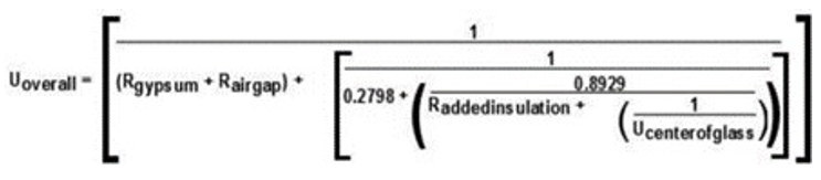
Aluminum with Thermal Break (Equation 3-2)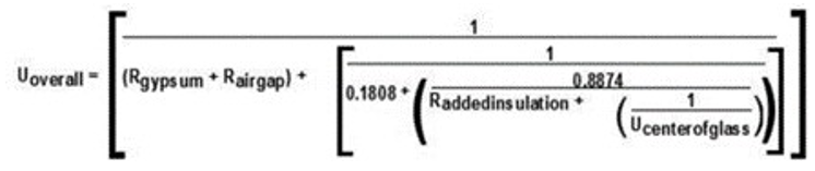
Structural Glazing (Equation 3-3)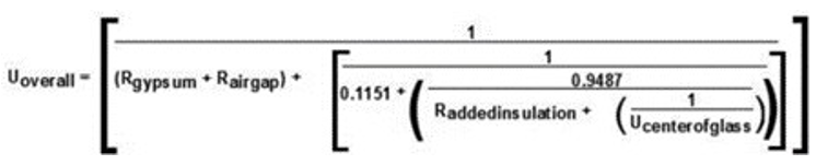
|
|
|
RATED R-VALUE OF INSULATION BETWEEN FRAMING MEMBERS |
||||||||
|---|---|---|---|---|---|---|---|---|---|---|
|
NONE |
R-4 |
R-7 |
R-10 |
R-15 |
R-20 |
R-25 |
R-30 |
|||
|
FRAME TYPE |
SPANDREL PANEL |
|
A |
B |
C |
D |
E |
F |
G |
H |
|
Aluminum without Thermal Break |
Single glass pane, stone or metal panel |
1 |
0.360 |
0.242 |
0.222 |
0.212 |
0.203 |
0.198 |
0.195 |
0.193 |
|
Double glass with no low-e coatings |
2 |
0.297 |
0.233 |
0.218 |
0.209 |
0.202 |
0.197 |
0.194 |
0.192 |
|
|
Triple or low-e glass |
3 |
0.267 |
0.226 |
0.214 |
0.207 |
0.200 |
0.196 |
0.194 |
0.192 |
|
|
Aluminum with Thermal Break |
Single glass pane, stone or metal panel |
4 |
0.350 |
0.211 |
0.186 |
0.173 |
0.162 |
0.155 |
0.151 |
0.149 |
|
Double glass with no low-e coatings |
5 |
0.278 |
0.200 |
0.180 |
0.170 |
0.160 |
0.154 |
0.151 |
0.148 |
|
|
Triple or low-e glass |
6 |
0.241 |
0.191 |
0.176 |
0.167 |
0.159 |
0.153 |
0.150 |
0.148 |
|
|
Structural Glazing |
Single glass pane, stone or metal panel |
7 |
0.354 |
0.195 |
0.163 |
0.147 |
0.132 |
0.123 |
0.118 |
0.114 |
|
Double glass with no low-e coatings |
8 |
0.274 |
0.180 |
0.156 |
0.142 |
0.129 |
0.122 |
0.117 |
0.114 |
|
|
Triple or low-e glass |
9 |
0.231 |
0.169 |
0.150 |
0.138 |
0.127 |
0.121 |
0.116 |
0.113 |
|
|
No Framing, or Insulation is Continuous |
Single glass pane, stone or metal panel |
10 |
0.360 |
0.148 |
0.102 |
0.078 |
0.056 |
0.044 |
0.036 |
0.031 |
|
Double glass with no low-e coatings |
11 |
0.297 |
0.136 |
0.097 |
0.075 |
0.054 |
0.043 |
0.035 |
0.030 |
|
|
Triple or low-e glass |
12 |
0.267 |
0.129 |
0.093 |
0.073 |
0.053 |
0.042 |
0.035 |
0.030 |
|
C303.2 Installation. Materials, systems and equipment shall be installed in accordance with the manufacturer’s instructions and the International Building Code or International Residential Code, as applicable.
C303.2.1 Protection of exposed foundation insulation. Insulation applied to the exterior of basement walls, crawlspace walls and the perimeter of slab-on-grade floors shall have a rigid, opaque and weather-resistant protective covering to prevent the degradation of the insulation’s thermal performance. The protective covering shall cover the exposed exterior insulation and extend not less than 6 inches (153 mm) below grade.
C303.2.2 Multiple layers of continuous insulation. Where two or more layers of continuous insulation board are used in a construction assembly, the continuous insulation boards shall be installed in accordance with Section C303.2. Where the continuous insulation board manufacturer’s instructions do not address installation of two or more layers, the edge joints between each layer of continuous insulation boards shall be staggered.
CHAPTER 4 [CE]
COMMERCIAL ENERGY EFFICIENCY
|
The following are amendments to the identified sections listed in WAC 51-11C-40000 to WAC 51-11C-41200. Amendments either add new sections or replace the section in their entirety. All other sections remain as stated in WAC 51-11C. |
SECTION C401 GENERAL
C401.1 Scope. The provisions in this chapter are applicable to commercial buildings and their building sites.
C401.2 Application. Commercial buildings shall comply with the fossil fuel compliance path according to Section C401.3, or with one of the following:
1. Prescriptive path. The prescriptive compliance option requires compliance with all of Chapter 4, other than Sections C401.3, C401.5, and C407.
2. Total building performance path. The total building performance option requires compliance with Section C407.
3. Appendix F is not adopted by the City of Shoreline.
4. Target Performance Path. The requirements of Section C401.5.
C401.2.1 Application to existing buildings. Additions, alterations, repairs, and changes of space conditioning, occupancy, or use to existing buildings shall comply with Chapter 5.
C401.2.2 Application to process equipment. Energy using equipment used by a manufacturing, industrial, or commercial process other than for conditioning spaces or maintaining comfort and amenities for the occupants shall comply with Section C401.3 Item 2, C403.3.2, Tables C403.3.2(1) through (16) inclusive, Sections C403.3.4.1 through C403.3.4.3, C403.7.7, C403.9.2.1, C403.10.3, C403.11.2, C403.11.3, C404.2, C404.6, C404.13, C405.8, C410, and C412.
C401.3 Fossil fuel compliance path. Buildings complying with the fossil fuel compliance path shall comply with the prescriptive compliance path of this code as defined in Item 1 of Section C401.2, and as modified by this Section C401.3.
C401.3.1 Modification of code requirements. For use of this compliance path only, the following changes shall be made to this code:
1. Section C403.1.4 – Space heating. Strike the phrase “...or fossil fuel combustion...” from the first sentence of Section C403.1.4.
2. Section C404.2.1 – Service water heating. Revise the first sentence of Section C404.2.1 to read: “Service hot water shall be provided by fossil fuel water heating equipment, electric air-source heat pump water heating equipment, electric resistance water heating equipment, or a combination of these equipment types meeting the requirements of this section.”
3. Reserved.
4. Table C406.2(1) – Efficiency measure credits. Use Table C406.2(2) credit values in place of Table C406.2(1) credit values.
C401.3.2 Fossil fuel equipment. Fossil fuel combustion appliances are permitted for HVAC heating, and shall comply with the applicable efficiency standards referenced in Section C403.3.3.2. Fossil fuel combustion appliances are permitted for service water heating, and shall comply with applicable efficiency standards referenced in Table C404.2.
C401.3.3 Additional efficiency credits. The number of additional efficiency credits required by Table C406.1 shall be increased by the number required in Table C401.3.3, modified as permitted in this section, and is in addition to the energy efficiency credits and load management credits required by Section C406.
EXCEPTION: The required number of space heating additional efficiency credits are permitted to be reduced in the following instances:
1. Low energy spaces in accordance with Section C402.1.1.1 and equipment buildings in accordance with Section C402.1.2 that are served by space heating systems shall comply with sufficient measures from Table C406.2(1) or Table C406.2(2) to achieve a minimum of 50 percent of the efficiency credits required for new construction by Table C401.3.3, modified as permitted in this section.
2. Building additions that have less than 1,000 square feet of conditioned floor area and that comply with sufficient measures from Table C406.2(1) or Table C406.2(2) to achieve a minimum of 50 percent of the additional efficiency credits required for additions by Table C401.3.3, modified as permitted in this section.
3. Semi-heated spaces in accordance with Section C402.1.1.2 that comply with sufficient measures from Table C406.2(1) or Table C406.2(2) to achieve a minimum of 50 percent of the additional efficiency credits required by Table C401.3.3, modified as permitted in this section.
4. Unconditioned spaces, open parking garages and unconditioned enclosed parking garages are not required to achieve the additional efficiency credits for space heating required by Table C401.3.3.
|
Measure Title |
Applicable Section |
R-1 |
R-2 |
B |
E |
M |
All other |
|---|---|---|---|---|---|---|---|
|
New building – Additional efficiency credits required for space heating systems using the fossil fuel pathway |
C401.3.3.1 |
7 |
24 |
101 |
38 |
111 |
56 |
|
New building – Additional efficiency credits required for service water heating systems using the fossil fuel pathway |
C401.3.3.2 |
198 |
212 |
27 |
17 |
79 |
107 |
|
Building additions – Additional efficiency credits required for space heating systems using the fossil fuel pathway |
C401.3.3.1 |
4 |
12 |
51 |
19 |
56 |
28 |
|
Building additions – Additional efficiency credits required for service water heating systems using the fossil fuel pathway |
C401.3.3.1 |
99 |
106 |
14 |
9 |
40 |
54 |
C401.3.3.1 HVAC credit modification. The number of HVAC heating energy efficiency credits required by Table C401.3.3 is permitted to be decreased according to the following equation:
CR = A x (C - B)/D
Where:
|
CR |
= |
additional credits required, rounded to the nearest whole number |
|
A |
= |
baseline HVAC heating credits from Table C401.3.3 |
|
B |
= |
installed fossil fuel or electric resistance space heating capacity in kBTU/h of space heating appliances that comply with any of the exceptions to Section C403.1.4 |
|
C |
= |
total installed fossil fuel or electric resistance space heating capacity in kBTU/h of all HVAC heating appliances |
|
D |
= |
total capacity in kBTU/h of all types of space heating appliances |
C401.3.3.2 Service water heating credit modification. The number of service water heating energy efficiency credits required by Table C401.3.3 is permitted to be decreased according to the following equation:
CR = A x (C - B)/D
Where:
|
CR |
= |
additional credits required, rounded to the nearest whole number |
|
A |
= |
baseline service water heating credits from Table C401.3.3 |
|
B |
= |
installed service water heating appliances capacity in kBTU/h of service water heating appliances that comply with exceptions 1, 2, 5, 7, or 8 to Section C404.2.1 |
|
C |
= |
total installed fossil fuel or electric resistance service water heating capacity in kBTU/h of all service water heating appliances, except the supplemental capacity permitted by Section C404.2.1.4 |
|
D |
= |
total capacity in kBTU/h of all types of service water heating appliances, except the supplemental capacity permitted by Section C404.2.1.4 |
C401.3.4 Renewable energy credit limit. No more than 80 percent of the efficiency credits required by Sections C401.3.3.1 and C401.3.3.2 are permitted to be Renewable Energy credits defined in Section C406.2.5.
C401.3.5 Discrete area-weighted project compliance. In addition to the area-weighted credit requirements in Section C406.1.2, where a building includes multiple occupancies, the additional required credits per Table C401.3.3 shall be determined separately for each occupancy group. Additional required credits shall be prorated on an area-weighted basis for each occupancy group in the same manner as required project credits per Section C406.1.
1. Where a single space heating or service water heating system serves multiple occupancies, the number of additional required credits shall be prorated on an area-weighted basis for each occupancy served.
2. Additional required credits for envelope systems shall be prorated on an area-weighted basis for all occupancies.
3. Occupancies are permitted to be subdivided into discrete areas, with required and achieved credits for each area prorated on an area-weighted basis as required for the occupancy group.
C401.3.6 Electrification readiness. Additionally, the following provisions shall be required for new construction for each fossil fuel space heating or service water heating appliance installed:
1. Provide a spare electrical branch circuit conduit to the location of a future replacement heat pump appliance to support an equivalent heating capacity.
2. Provide spare electrical service entrance conduits for the purpose of upgrading the main electrical service to support all heat pump appliances throughout the building.
3. The main electrical room has sufficient space to accommodate increasing the main electrical service’s size to support all heat pump appliances throughout the building.
4. Additional accommodations for the equipment comprised of transformer(s) and other equipment necessary to support an electrical service upgrade. These accommodations shall include adequate space on the site. If the equipment is located in a transformer vault, that vault must include not only the space to support electrical service upgrade but also include accommodations for additional cooling for larger transformer(s).
C401.4 Thermal envelope certificate. A permanent thermal envelope certificate shall be completed by an approved party. Such certificate shall be posted on a wall in the space where the space conditioning equipment is located, a utility room or other approved location. If located on an electrical panel, the certificate shall not cover or obstruct the visibility of the circuit directory label, service disconnect label, or other required labels. A copy of the certificate shall also be included in the construction files for the project. The certificate shall include:
1. R-values of insulation installed in or on ceilings, roofs, walls, foundations and slabs, crawlspace walls and floors, and ducts outside conditioned spaces.
2. U-factors and solar heat gain coefficients (SHGC) of fenestration.
3. Results from any building envelope air leakage testing performed on the building.
Where there is more than one value for any component of the building envelope, the certificate shall indicate the area-weighted average value where available. If the area-weighted average is not available, the certificate shall list each value that applies to 10 percent or more of the total component area.
C401.5 Target Performance Path.
C401.5.1 Scope. Buildings of the following occupancy types, including their initial tenant improvements, are permitted to conform to the Target Performance Path as described in this section and are not required to comply with Shoreline Energy Code requirements other than the mandatory measures listed in Section C401.5.3.
1. Group B office.
2. Group B medical office.
3. Group R-2 multi-family over three stories.
4. Group S-1 & S-2 warehouse (non-refrigerated).
5. Group E school.
6. Group M retail.
7. Group I-2 hospital.
8. Other occupancy type, where specific permission is granted by the code official. Any such permission, if granted, shall be made on the basis of an energy use target approved by the code official for that occupancy based on the best-performing local examples of that occupancy, adjusted to recognize the additional stringency of the current energy code.
9. Mixed use: A mixed use building is any building containing more than one of the occupancies listed in 1 through 8 above.
C401.5.1.1 Increased building performance factor. Each building conforming to this section is permitted to utilize a building performance factor (BPF) 1.12 times the BPF in Table C407.3(2).
C401.5.1.2 Site Energy Performance Target. Each building conforming to this section must demonstrate compliance with the Site energy performance factor per Table C407.3(3) as part of the permit review. Documentation of compliance with Site Energy Performance Target during the performance period is not required.
C401.5.2.1 Data Center Energy. Anticipated total data center energy use is permitted to be added to the overall building energy usage target in accordance with this section. The anticipated IT energy usage shall be multiplied by a factor of 1.45 to determine the anticipated total data center energy use. The IT energy usage shall be separately sub-metered in a secure manner approved by the code official and automatically exported to the code official showing daily, monthly and annual totals during the operational energy use demonstration period set forth in Section C401.5.6. Actual IT energy shall be adjusted in accordance with Section C401.5.7.
C401.5.3 Mandatory measures. Buildings using the Target Performance Path shall:
1. Not exceed the building performance factor (BPF) permitted by Section C401.5.1.1;
2. Not use fossil fuel combustion or electric resistance appliances for purposes of space heating or domestic water heating, except as permitted by the exceptions to Section C403.1.4;
3. Have a building envelope with a Proposed Total UA no greater than the Allowable Total UA as determined by Section C407.3.1; and
4. Comply with the mandatory measures listed in Table C407.2.
C401.5.4 Energy modeling methodology. Energy use shall be modeled according to the requirements of Section C407, Total Building Performance:
Schedules, internal loads and other assumptions related to the operation of the building are permitted to be developed at the discretion of the design team and the energy modeler. For occupancy types listed in Appendix B of this code, where any of the following operating loads or schedules of operating hours used in modeling calculations is less than 80 percent of that listed in Appendix B, or where the occupant density in square feet per occupant is more than 120 percent of that listed in Appendix B, such deviations shall be clearly documented in the final analysis report and are subject to approval by the code official.
1. Occupant density and schedule.
2. Lighting operation schedule.
3. Receptacle loads and schedule.
4. Elevator and escalator schedule.
5. Water heating quantity and schedule.
In addition to documenting modeling assumptions, the application documentation required by Section G1.3.2 of ASHRAE 90.1, Appendix G, shall include the following:
1. Summary of principal building characteristics that are above or below prescriptive energy code requirements.
2. Sensitivity analysis of principal internal load and other building operational assumptions that demonstrate a range of expected energy performance in the context of typical meteorological year (TMY) conditions. The following sensitivity analyses shall be reported, in tabular format:
2.1. Occupant density +/- 20 percent (except residential occupancies).
2.2. Lighting Power Density +/- 20 percent.
2.3. Miscellaneous Load Power Density +/- 20 percent.
2.4. Infiltration Rates +/- 20 percent.
2.5. Temperature Setpoints +/- 2 degrees F.
|
Allowable EUI: 45 kBTU/ft2 |
|
|
|
Predicted EUI: 40 kBTU/ft2 |
|
|
|
Input |
EUI (Low Range) |
EUI (High Range) |
|
Occupant Density |
35 |
42 |
|
Lighting Power Density |
38 |
41 |
|
Misc. Load Power Density |
35 |
45 |
|
Infiltration |
38 |
44 |
|
Temperature Setpoints |
36 |
48 |
C401.5.5 Energy modeler qualifications. Energy models shall be created only by persons qualified by education and training to perform such work and who have at least two years’ experience modeling buildings of similar scale and complexity. The modeling documentation submitted shall be signed either by a licensed professional engineer who is qualified by training and experience to perform energy modeling or by an individual with an active certification from ASHRAE as a Building Energy Modeling Professional (BEMP).
C401.5.6 Demonstration of operating energy use. Metered energy data shall be supplied directly via automated reporting from utilities to the code official using Portfolio Manager, and adjusted for the percentage of the conditioned floor area intended for occupancy that is occupied during the recording period. While more than 95 percent occupied, the building shall be considered fully occupied. While no less than 85 percent occupied, the building shall operate at or below its assigned building performance factor established in Section C401.5.2 or Item 8 of Section C401.5.1 for any recording period of 12 consecutive months that is completed within three years of the date of the Certificate of Occupancy, as adjusted under this Section C401.5. The owner shall notify the code official when this 12-month period has been successfully completed.
C401.5.6.1 Extension of demonstration period. For good cause, including conditions where less than 75 percent of the building is occupied, the code official may extend the three-year period for one additional year, but in no case for more than three additional one-year periods. If the building is not at least 75 percent occupied after three additional one-year periods, the code official shall evaluate compliance with Section C401.5.6 based on the most recent one-year period and adjusted for the actual occupancy rate during that period.
C401.5.7 Adjustment for data center energy usage. Where data center IT energy usage during the demonstration period, multiplied by a factor of 1.45, is higher than the total data center energy use as calculated according to Section C401.5.2.1, that additional energy shall be added to the total allowable energy use. Where data center IT energy use, multiplied by a factor of 1.45, is lower than the total data center energy use as calculated according to Section C401.5.2.1, that shortfall shall be subtracted from the total allowable energy use.
C401.5.8 Adjustment for change in occupancy. When the occupancy of the building or a portion of the building changes from that assumed in the permit submittal, the assigned energy performance target shall be adjusted to reflect the new occupancy. If the new occupancy is not listed in Section C401.5.2, either the code official shall assign it an energy use target based on the best-performing local examples of that occupancy type, or a metering system shall be provided that excludes the energy loads for the additional occupancy.
C401.5.9 Adjustment for unusually cold years. If the heating degree days (HDD) recorded by the National Weather Service for the Seattle-Tacoma International Airport exceeds 4,885 HDD for the 12-month demonstration period (4 percent above the average 4,697 HDD at 65°F base), the assigned energy performance target is permitted to be increased by 1 percent for that period.
C401.5.10 Adjustment for retail operating hours. If the annual number of hours that a retail occupancy is open to the public during the 12-month recording period exceeds the hours assumed in the energy model by more than 4 percent, the annual energy use target for the retail space use only is permitted to be increased by 1 percent for each 4 percent increase in such hours. This claim shall be documented by publicly available published hours of operation.
C401.5.11 Adjustment for commercial kitchens and other large process loads. Where the building includes a commercial kitchen, commercial laundry, hospital central sterile processing facility, or similar large process load, and where approved by the code official, the energy use of the process equipment and exhaust fans and relief air fans and air tempering associated with the use of that equipment is permitted to be separately sub-metered and subtracted from the overall building energy usage. Energy use of typical HVAC, lighting, and miscellaneous electrical loads within such spaces shall not be included in this adjustment. An approved plan shall be submitted with the permit documents detailing how the sub-metered process load energy will be automatically deducted from the total building energy use and the adjusted total reported to the code official.
C401.5.12 Financial security. The applicant shall provide a financial security to be used as a penalty for failing to achieve an operating energy use lower than the building’s energy use target according to Section C401.5.6. The penalty shall be administered as provided in Section C110, except that the amount of the penalty shall be determined using Table C401.5.13 and not Section C107. The financial security shall be submitted to and approved by the code official prior to issuance of the building’s Certificate of Occupancy. The financial security requirement shall be fulfilled by one of the following methods:
1. An irrevocable letter of credit from a financial institution authorized to do business in Shoreline, in an amount equal to $4.00 per square foot of gross conditioned floor area.
2. A bond secured by the applicant to ensure compliance with this section, in an amount equal to $4.00 per square foot of gross conditioned floor area.
3. A binding pledge that within 3 years of receipt of the Certificate of Occupancy, adjusted as allowed under Section C401.5.6.1, the applicant will comply with the requirements of this section.
3.1. A binding pledge pursuant to item 3 of this subsection shall be recorded as a covenant in the land records of King County between the applicant and The City of Shoreline in a form that is satisfactory to the Shoreline City Attorney. The covenant shall bind the applicant and any successors in title to pay any fines levied pursuant to this section. A lien will be placed on the property in cases of non-payment.
If the owner provides evidence that the building has operated at or below its target energy performance level as provided in Section C401.5.6, the financial security provided by the applicant shall be returned to the applicant, or the pledge and covenant shall be released, and the applicant will have no further obligations under this section.
C401.5.13 Procedure for non-compliance. If the owner fails to provide evidence that the building has operated as required under Section C401.5.6, the code official shall, as applicable, either:
1. Draw down on a financial security provided in the form of an irrevocable letter of credit or a bond, in whole, or in part; or
2. Levy a fine against an applicant that provided a financial security in the form of a binding pledge as set forth in Section C401.5.12(3). The fine shall be issued as a civil penalty.
The amount of the fine levied or the amount drawn down from a financial security shall be determined according to Table C401.5.13.
|
Energy use exceeding target |
Amount of fine or draw-down from financial security, per square foot of gross conditioned floor area |
Maximum reimbursement per square foot of gross conditioned floor area for work approved under Section C401.5.12 |
|---|---|---|
|
Less than 10% |
$1.00 |
$0.50 |
|
10% to less than 20% |
$2.00 |
$1.00 |
|
20% to less than 30% |
$3.00 |
$1.50 |
|
30% or greater |
$4.00 |
$2.00 |
C401.5.14 Reimbursements. Where a financial security has been drawn down pursuant to item 1 in Section C401.5.13, or a fine has been levied pursuant to item 2 in Section C401.5.13, the code official shall reimburse the owner for documented expenses incurred to lower the operating energy use of the building, including commissioning, repairs or improvements to the existing energy-consuming systems, or provision of additional energy efficiency measures, up to the maximum reimbursement amounts listed in Table C401.5.13. Such expenditures shall be approved in advance by the code official, and the work shall be fully completed within one year of the date when a financial security has been drawn down pursuant to item 1 in Section C401.5.13, or a fine has been levied pursuant to item 2 in Section C401.5.13.
SECTION C402 BUILDING ENVELOPE REQUIREMENTS
C402.1 General. Building thermal envelope assemblies for buildings that are intended to comply with the code on a prescriptive basis, in accordance with the compliance path described in Item 1 of Section C401.2, shall comply with the following:
1. The opaque portions of the building thermal envelope shall comply with the specific insulation requirements of Section C402.2 and the thermal requirements of either the R-value based method of Section C402.1.3, the U-, C- and F-factor based method of Section C402.1.4, or the component performance alternative of Section C402.1.5.
2. Fenestration in the building envelope assemblies shall comply with Section C402.4, or the component performance alternative of Section C402.1.5.
3. Air leakage of building envelope assemblies shall comply with Section C402.5.
C402.1.1 Low energy buildings, semi-heated buildings and greenhouses. Low energy buildings shall comply with Section C402.1.1.1. Semi-heated buildings and spaces shall comply with Section C402.1.1.2. Greenhouses shall comply with Section C402.1.1.3.
C402.1.1.1 Low energy buildings. The following buildings, or enclosed portions thereof, separated from the remainder of the building by building thermal envelope assemblies complying with this code shall be exempt from all thermal envelope provision of this code:
1. Those that are heated and/or cooled with a peak design rate of energy usage less than 3.4 Btu/h × ft2 (10.7 W/m2) or 1.0 watt/ft2 (10.7 W/m2) of floor area for space conditioning purposes.
2. Those that do not contain conditioned space.
3. Unstaffed equipment shelters or cabinets used solely for personal wireless service facilities.
C402.1.1.2 Semi-heated buildings and spaces. The building envelope of semi-heated buildings, or portions thereof, shall comply with the same requirements as that for conditioned spaces in Section C402, except as modified by this section. The total installed output capacity of mechanical space conditioning systems serving a semi-heated building or space shall comply with Section C202, except as modified by this section. Building envelope assemblies separating conditioned space from semi-heated space shall comply with exterior envelope insulation requirements. Semi-heated spaces are not required to comply with the opaque wall insulation provisions of Section C402.2.2 for walls that separate semi-heated spaces from the exterior or low energy spaces. Fenestration that forms part of the building thermal envelope enclosing semi-heated spaces shall comply with Section C402.4. Semi-heated spaces shall be calculated separately from other conditioned spaces for compliance purposes.
Opaque walls in semi-heated spaces shall be calculated as fully code compliant opaque walls for both the target and proposed for the Target UA calculations for Component Performance compliance per Section C402.1.5, and for the Baseline Building Design for Total Building Performance compliance per Section C407. The capacity of heat trace temperature maintenance systems complying with Section C404.7.2 that are provided for freeze protection of piping and equipment only shall not be included in the total installed output capacity of mechanical space conditioning systems.
EXCEPTION: Provided the total installed heating output capacity of mechanical space conditioning does not exceed the criteria for semi-heated space as defined in Section C202, a semi-heated building or space is permitted to comply with this section when served by heat pumps without electric resistance back up and connected to a heating only thermostat.
C402.1.1.3 Greenhouses. Greenhouse structures or areas that comply with all of the following shall be exempt from the building envelope requirements of this code:
1. Exterior opaque envelope assemblies complying with Sections C402.2 and C402.4.4.
EXCEPTION: Low energy greenhouses that comply with Section C402.1.1.1.
2. Interior partition building thermal envelope assemblies that separate the greenhouse from conditioned space complying with Sections C402.2, C402.4.3 and C402.4.4.
3. Fenestration assemblies complying with the thermal envelope requirements in Table C402.1.1.3. The U-factor for the skylight shall be for the roof assembly or a roof that includes the assembly and an internal curtain system.
EXCEPTION: Unheated greenhouses.
4. No mechanical cooling is provided.
5. For heated greenhouses, heating is provided by a radiant heating system, a condensing natural gas-fired or condensing propane-fired heating system, or a heat pump with cooling capacity permanently disabled as preapproved by the jurisdiction.
|
Component |
U-Factor BTU/h-ft2-°F |
|---|---|
|
Skylights |
0.5 |
|
Vertical fenestration |
0.6 |
C402.1.2 Equipment buildings. Buildings that comply with all of the following shall be exempt from the building thermal envelope provisions of this code:
1. Are separate buildings with floor area no more than 500 square feet (50 m2).
2. Are intended to house electric equipment with installed equipment power totaling at least 7 watts per square foot (75 W/m2) and not intended for human occupancy.
3. Are served by mechanical cooling and heating systems sized in accordance with Sections C403.1.2 and C403.3.1.
4. Have a heating system capacity not greater than 17,000 Btu/hr (5 kW) and a heating thermostat set point that is restricted to not more than 50°F (10°C).
5. Have an average wall and roof U-factor less than 0.200.
EXCEPTION: Where the cooling and heating system is a heat pump, the heating capacity is allowed to exceed 17,000 Btu/h provided the heat pump cooling efficiency is at least 15 percent better than the requirements in Tables C403.3.2(2) and C403.3.2(14).
C402.1.2.1 Standalone elevator hoistways. Elevator hoistways that comply with all of the following shall be exempt from the building thermal envelope and envelope air barrier provisions of this code:
1. Are separate from any other conditioned spaces in the building (do not serve or open into any conditioned, semi-heated or indirectly conditioned space).
2. Have heating and/or cooling equipment sized only to serve the expected elevator loads with thermostat setpoints restricted to heating to no higher than 40°F and cooling to no lower than 95°F.
3. Have an area weighted average wall, roof and floor (where applicable) U-factor of less than or equal to 0.20. Calculations must include any floor-slab-edges that penetrate the hoistway and thus are considered part of the above-grade walls.
|
CLIMATE ZONE |
5 AND MARINE 4 |
|
|---|---|---|
|
All Other |
Group R |
|
|
Roofs |
||
|
Insulation entirely above deck |
R-38ci |
R-38ci |
|
Metal buildingsb |
R-25 + R-22 LS |
R-25 + R-22 LS |
|
Attic and other |
R-49 |
R-49 |
|
Walls, Above Gradei |
||
|
Massh |
Exterior: R-16 c.i. Interior: R-13 + R-6 ci wood stud, or R-13 + R-10 ci metal stud |
Exterior: R-16 c.i. Interior: R-13 + R-6 ci wood stud, or R-13 + R-10 ci metal stud |
|
Mass transfer deck slab edge |
N/R |
N/R |
|
Metal buildings |
R-13 + R-14ci |
R-13 + R-14ci |
|
Steel framed |
R-13 + R-10ci |
R-19 + R-8.5ci |
|
Wood framed and other |
R-13 + R-7.5ci std or R-20 + R-3.8ci std or R-25 std |
R-13 + R-7.5ci std or R-20 + R-3.8ci std or R-25 std |
|
Walls, Below Grade |
||
|
Below-grade walld,h |
Exterior: R-10 ci Interior: R-19 wood stud, or R-13 + R-6 ci metal stud |
Exterior: R-10 ci Interior: R-19 wood stud, or R-13 + R-6 ci metal stud |
|
Floors |
||
|
Massf |
R-30ci |
R-30ci |
|
Joist/framing |
Steel frame: R-38 +R-10 ci Wood frame: R-38 |
Steel frame: R-38 +R-10 ci Wood frame: R-38 |
|
Slab-on-Grade Floors |
||
|
Unheated slabs |
R-10 for 24" below |
R-10 for 24" below |
|
Heated slabs |
R-10 perimeter & under entire slab |
R-10 perimeter & under entire slab |
For SI: 1 inch = 25.4 mm. ci = Continuous insulation. NR = No requirement.
LS = Liner system—A continuous membrane installed below the purlins and uninterrupted by framing members. Uncompressed, unfaced insulation rests on top of the membrane between the purlins.
a Assembly descriptions can be found in Chapter 2 and Appendix A.
b Where using R-value compliance method, a thermal spacer block with minimum thickness of 1/2-inch and minimum R-value of R-3.5 shall be provided, otherwise use the U-factor compliance method in Table C402.1.4.
c (Reserved)
d Where heated slabs are below grade, they shall comply with the insulation requirements for heated slabs.
e (Reserved)
f “Mass floors” shall include floors weighing not less than:
1. 35 pounds per square foot of floor surface area; or
2. 25 pounds per square foot of floor surface area where the material weight is not more than 120 pounds per cubic foot.
g Component performance in accordance with Section C402.1.5 shall be required for buildings with a mass transfer deck slab.
h Peripheral edges of intermediate concrete floors are included in the above-grade mass wall category and therefore must be insulated as above-grade mass walls unless they meet the definition of Mass Transfer Deck Slab Edge. The area of the peripheral edges of concrete floors shall be defined as the thickness of the slab multiplied by the perimeter length of the edge condition. See Table A103.3.7.2 for typical default U-factors for above-grade slab edges and footnote c for typical conditions of above-grade slab edges.
i Where the total area of through-wall mechanical equipment is greater than 1 percent of the opaque above-grade wall area, use of the R-value method is not permitted. See Section C402.1.4.3.
j For roof, wall or floor assemblies where the proposed assembly would not be continuous insulation, alternate nominal R-value compliance options for assemblies with isolated metal fasteners that penetrate otherwise continuous insulation are as shown in columns B and C of Table C402.1.3(i):
|
Column A |
Column B |
Column C |
|---|---|---|
|
Assemblies with continuous insulation (see definition) |
Alternate option for assemblies with metal penetrations, greater than 0.04% but less than 0.08% |
Alternate option for assemblies with metal penetrations, greater than or equal to 0.08% but less than 0.12% |
|
R-9.5ci |
R-11.9ci |
R-13ci |
|
R-11.4ci |
R-14.3ci |
R-15.7ci |
|
R-13.3ci |
R-16.6ci |
R-18.3ci |
|
R-15.2ci |
R-19ci |
R-21ci |
|
R-30ci |
R-38ci |
R-42ci |
|
R-38ci |
R-48ci |
R-53ci |
|
R-13 + R-7.5ci |
R-13 + R-9.4ci |
R-13 + R-10.3ci |
|
R-13 + R-10ci |
R-13 + R-12.5ci |
R-13 + R-13.8ci |
|
R-13 + R-12.5ci |
R-13 + R-15.6ci |
R-13 + R-17.2ci |
|
R-13 + R-13ci |
R-13 + R-16.3ci |
R-13 + R-17.9ci |
|
R-19 + R-8.5ci |
R-19 + R-10.6ci |
R-19 + R-11.7ci |
|
R-19 + R-14ci |
R-19 + R-17.5ci |
R-19 + R-19.2ci |
|
R-19 + R-16ci |
R-19 + R-20ci |
R-19 + R-22ci |
|
R-20 + R-3.8ci |
R-20 + R-4.8ci |
R-20 + R-5.3ci |
|
R-21 + R-5ci |
R-21 + R-6.3ci |
R-21 + R-6.9ci |
Notes for Table C402.1.3(i)
These alternate nominal R-value compliance options are allowed for projects complying with all of the following:
1a. The ratio of the cross-sectional area, as measured in the plane of the surface, of metal penetrations of otherwise continuous insulation to the opaque surface area of the assembly is greater than 0.0004 (0.04%), but less than 0.0008 (0.08%), for use of Column B equivalents, and greater than or equal to 0.008 (0.08%), but less than 0.0012 (0.12%), for use of Column C equivalents.
1b. Where all metal penetrations are stainless steel, Column B is permitted to be used for penetrations greater than 0.12%, but less than 0.24% of opaque surface area, and Column C is permitted to be used for penetrations greater than or equal to 0.24%, but less than 0.48% of opaque surface area.
2. The metal penetrations of otherwise continuous insulation are isolated or discontinuous (e.g., brick ties or other discontinuous metal attachments, offset brackets supporting shelf angles that allow insulation to go between the shelf angle and the primary portions of the wall structure). No continuous metal elements (e.g., metal studs, z-girts, z-channels, shelf angles) penetrate the otherwise continuous portion of the insulation.
3. Building permit drawings shall contain details showing the locations and dimensions of all the metal penetrations (e.g., brick ties or other discontinuous metal attachments, offset brackets, etc.) of otherwise continuous insulation. In addition, calculations shall be provided showing the ratio of the cross-sectional area of metal penetrations of otherwise continuous insulation to the overall opaque wall area.
For other cases where the proposed assembly is not continuous insulation, see Section C402.1.4 for determination of U-factors for assemblies that include metal other than screws and nails.
C402.1.3 Insulation component R-value-based method. Building thermal envelope opaque assemblies shall comply with the requirements of Section C402.2 based on the climate zone specified in Chapter 3. For opaque portions of the building thermal envelope intended to comply on an insulation component R-value basis, the R-values for cavity insulation and continuous insulation shall not be less than that specified in Table C402.1.3. Where cavity insulation is installed in multiple layers, the cavity insulation R-values shall be summed to determine compliance with the cavity insulation R-value requirements. Where continuous insulation is installed in multiple layers, the continuous insulation R-values shall be summed to determine compliance with the continuous insulation R-value requirements. Cavity insulation R-values shall not be used to determine compliance with the continuous insulation R-value requirements in Table C402.1.3. Commercial buildings or portions of commercial buildings enclosing Group R occupancies shall use the R-values from the “Group R” column of Table C402.1.3. Commercial buildings or portions of commercial buildings enclosing occupancies other than Group R shall use the R-values from the “All other” column of Table C402.1.3.
EXCEPTION: For stair and elevator shafts that do not comply with Section C402.1.2.1 and that are located within enclosed garages or other enclosed non-conditioned spaces and without conditioned supply air or cooling or heating appliances rated higher than 2 kW in any shaft, walls enclosing the shafts are permitted to be:
1. Concrete or masonry with minimum R-5 continuous insulation;
2. Metal studs with R-15 cavity insulation and without continuous insulation; or
3. Other assemblies with a maximum U-value of 0.120.
Slab floors, intermediate mass floor edges and elevator pits within shafts using this exception are excluded from envelope insulation requirements. Shaft surfaces using this exception shall not be included in the gross exterior wall area for purposes of maximum fenestration area calculations in Section C402.4.1 component performance calculations in Section C402.1.5, or for the total building performance calculation of Section C407.
C402.1.4 Assembly U-factor, C-factor, or F-factor-based method. Building thermal envelope opaque assemblies shall meet the requirements of Section C402.2 based on the climate zone specified in Chapter 3. Building thermal envelope opaque assemblies intended to comply on an assembly U-, C-, or F-factor basis shall have a U-, C-, or F-factor not greater than that specified in Table C402.1.4. Commercial buildings or portions of commercial buildings enclosing Group R occupancies shall use the U-, C-, or F-factor from the “Group R” column of Table C402.1.4. Commercial buildings or portions of commercial buildings enclosing occupancies other than Group R shall use the U-, C-, or F-factor from the “All other” column of Table C402.1.4. The U-factors for typical construction assemblies are included in Appendix A. These values shall be used for all calculations. Where proposed construction assemblies are not represented in Appendix A, values shall be calculated in accordance with the ASHRAE Handbook—Fundamentals using the framing factors listed in Appendix A where applicable and shall include the thermal bridging effects of framing materials.
C402.1.4.1 Roof/ceiling assembly. The maximum roof/ceiling assembly U-factor shall not exceed that specified in Table C402.1.4 based on construction materials used in the roof/ceiling assembly.
C402.1.4.1.1 Suspended ceilings. Insulation installed on suspended ceilings having removable ceiling tiles shall not be considered part of the assembly U-factor of the roof/ceiling construction.
C402.1.4.1.2 Joints staggered. Continuous insulation board shall be installed not less than two layers, and the edge joints between each layer of insulation shall be staggered, except where insulation tapers to the roof deck at a gutter edge, roof drain, or scupper.
C402.1.4.2 Thermal resistance of cold-formed steel stud walls. U-factors of walls with cold-formed steel studs shall be permitted to be determined either by using the values in Table C402.1.4.2, or in accordance with Equation 4-1:
|
U = 1/[Rs + (ER)] |
(Equation 4-1) |
Where:
|
Rs |
= |
The cumulative R-value of the wall components along the path of heat transfer, excluding the cavity insulation and steel studs. |
|
ER |
= |
The effective R-value of the cavity insulation with steel studs as specified in Table C402.1.4.2. |
C402.1.4.3 Thermal resistance of mechanical equipment penetrations. When the total area of penetrations from through-wall mechanical equipment or equipment listed in Table C403.3.2(4) exceeds 1 percent of the opaque above-grade wall area, the mechanical equipment penetration area shall be calculated as a separate wall assembly with a default U-factor of 0.5. Mechanical system ducts and louvers, including those for supply, exhaust and relief, and for condenser air intake and outlet, are not considered to be mechanical equipment for the purposes of this section.
EXCEPTION: Where mechanical equipment has been tested in accordance with approved testing standards, the mechanical equipment penetration area is permitted to be calculated as a separate wall assembly using the U-factor determined by such test.
|
CLIMATE ZONE |
5 AND MARINE 4 |
|
|---|---|---|
|
All Other |
Group R |
|
|
Roofs |
||
|
Insulation entirely above deck |
U-0.027 |
U-0.027 |
|
Metal buildings |
U-0.027 |
U-0.027 |
|
Attic and other |
U-0.021 |
U-0.021 |
|
Joist or single rafter |
U-0.027 |
U-0.027 |
|
Walls, Above Gradek |
||
|
Massg |
U-0.057 |
U-0.057 |
|
Mass transfer deck slabi |
U-0.20 |
U-0.20 |
|
Slab penetrating thermal envelope wallh |
U-0.10 |
U-0.10 |
|
Metal building |
U-0.050 |
U-0.050 |
|
Steel framed |
U-0.055 |
U-0.055 |
|
Wood framed and other |
U-0.051 |
U-0.051 |
|
Walls, Below Grade |
||
|
Below-grade wallb, g |
U-0.070 |
U-0.070 |
|
Floors |
||
|
Masse |
U-0.031 |
U-0.031 |
|
Joist/framing |
U-0.029 steel joist U-0.025 wood joist |
U-0.029 steel joist U-0.025 wood joist |
|
Concrete column or concrete wall penetrating thermal envelope floorl |
U-0.55 |
U-0.55 |
|
Concrete slab floor directly above an electrical utility vault |
N.R. |
N.R. |
|
Slab-on-Grade Floors |
||
|
Unheated slabs |
F-0.54 |
F-0.54 |
|
Heated slabsc |
F-0.55 |
F-0.55 |
|
Opaque Doors |
||
|
Nonswinging door |
U-0.31 |
U-0.31 |
|
Swinging doorh |
U-0.37 |
U-0.37 |
|
Garage door <14% glazing |
U-0.31 |
U-0.31 |
|
Garage door ≥14% and <50% glazingi |
U-0.34 |
U-0.34 |
a Use of opaque assembly U-factors, C-factors, and F-factors from Appendix A is required unless otherwise allowed by Section C402.1.4.
b (Reserved)
c Heated slab F-factors shall be determined specifically for heated slabs. Unheated slab factors shall not be used.
d (Reserved)
e “Mass floors” shall include floors weighing not less than:
1. 35 pounds per square foot of floor surface area; or
2. 25 pounds per square foot of floor surface area where the material weight is not more than 120 pounds per cubic foot.
f Opaque assembly U-factors based on designs tested in accordance with ASTM C1363 shall be permitted. The R-value of continuous insulation shall be permitted to be added or subtracted from the original test design.
g Peripheral edges of intermediate concrete floors are included in the above-grade mass wall category and therefore must be insulated as above-grade mass walls unless they meet the definition of Mass Transfer Deck Slab. The area of the peripheral edges of concrete floors shall be defined as the thickness of the slab multiplied by the perimeter length of the edge condition. See Table A103.3.7.2 for typical default U-factors for above-grade slab edges and footnote c for typical conditions of above-grade slab edges.
h Swinging door U-factors shall be determined in accordance with NFRC-100.
i Garage doors having a single row of fenestration shall have an assembly U-factor less than or equal to 0.44, provided that the fenestration area is not less than 14 percent and not more than 25 percent of the total door area.
j Component performance in accordance with Section C402.1.5 shall be required for buildings with a mass transfer deck slab. A mass transfer deck, due to its configuration, is not insulated. The table value (U-0.20) shall be used as the baseline value for component performance or total building performance path calculations. For the proposed value, the appropriate value from Table A103.3.7.2 shall be used.
k Through-wall mechanical equipment subject to Section C402.1.4.3 shall be calculated at the U-factor defined in Section C402.1.4.3. The area-weighted U-factor of the wall, including through-wall mechanical equipment, shall not exceed the value in the table.
l Value applies to concrete columns and concrete walls that interrupt mass floor insulation, but not to perimeter walls or columns separating interior conditioned space from exterior space.
|
NOMINAL STUD DEPTH (inches) |
SPACING OF FRAMING (inches) |
CAVITY R-VALUE (insulation) |
CORRECTION FACTOR (Fc) |
EFFECTIVE R-VALUE (ER) (Cavity R-Value × Fc) |
|---|---|---|---|---|
|
3-1/2 |
16 |
13 |
0.46 |
5.98 |
|
15 |
0.43 |
6.45 |
||
|
3-1/2 |
24 |
13 |
0.55 |
7.15 |
|
15 |
0.52 |
7.80 |
||
|
6 |
16 |
19 |
0.37 |
7.03 |
|
|
|
21 |
0.35 |
7.35 |
|
6 |
24 |
19 |
0.45 |
8.55 |
|
|
|
21 |
0.43 |
9.03 |
|
8 |
16 |
25 |
0.31 |
7.75 |
|
|
24 |
25 |
0.38 |
9.50 |
C402.1.5 Component performance alternative. Building envelope values and fenestration areas determined in accordance with Equation 4-2 shall be permitted in lieu of compliance with the U-factors and F-factors in Table C402.1.4 and C402.4 and the maximum allowable fenestration areas in Section C402.4.1.
For buildings with more than one space conditioning category, component performance compliance shall be demonstrated separately for each space conditioning category. Interior partition ceilings, walls, fenestration and floors that separate space conditioning areas shall be applied to the component performance calculations for the space conditioning category with the highest level of space conditioning.
|
Proposed Total UA ≤ Allowable Total UA |
(Equation 4-2) |
Where:
|
Proposed Total UA |
= |
UA-glaz-prop + UA sky-prop + UA-opaque-prop + FL-slab-prop |
|
Allowable Total UA |
= |
UA-glaz-allow + UA-glaz-excess + UA sky-allow + UA-sky-excess + UA-opaque-allow + FL-slab-allow |
|
UA-glaz-prop |
= |
Sum of (proposed U-value × proposed area) for each distinct vertical fenestration type, up to code maximum area |
|
UA-sky-prop |
= |
Sum of (proposed U-value × proposed area) for each distinct skylight type, up to the code maximum area |
|
UA-opaque-prop |
= |
Sum of (proposed U-value × proposed area) for each distinct opaque thermal envelope type |
|
FL-slab-prop |
= |
Sum of (proposed F-value × proposed length) for each distinct slab on grade perimeter assembly |
|
UA-glaz-allow |
= |
Sum of (code maximum vertical fenestration U-value from Table C402.4, or Section C402.4.1.1.2 if applicable, × proposed area) for each distinct vertical fenestration type, not to exceed the code maximum area1 |
|
UA-glaz-excess |
= |
U-value for the proposed wall type from Table C402.42 × vertical fenestration area in excess of the code maximum area |
|
UA-sky-allow |
= |
Sum of (code maximum skylight U-value from Table C402.4 × proposed area) for each distinct skylight type proposed, not to exceed the code maximum area |
|
UA-sky-excess |
= |
U-value for the proposed roof type from Table C402.43 × skylight area in excess of the code maximum area |
|
UA-opaque-allow |
= |
Code maximum opaque envelope U-value from Table C402.1.4 for each opaque door, wall, roof, and floor assembly × proposed area |
|
FL-slab-allow |
= |
Code maximum F-value for each slab-on-grade perimeter assembly × proposed length |
Notes:
1 Where multiple vertical fenestration types are proposed and the code maximum area is exceeded, the U-value shall be the average Table C402.1.4 U-value weighted by the proposed vertical fenestration area of each type.
2 Where multiple wall types are proposed the U-value shall be the average Table C402.1.4 U-value weighted by the proposed above grade wall area of each type.
3 Where multiple roof types are proposed the U-value shall be the average Table C402.1.4 U-value weighted by the proposed roof area of each type.
C402.1.5.1 Component U-factors and F-factors. The U-factors and F-factors for typical construction assemblies are included in Chapter 3 and Appendix A. These values shall be used for all calculations. Where proposed construction assemblies are not represented in Chapter 3 or Appendix A, values shall be calculated in accordance with the ASHRAE Handbook—Fundamentals, using the framing factors listed in Appendix A.
For envelope assemblies containing metal framing, the U-factor shall be determined by one of the following methods:
1. Results of laboratory measurements according to acceptable methods of test.
2. ASHRAE Handbook—Fundamentals where the metal framing is bonded on one or both sides to a metal skin or covering.
3. The zone method as provided in ASHRAE Handbook—Fundamentals.
4. Effective framing/cavity R-values as provided in Appendix A.
When return air ceiling plenums are employed, the roof/ceiling assembly shall:
a. For thermal transmittance purposes, not include the ceiling proper nor the plenum space as part of the assembly; and
b. For gross area purposes, be based upon the interior face of the upper plenum surface.
5. Tables in ASHRAE 90.1 Normative Appendix A.
6. Calculation method for steel-framed walls in accordance with Section C402.1.4.2 and Table C402.1.4.2.
C402.1.5.2 SHGC rate calculations. Fenestration SHGC values for individual components and/or fenestration are permitted to exceed the SHGC values in Table C402.4 and/or the maximum allowable fenestration areas in Section C402.4.1 where the proposed total SHGCxA less than the allowable total SHGCxA as determined by Equation 4-3.
|
Proposed Total SHGCxA ≤ Allowable Total SHGCxA |
(Equation 4-3) |
Where:
|
Proposed Total SHGCxA |
= |
SHGCxA-glaz-prop + SHGCxA-sky-prop |
|
Allowable Total SHGCxA |
= |
SHGCxA-glaz-allow + SHGCxA-sky-allow |
|
SHGCxA-glaz-prop |
= |
Sum of (proposed SHGCx proposed area) for each distinct vertical fenestration type |
|
SHGCxA-sky-prop |
= |
Sum of (proposed SHGCx proposed area) for each distinct skylight type |
|
SHGCxA-glaz-allow |
= |
Sum of (code maximum vertical fenestration SHGC from Table C402.4, or Section C402.4.1.3 if applicable, × proposed area) for each distinct vertical fenestration type, not to exceed the code maximum area |
|
SHGCxA-sky-allow |
= |
Sum of (code maximum skylight SHGC from Table C402.4 × proposed area) for each distinct skylight type, not to exceed the code maximum area |
If the proposed vertical fenestration area does not exceed the Vertical Fenestration Area allowed, the target area for each vertical fenestration type shall equal the proposed area. If the proposed vertical fenestration area exceeds the Vertical Fenestration Area allowed, the target area of each vertical fenestration element shall be reduced in the base envelope design by the same percentage and the net area of each above-grade wall type increased proportionately by the same percentage so that the total vertical fenestration area is exactly equal to the Vertical Fenestration Area allowed.
If the proposed skylight area does not exceed the Allowable Skylight Area from Section C402.4.1, the target area shall equal the proposed area. If the proposed skylight area exceeds the Allowable Skylight Area from Section C402.4.1, the area of each skylight element shall be reduced in the base envelope design by the same percentage and the net area of each roof type increased proportionately by the same percentage so that the total skylight area is exactly equal to the allowed percentage per Section C402.3.1 of the gross roof area.
C402.2 Specific building thermal envelope insulation requirements. Insulation in building thermal envelope opaque assemblies shall comply with Sections C402.2.1 through C402.2.9 and Table C402.1.3.
Where this section refers to installing insulation levels as specified in Section C402.1.3, assemblies complying prescriptively with Section C402.1.4 and buildings complying with Section C402.1.5 are allowed to install alternate levels of insulation so long as the U-factor of the insulated assembly is less than or equal to the U-factor required by the respective path.
C402.2.1 Roof assembly. The minimum thermal resistance (R-value) of the insulating material installed either between the roof framing or continuously on the roof assembly shall be as specified in Table C402.1.3, based on construction materials used in the roof assembly.
EXCEPTIONS:
1. Where tapered insulation is used with insulation entirely above deck, those roof assemblies shall show compliance on a U-factor basis per Section C402.1.4. The effective U-factor shall be determined through the use of Tables A102.2.6(1), A102.2.6(2) and A102.2.6(3).
2. Two layers of insulation are not required where insulation tapers to the roof deck, such as at roof drains. At roof drains, the immediate 24 inch by 24 inch plan area around each roof drain has a minimum insulation requirement of R-13, but otherwise is permitted to be excluded from the roof insulation area-weighted calculations.
C402.2.1.1 Minimum thickness, lowest point. The minimum thickness of above-deck roof insulation at its lowest point, gutter edge, roof drain or scupper, shall be not less than 1 inch (25 mm).
C402.2.1.2 Suspended ceilings. Insulation installed on suspended ceilings having removable ceiling tiles shall not be considered part of the minimum thermal resistance (R-value) of roof insulation in roof/ceiling construction.
C402.2.1.3 Skylight curbs. Skylight curbs shall be insulated to the level of roofs with insulation entirely above deck or R-5, whichever is less.
EXCEPTION: Unit skylight curbs included as a component of a skylight listed and labeled in accordance with NFRC 100 shall not be required to be insulated.
C402.2.1.4 Rooftop HVAC equipment curbs. Structural curbs installed to support rooftop HVAC equipment are allowed to interrupt the above roof insulation. The area under the HVAC equipment inside of the equipment curb shall be insulated to a minimum of R-13 in all locations where there are not roof openings for ductwork. The annular space between the roof opening and the ductwork shall be sealed to maintain the building air barrier. The plan-view area of the HVAC equipment curb shall be excluded from the prescriptive roof insulation requirements or the area-weighted component performance calculations.
C402.2.2 Above-grade walls. The minimum thermal resistance (R-value) of materials installed in the wall cavity between the framing members and continuously on the walls shall be as specified in Table C402.1.3, based on framing type and construction materials used in the wall assembly. The R-value of integral insulation installed in concrete masonry units (CMU) shall not be used in determining compliance with Table C402.1.3 except as otherwise noted in the table. In determining compliance with Table C402.1.4, the use of the U-factor of concrete masonry units with integral insulation shall be permitted.
“Mass walls” where used as a component in the thermal envelope of a building shall comply with one of the following:
1. Weigh not less than 35 psf (170 kg/m2) of wall surface area.
2. Weigh not less than 25 psf (120 kg/m2) of wall surface area where the material weight is not more than 120 pounds per cubic foot (pcf) (1,900 kg/m3).
3. Have a heat capacity exceeding 7 Btu/ft2 × °F (144 kJ/m2 × K).
4. Have a heat capacity exceeding 5 Btu/ft2 × °F (103 kJ/m2 × K) where the material weight is not more than 120 pcf (1900 kg/m3).
C402.2.3 Floors. The thermal properties (component R-values or assembly U- or F-factors) of floor assemblies over outdoor air or unconditioned space shall be as specified in Table C402.1.3 or C402.1.4 based on the construction materials used in the floor assembly. Floor framing cavity insulation or structural slab insulation shall be installed to maintain permanent contact with the underside of the subfloor decking or structural slabs.
“Mass floors” where used as a component of the thermal envelope of a building shall provide one of the following weights:
1. Thirty-five pounds per square foot of floor surface area;
2. Twenty-five pounds per square foot of floor surface area where the material weight is not more than 120 pounds per cubic foot.
EXCEPTIONS:
1. The floor framing cavity insulation or structural slab insulation shall be permitted to be in contact with the top side of sheathing or continuous insulation installed on the bottom side of floor assemblies where combined with insulation that meets or exceeds the minimum R-value in Table C402.1.3 for “Metal framed” or “Wood framed and other” values for “Walls, Above Grade” and extends from the bottom to the top of all perimeter floor framing or floor assembly members.
2. Insulation applied to the underside of concrete floor slabs shall be permitted an air space of not more than 1 inch where it turns up and is in contact with the underside of the floor under walls associated with the building thermal envelope.
C402.2.4 Slabs-on-grade. The minimum thermal resistance (R-value) of the insulation for unheated or heated slab-on-grade floors designed in accordance with the R-value method of Section C402.1.3 shall be as specified in Table C402.1.3.
C402.2.4.1 Insulation installation. Where installed, the perimeter insulation shall be placed on the outside of the foundation or on the inside of the foundation wall. The perimeter insulation shall extend downward from the top of the slab for a minimum distance as shown in the table or to the top of the footing, whichever is less, or downward to not less than the bottom of the slab and then horizontally to the interior or exterior for the total distance shown in the table. Insulation extending away from the building shall be protected by pavement or by a minimum of 10 inches (254 mm) of soil. Where installed, full slab insulation shall be continuous under the entire area of the slab-on-grade floor, except at structural column locations and service penetrations. Insulation required at the heated slab perimeter shall not be required to extend below the bottom of the heated slab and shall be continuous with the full slab insulation.
EXCEPTION: Where the slab-on-grade floor is greater than 24 inches (61 mm) below the finished exterior grade, perimeter insulation is not required.
C402.2.5 Below-grade walls. The R-value of the insulating material installed in, or continuously on, the below-grade walls shall be in accordance with Table C402.1.3. The U-factor or R-value required shall extend to the level of the lowest floor of the conditioned space enclosed by the below-grade wall.
C402.2.6 Insulation of radiant heating systems. Radiant heating system panels, and their associated components that are installed in interior or exterior assemblies shall be insulated to an R-value of not less than R-3.5 on all surfaces not facing the space being heated. Radiant heating system panels that are installed in the building thermal envelope shall be separated from the exterior of the building or unconditioned or exempt spaces by not less than the R-value of insulation installed in the opaque assembly in which they are installed or the assembly shall comply with Section C402.1.4.
EXCEPTION: Heated slabs on grade insulated in accordance with Section C402.2.4.
C402.2.7 Airspaces. Where the R-value of an airspace is used for compliance in accordance with Section C401.2, the airspace shall be enclosed in an unventilated cavity constructed to minimize airflow into and out of the enclosed airspace. Airflow shall be deemed minimized where the enclosed airspace is located on the interior side of the continuous air barrier and is bounded on all sides by building components.
EXCEPTION: The thermal resistance of airspaces located on the exterior side of the continuous air barrier and adjacent to and behind the exterior wall covering material shall be determined in accordance with ASTM C1363 modified with an airflow entering the bottom and exiting the top of the airspace at a minimum air movement rate of not less than 70 mm/sec.
C402.2.8 Above-grade exterior concrete slabs. Above-grade concrete slabs that penetrate the building thermal envelope including, but not limited to, decks and balconies, shall each include a minimum R-10 thermal break, aligned with the primary insulating layer in the adjoining wall assemblies. Stainless steel (but not carbon steel) reinforcing bars are permitted to penetrate the thermal break. If the total building performance path or the component performance alternative in Section C402.1.5 is utilized and the thermal break required by this section is not provided where concrete slabs penetrate the building thermal envelope, the sectional area of the penetration shall be assigned the default U-factors from the “exposed concrete” row of Table A103.3.7.2.
EXCEPTION: Mass transfer deck slabs.
C402.2.9 Vertical fenestration intersection with opaque walls. Vertical fenestration shall comply with Items 1, 2, and 3, as applicable.
1. Where wall assemblies include continuous insulation, the exterior glazing layer of vertical fenestration and any required thermal break in the frame shall each be aligned within 2 inches laterally of either face of the continuous insulation layer.
2. Where wall assemblies do not include continuous insulation, the exterior glazing layer of vertical fenestration and any required thermal break in the frame shall each be aligned within the thickness of the wall insulation layer and not more than 2 inches laterally from the exterior face of the outermost insulation layer.
3. Where the exterior face of the vertical fenestration frame does not extend to the exterior face of the opaque wall rough opening, the exposed exterior portion of the rough opening shall be covered with either a material having an R-value not less than R-3, or with minimum 1.5-inch thickness wood.
C402.3 Reserved.
C402.4 Fenestration. Fenestration shall comply with Sections C402.4 through C402.4.4 and Table C402.4. Daylight responsive controls shall comply with this section and Section C405.2.5.
EXCEPTION:
1. For prescriptive envelope compliance, single-pane glazing is permitted for security purposes and for revolving doors, not to exceed 1 percent of the gross exterior wall area. Where Section C402.1.5, component performance alternative, is used, the single glazing shall be included in the percentage of the total glazing area, U-factor and SHGC requirements.
|
CLIMATE ZONE |
5 AND MARINE 4 |
|
|---|---|---|
|
|
U-factor for Class AW windows rated in accordance with AAMA/CSA101/I.S.2/A440, vertical curtain walls and site-built fenestration productsa |
|
|
Fixedb U-factor |
U-0.34 |
|
|
Operablec U-factor |
U-0.36 |
|
|
Entrance doorsd |
||
|
U-factor |
U-0.60 |
|
|
|
U-factor for all other vertical fenestration |
|
|
Fixed U-factor |
U-0.26 |
|
|
Operable or mulled windows with fixed and operable sections U-factor |
U-0.28 |
|
|
SHGC for all vertical fenestration |
||
|
|
Fixed |
Operable |
|
PF < 0.2 |
0.38 |
0.33 |
|
0.2 ≤ PF < 0.5 |
0.46 |
0.40 |
|
PF ≥ 0.5 |
0.61 |
0.53 |
|
Skylights |
||
|
U-factor |
U-0.45 |
|
|
SHGC |
0.32 |
|
a U-factor and SHGC shall be rated in accordance with NFRC 100.
b “Fixed” includes curtain wall, storefront, picture windows, and other fixed windows.
c “Operable” includes openable fenestration products other than “entrance doors,” and includes only the operable portions of multi-pane assemblies.
d “Entrance door” includes glazed swinging entrance doors and automatic glazed sliding entrance doors. Other doors which are not entrance doors, including manually operated sliding glass doors, are considered “operable.”
e Reserved.
f Fenestration that is entirely within the conditioned space or is between conditioned and other enclosed space is exempt from solar heat gain coefficient requirements and not included in the SHGC calculation.
C402.4.1 Maximum area. The total building vertical fenestration area (not including opaque doors and opaque spandrel panels) shall not exceed 30 percent of the total building gross above-grade wall area. The skylight area shall not exceed 5 percent of the total building gross roof area (skylight-to-roof ratio).
For buildings with more than one space conditioning category, compliance with the maximum allowed window-to-wall ratio and skylight-to-roof ratio shall be demonstrated separately for each space conditioning category. Interior partition ceiling, wall, fenestration and floor areas that separate space conditioning areas shall not be applied to the window-to-wall ratio and skylight-to-roof ratio calculations.
EXCEPTIONS:
1. For vertical fenestration at street level retail or for other occupancies where the Shoreline Land Use Code requires street-level transparency, the vertical fenestration area shall not exceed 75 percent of the area of the street-level wall that faces the street or that adjoins other pedestrian areas used for retail access. For the purposes of this exception, the street-level wall shall be measured from the street-level floor to the interior ceiling level or to 20 feet above floor level, whichever is lowest. When this exception is used, separate calculations shall be performed for these sections of the building envelope, and these values shall not be averaged with any others for compliance purposes. On the street level the 75 percent vertical fenestration area is permitted to be exceeded, if the additional fenestration area is deducted from fenestration allowances from other areas of the building.
2. Accessory occupancy areas that comprise less than 10 percent of the conditioned floor area of any floor are permitted to be included in the primary occupancy of that floor for determination of the allowable fenestration area for that floor.
C402.4.1.1 Vertical fenestration maximum area with high performance alternates. For buildings that comply with Section C402.4.1.1.1 or C402.4.1.1.2, the total building vertical fenestration area is permitted to exceed 30 percent but shall not exceed 40 percent of the total building gross above grade wall area for the purpose of prescriptive compliance with Section C402.1.4.
When determining compliance using the component performance alternative in accordance with Section C402.1.5, the total building vertical fenestration area allowed in Equation 4-2 (UA-glaz-allow) is 40 percent of the above grade wall area for buildings that comply with the vertical fenestration alternates described in this section.
C402.4.1.1.1 Optimized daylighting. All of the following requirements shall be met:
1. Not less than 50 percent of the total conditioned floor area in the building is within a daylight zone that includes daylight responsive controls complying with Section C405.2.5.1.
2. Visible transmittance (VT) of all vertical fenestration in the building is greater than or equal to 1.1 times the required solar heat gain coefficient (SHGC) in accordance with Section C402.4, or 0.50, whichever is greater. It shall be permitted to demonstrate compliance based on the area weighted average VT being greater than or equal to the area weighted average of the minimum VT requirements.
EXCEPTION: Fenestration that is outside the scope of NFRC 200 is not required to comply with Item 2.
C402.4.1.1.2 High-performance fenestration. All of the following requirements shall be met:
1. All vertical fenestration in the building shall comply with the following U-factors:
1.1. U-factor for Class AW windows rated in accordance with AAMA/CSA101/I.S.2/A440, vertical curtain walls and site-built fenestration products (fixed) = 0.31
1.2. U-factor for Class AW windows rated in accordance with AAMA/CSA101/I.S.2/A440, vertical curtain walls and site-built fenestration products (operable) = 0.36
1.3. Entrance doors = 0.60
1.4. U-factor for all other vertical fenestration, fixed = 0.23
1.5. U-factor for all other vertical fenestration, operable, or mulled windows with fixed and operable sections = 0.24
2. The SHGC of the vertical fenestration shall be no more than 0.9 times the maximum SHGC values listed in Table C402.4.
An area-weighted average shall be permitted to satisfy the U-factor requirement for each fenestration product category listed in Item 1 of this section. Individual fenestration products from different fenestration product categories shall not be combined in calculating the area-weighted average U-factor, except that fenestration from lines 1.1 and 1.2 are permitted to be combined, and the fenestration in lines 1.4 and 1.5 are permitted to be combined. Maximum U-factors for skylights, and maximum SHGC values for all fenestration, shall comply with Section C402.4.
C402.4.2 Minimum skylight fenestration area. Skylights shall be provided in enclosed spaces that meet all the following criteria:
1. Floor area of enclosed spaces is greater than 2,500 square feet (232 m2).
2. Space is located directly under a roof and have a ceiling height greater than 15 feet (4572 mm) for no less than 75 percent of the ceiling area.
3. Space type is one of the following: Office, lobby, atrium, concourse, corridor, gymnasium/exercise center, convention center, automotive service, manufacturing, nonrefrigerated warehouse, retail store, distribution/sorting area, transportation, and workshop.
Skylights in these spaces are required to provide a total toplit daylight zone area not less than 50 percent of the floor area and shall provide one of the following:
1. A minimum ratio of skylight area to toplit daylight zone area under skylights of not less than 3 percent where all skylights have a VT of at least 0.40, or VTannual of not less than 0.26, as determined in accordance with Section C303.1.3.
2. A minimum skylight effective aperture, determined in accordance with Equation 4-5, of:
2.1. Not less than 1 percent using a skylight’s VT rating; or
2.2. Not less than 0.66 percent using a tubular daylight device’s VTannual rating.
|
Skylight Effective Aperture = (0.85 × Skylight Area × Skylight VT × WF)/Toplit daylight zone |
(Equation 4-5) |
Where:
|
Skylight area |
= |
Total fenestration area of skylights. |
|
Skylight VT |
= |
Area weighted average visible transmittance of skylights. |
|
WF |
= |
Area weighted average well factor, where well factor is 0.9 if light well depth is less than 2 feet (610 mm), or 0.7 if light well depth is 2 feet (610 mm) or greater, or 1.0 for tubular daylighting devices (TDD) with VTannual ratings measured in accordance with NFRC 203. |
|
Light well depth |
= |
Measure vertically from the underside of the lowest point of the skylight glazing to the ceiling plane under the skylight. |
EXCEPTIONS:
1. Skylights above daylight zones of enclosed spaces are not required in:
1.1. Spaces designed as storm shelters complying with ICC 500.
1.2. Spaces where the designed general lighting power densities are less than 0.5 W/ft2 (5.4 W/m2) and at least 10 percent lower than the lighting power allowance in Section C405.4.2.
1.3. Areas where it is documented that existing structures or natural objects block direct beam sunlight on at least half of the roof over the enclosed area for more than 1,500 daytime hours per year between 8 a.m. and 4 p.m.
1.4. Spaces where the daylight zone under rooftop monitors is greater than 50 percent of the enclosed space floor area.
1.5. Spaces where the total floor area minus the sidelit daylight zone area is less than 2,500 square feet (232 m2), and where the lighting in the daylight zone is controlled in accordance with Section C405.2.4.
2. The skylight effective aperture, calculated in accordance with Equation 4-5, is permitted to be 0.66 percent in lieu of 1 percent if the VTannual of the skylight or TDD, as measured by NFRC 203, is greater than 38 percent.
C402.4.2.1 Lighting controls in daylight zones under skylights. Daylight responsive controls shall be provided to control all electric lights within toplit daylight zones.
C402.4.2.2 Haze factor. Skylights in office, storage, automotive service, manufacturing, nonrefrigerated warehouse, retail store, and distribution/sorting area spaces shall have a glazing material or diffuser with a haze factor greater than 90 percent when tested in accordance with ASTM D 1003.
EXCEPTION: Skylights and tubular daylighting devices designed and installed to exclude direct sunlight entering the occupied space by the use of fixed or automated baffles, or the geometry of skylight and light well.
C402.4.2.3 Daylight zones. Daylight zones referenced in Sections C402.4.1.1 through C402.4.2.2 shall comply with Sections C405.2.5.2 and C405.2.5.3, as applicable. Daylight zones shall include toplit daylight zones and sidelit daylight zones.
C402.4.3 Maximum U-factor and SHGC. The maximum U-factor and solar heat gain coefficient (SHGC) for fenestration shall be as specified in Table C402.4.
The window projection factor shall be determined in accordance with Equation 4-6.
|
PF = A/B |
(Equation 4-5) |
Where:
|
PF |
= |
Projection factor (decimal). |
|
A |
= |
Distance measured horizontally from the furthest continuous extremity of any overhang, eave, or permanently attached shading device to the vertical surface of the glazing. |
|
B |
= |
Distance measured vertically from the bottom of the glazing to the underside of the overhang, eave, or permanently attached shading device. |
Where different windows or glass doors have different PF values, they shall each be evaluated separately.
C402.4.3.1 Reserved
C402.4.3.2 Reserved.
C402.4.3.3 Dynamic glazing. Where dynamic glazing is intended to satisfy the SHGC requirements of Table C402.4, the ratio of the higher to lower labeled SHGC shall be greater than or equal to 2.4, and the dynamic glazing shall be automatically controlled to modulate the amount of solar gain into the space in multiple steps. Dynamic glazing shall be considered separately from other fenestration, and area-weighted averaging with other fenestration that is not dynamic glazing shall not be permitted.
EXCEPTION: Dynamic glazing is not required to comply with this section where both the lower and higher labeled SHGC already comply with the requirements of Table C402.4.
C402.4.3.4 Area-weighted U-factor. An area-weighted average shall be permitted to satisfy the U-factor requirements for each fenestration product category listed in Table C402.4. Individual fenestration products from different fenestration product categories listed in Table C402.4 shall not be combined in calculating area-weighted average U-factor.
C402.4.4 Doors. Opaque doors shall be considered part of the gross area of above-grade walls that are part of the building thermal envelope, including the frame. Opaque doors shall comply with Table C402.1.4. Other doors shall comply with the provisions of Section C402.4.3 for vertical fenestration.
C402.5 Air leakage – thermal envelope. The thermal envelope of buildings shall comply with Sections C402.5.1 through C402.5.8.
C402.5.1 Air barriers. A continuous air barrier shall be provided throughout the building thermal envelope. The continuous air barriers shall be located on the inside or outside of the building thermal envelope, located within the assemblies composing the building thermal envelope, or any combination thereof. The air barrier shall comply with Sections C402.5.1.1 and C402.5.1.2.
C402.5.1.1 Air barrier construction. The continuous air barrier shall be constructed to comply with the following:
1. The air barrier shall be continuous for all assemblies that are the thermal envelope of the building and across the joints and assemblies.
2. Air barrier joints and seams shall be sealed, including sealing transitions in places and changes in materials. The joints and seals shall be securely installed in or on the joint for its entire length so as not to dislodge, loosen or otherwise impair its ability to resist positive and negative pressure from wind, stack effect and mechanical ventilation.
3. Penetrations of the air barrier shall be caulked, gasketed or otherwise sealed in a manner compatible with the construction materials and location. Sealing shall allow for expansion, contraction and mechanical vibration. Joints and seams associated with penetrations shall be sealed in the same manner or taped. Sealing materials shall be securely installed around the penetration so as not to dislodge, loosen or otherwise impair the penetrations’ ability to resist positive and negative pressure from wind, stack effect, and mechanical ventilation. Sealing of concealed fire sprinklers, where required, shall be in a manner that is recommended by the manufacturer. Caulking or other adhesive sealants shall not be used to fill voids between fire sprinkler cover plates and walls or ceilings.
4. Recessed lighting fixtures shall comply with Section C402.5.8. Where similar objects are installed which penetrate the air barrier, provisions shall be made to maintain the integrity of the air barrier.
5. Construction documents shall contain a diagram showing the building’s pressure boundary in plan(s) and section(s) and a calculation of the area of the pressure boundary to be considered in the test.
C402.5.1.2 Air barrier compliance. A continuous air barrier for the opaque building envelope shall comply with the following:
1. Group R dwelling units that are accessed directly from the outdoors shall meet the provisions of Section C402.5.2.
2. All other buildings or portions of buildings shall meet the provisions of Section C402.5.3.
C402.5.2 Enclosure testing for dwelling and sleeping units accessed directly from the outdoors. For dwelling units accessed directly from outdoors, the building thermal envelope shall be tested in accordance with ASTM E779, ANSI/RESNET/ICC 380, ASTM E1827 or an equivalent method approved by the code official. The measured air leakage shall not exceed 0.25 cfm/ft2 (1.27 L/s m2) of the testing unit enclosure area at a pressure differential of 0.2 inch water gauge (50 Pa). Where multiple dwelling units or sleeping units or other occupiable conditioned spaces are contained within one building thermal envelope and are accessed directly from the outdoors, each unit shall be considered an individual testing unit, and the building air leakage shall be the weighted average of all testing unit results, weighted by each testing unit’s enclosure area. Units shall be tested separately with an unguarded blower door test as follows:
1. Where buildings have fewer than eight testing units, each testing unit shall be tested.
2. For buildings with eight or more testing units, the greater of seven units or 20 percent of the testing units in the building shall be tested, including a top floor unit, a ground floor unit and a unit with the largest testing unit enclosure area. For each tested unit that exceeds the maximum air leakage rate, an additional two units shall be tested, including a mixture of testing unit types and locations.
3. Test shall be accomplished using either a) both pressurization and depressurization or b) pressurization alone, but not depressurization alone. The test results shall be plotted against the correct P for pressurization in accordance with Section 9.4 of ASTM E779.
Where the measured air leakage rate exceeds 0.25 cfm/ft2 (2.0 L/s × m2) corrective action shall be taken to seal leaks in the air barrier in all units exceeding the target value and all untested units. Post-corrective action testing and repeated corrective action measures will be taken until the required air leakage rating is achieved. Final passing air leakage test results shall be submitted to the code official.
C402.5.3 Building thermal envelope testing. The building thermal envelope shall be tested in accordance with ASTM E779, ANSI/RESNET/ICC 380, ASTM E3158 or ASTM E1827 or an equivalent method approved by the code official. The measured air leakage shall not exceed 0.25 cfm/ft2 (1.27 L/s × m2) of the building thermal envelope area at a pressure differential of 0.3 inch water gauge (75 Pa). Alternatively, portions of the building shall be tested and the measured air leakages shall be area weighted by the surface areas of the building envelope in each portion. The weighted average test results shall not exceed the whole building leakage limit. In the alternative approach, the following portions of the building shall be tested:
1. The entire envelope area of all stories that have any spaces directly under a roof.
2. The entire envelope area of all stories that have a building entrance, exposed floor, or loading dock, or are below grade.
3. Representative above-grade sections of the building totaling at least 25 percent of the wall area enclosing the remaining conditioned space.
4. Test shall be accomplished using either a) both pressurization and depressurization or b) pressurization alone, but not depressurization alone. The test results shall be plotted against the correct P for pressurization in accordance with Section 9.4 of ASTM E779.
Where the measured air leakage rate exceeds 0.25 cfm/ft2 (2.0 L/s × m2) corrective action shall be taken to seal leaks in the air barrier. Post-corrective action testing and repeated corrective action measures will be taken until the required air leakage rating is achieved. Final passing of the air leakage test results shall be submitted to the code official.
C402.5.4 Building test for mixed-use buildings. Where a building is three or fewer stories above grade plane and contains both commercial and residential uses, the air barrier of the R-2 and R-3 occupancy areas of the building is permitted to be separately tested according to Section R402.4.1.2. Alternatively, it is permissible to test the air barrier of the entire building according to Section C402.5.3, provided that the tested air leakage rate does not exceed the rate specified in Section C402.5.3.
C402.5.4.1 Low-rise residential building areas conforming to commercial energy code requirements. Where the residential building provisions of this code require Group R-2 occupancy areas of 1, 2, and 3-story buildings to comply with the commercial building provisions of the code, the entire building shall be tested to meet the standards for commercial uses.
C402.5.5 Rooms containing fuel-burning appliances. Where combustion air is supplied through openings in an exterior wall to a room or space containing a space conditioning fuel-burning appliance, one of the following shall apply:
1. The room or space containing the appliance shall be located outside of the building thermal envelope.
2. The room or space containing the appliance shall be enclosed and isolated from conditioned spaces inside the building thermal envelope. Such rooms shall comply with all of the following:
2.1. The walls, floor and ceiling that separate the enclosed room or space from the conditioned spaces shall be insulated to be at least equivalent to the insulation requirement of below grade walls as specified in Table C402.1.3 or C402.1.4.
2.2. The walls, floors and ceilings that separate the enclosed room or space from conditioned spaces be sealed in accordance with Section C402.5.1.1.
2.3. The doors into the enclosed room or space shall be fully gasketed.
2.4. Water lines and ducts in the enclosed room or space shall be insulated in accordance with Section C403.
2.5. Where the air duct supplying combustion air to the enclosed room or space passes through conditioned space, the duct shall be insulated to an R-value of not less than R-16.
EXCEPTION: Fireplaces and stoves complying with Sections 901 through 905 of the International Mechanical Code, and Section 2111.13 of the International Building Code.
C402.5.6 Doors and access openings to shafts, chutes, stairways, and elevator lobbies. Doors and access openings from conditioned space to shafts, chutes, stairways and elevator lobbies shall be gasketed, weatherstripped or sealed.
EXCEPTIONS:
1. Door openings required to comply with Section 716 of the International Building Code.
2. Doors and door openings required to comply with UL 1784 by the International Building Code.
C402.5.7 Air intakes, exhaust openings, stairways and shafts. Stairway enclosures, elevator shaft vents and other outdoor air intakes and exhaust openings integral to the building envelope shall be provided with dampers in accordance with Section C403.7.8.
C402.5.8 Loading dock weatherseals. Cargo door openings and loading dock door openings shall be equipped with weatherseals that restrict infiltration and provide direct contact along the top and sides of vehicles that are parked in the doorway.
C402.5.9 Vestibules. All building entrances shall be protected with an enclosed vestibule, with all doors opening into and out of the vestibule equipped with self-closing devices. Vestibules shall be designed so that in passing through the vestibule it is not necessary for the interior and exterior doors to open at the same time. The installation of one or more revolving doors in the building entrance shall not eliminate the requirement that a vestibule be provided on any doors adjacent to revolving doors. For the purposes of this section, “building entrances” shall include exit-only doors in buildings where separate doors for entering and exiting are provided.
Interior and exterior doors shall have a minimum distance between them of not less than 7 feet. The exterior envelope of conditioned vestibules shall comply with the requirements for a conditioned space. Either the interior or exterior envelope of unconditioned vestibules shall comply with the requirements for a conditioned space. The building lobby is not considered a vestibule.
EXCEPTION: Vestibules are not required for the following:
1. Doors not intended to be used as building entrances.
2. Unfinished ground-level space greater than 3,000 square feet (298 m2) if a note is included on the permit documents at each exterior entrance to the space stating “Vestibule required at time of tenant build-out if entrance serves a space greater than 3,000 square feet in area.”
3. Doors opening directly from a sleeping unit or dwelling unit.
4. Doors between an enclosed space smaller than 3,000 square feet (298 m2) in area and the exterior of the building or the building entrance lobby, where those doors do not comprise one of the primary building entrance paths to the remainder of the building. The space must be enclosed and separated without transfer air paths from the primary building entrance paths. If there are doors between the space and the primary entrance path, then the doors shall be equipped with self-closing devices so the space acts as a vestibule for the primary building entrance.
5. Revolving doors.
6. Doors used primarily to facilitate vehicular movement or material handling and adjacent personnel doors.
7. In buildings less than 3 stories above grade or in spaces that do not directly connect with the building elevator lobby, doors that have an air curtain with a velocity of not less than 6.56 feet per second (2 m/s) at the floor that have been tested in accordance with ANSI/AMCA 220 and installed in accordance with the manufacturer’s instructions. Manual or automatic controls shall be provided that will operate the air curtain with the opening and closing of the door. Air curtains and their controls shall comply with Section C408.2.3.
8. Building entrances in buildings that are less than four stories above grade and less than 10,000 ft2 in area.
9. Elevator doors in parking garages provided that the elevators have an enclosed lobby at each level of the garage.
10. Entrances to semi-heated spaces.
11. Doors that are used only to access outdoor seating areas that are separated from adjacent walking areas by a fence or other barrier.
C402.5.10 Recessed lighting. Recessed luminaires installed in the building thermal envelope shall be all of the following:
1. IC rated.
2. Labeled as having an air leakage rate of not more than 2.0 cfm (0.944 L/s) when tested in accordance with ASTM E 283 at a 1.57 psf (75 Pa) pressure differential.
3. Sealed with a gasket or caulk between the housing and interior wall or ceiling covering.
C402.5.11 Operable openings interlocking. Where any operable openings to the outdoors are larger than 48 square feet (4.47 m2) in area, such openings shall be interlocked with the heating and cooling system as required by Section C403.4.1.6.
EXCEPTIONS:
1. Separately zoned areas associated with the preparation of food that contain appliances that contribute to the HVAC loads of a restaurant or similar type of occupancy.
2. Warehouses that utilize overhead doors for the function of the occupancy, where approved by the code official.
3. The outer entrance doors where located in the exterior wall and are part of a vestibule system.
4. Alterations to existing buildings.
SECTION C403 MECHANICAL SYSTEMS
C403.1 General. Mechanical systems and equipment serving heating, cooling, ventilating, and other needs shall comply with this section.
EXCEPTIONS:
1. Energy using equipment used by a manufacturing, industrial or commercial process other than for conditioning spaces or maintaining comfort and amenities for the occupants are exempt from all Section C403 subsections except for Section C403.3.2, Tables C403.3.2 (1) through (16) inclusive, Sections C403.3.4.1, C403.3.4.2, C403.3.4.3, C403.7.7, C403.9.2.1, C403.10.3, C403.11.2, and C403.11.3, as applicable. Data center and computer room HVAC equipment is not covered by this exception.
2. Data center systems are exempt from Sections C403.4 and C403.5, but shall comply with ASHRAE 90.4 Sections 6 and 8 according to Section C403.1.3.
C403.1.1 HVAC total system performance ratio (HVAC TSPR). For systems serving occupancy areas included in Table C403.1.1, the HVAC total system performance ratio (HVAC TSPR) of the proposed design HVAC system shall be greater than or equal to the HVAC TSPR of the standard reference design as calculated according to Appendix D, Calculation of HVAC Total System Performance Ratio.
|
Occupancy Classification |
Inclusions |
Excluded |
|---|---|---|
|
A |
Library |
All other Group A uses |
|
B |
Office, medical office |
All other Group B uses |
|
E |
All occupancies included |
|
|
M |
All occupancies included |
|
|
R |
Dwelling units and associated common areas in Group R-2 areas of buildings |
Groups R-1 and R-3 occupancies. Sleeping units and associated common areas in Group R-2 areas of buildings |
|
F, H, I, S, U |
|
All occupancies |
EXCEPTIONS TO SECTION C403.1.1:
1. Buildings in which the sum of the conditioned floor area of occupancies included in the Inclusions column of Table C403.1.1 is less than 5,000 square feet. Areas that are eligible for any of the exceptions below do not count towards the 5,000 square feet.
2. HVAC systems using district heating water, chilled water or steam.
3. HVAC systems connected to a low-carbon district energy exchange system.
4. HVAC systems not included in Table D601.10.1.
5. HVAC systems with chilled water supplied by absorption chillers, heat recovery chillers, water to water heat pumps, air to water heat pumps, or a combination of air and water cooled chillers on the same chilled water loop.
6. HVAC systems included in Table D601.10.1 with parameters in Table D601.10.2 not identified as applicable to that HVAC system type.
7. HVAC systems served by heating water plants that include air to water or water to water heat pumps.
8. Underfloor air distribution and displacement ventilation HVAC systems.
9. Space conditioning systems that do not include mechanical cooling.
10. Alterations to existing buildings that do not substantially replace the entire HVAC system and are not serving initial build-out construction.
11. HVAC systems meeting all the requirements of the standard reference design HVAC system in Table D602.11, Standard Reference Design HVAC Systems.
12. Buildings or areas of medical office buildings that comply fully with ASHRAE Standard 170 including, but not limited to, surgical centers, or that are required by other applicable codes or standards to provide 24/7 air handling unit operation.
13. HVAC systems serving the following areas and spaces:
13.1. Laundry rooms.
13.2. Elevator machine rooms.
13.3. Mechanical and electrical rooms.
13.4. Data centers and computer rooms.
13.5. Laboratories with fume hoods.
13.6. Locker rooms with more than two showers.
13.7. Natatoriums and rooms with saunas.
13.8. Restaurants and commercial kitchens with total cooking capacity greater than 100,000 Btu/h.
13.9. Areas of buildings with commercial refrigeration equipment exceeding 100 kW of power input.
13.10. Cafeterias and dining rooms.
C403.1.2 Calculation of heating and cooling loads. Design loads associated with heating, ventilating and air conditioning of the building shall be determined in accordance with the procedures described in ANSI/ASHRAE/ACCA Standard 183 or by an approved equivalent computational procedure, using the design parameters specified in Chapter 3. Heating and cooling loads shall be adjusted to account for load reductions that are achieved where energy recovery systems are utilized in the HVAC system in accordance with the ASHRAE HVAC Systems and Equipment Handbook by an approved equivalent computational procedure.
C403.1.3 Data centers. Data center systems shall comply with this code and with Sections 6 and 8 of ASHRAE Standard 90.4.
C403.1.4 Use of electric resistance and fossil fuel-fired HVAC heating equipment. HVAC heating energy shall not be provided by electric resistance or fossil fuel combustion appliances. For the purposes of this section, electric resistance HVAC heating appliances include, but are not limited to, electric baseboard, electric resistance fan coil and VAV electric resistance terminal reheat units and electric resistance boilers. For the purposes of this section, fossil fuel combustion HVAC heating appliances include, but are not limited to, appliances burning natural gas, heating oil, propane, or other fossil fuels.
EXCEPTIONS:
1. Low heating capacity. Buildings or areas of buildings, other than dwelling units or sleeping units, that meet the interior temperature requirements of Chapter 12 of the International Building Code with a total installed HVAC heating capacity no greater than 8.5 Btu/h (2.5 watts) per square foot of conditioned space are permitted to be heated using electric resistance appliances.
2. Dwelling and sleeping units. Dwelling or sleeping units are permitted to be heated using electric resistance appliances as long as the installed HVAC heating capacity in any separate space is not greater than specified in 2.1 through 2.3. Where a single dwelling unit includes multiple habitable spaces that are all heated with electric resistance heat, individual spaces are permitted to have more electric resistance heating capacity than specified in 2.1 through 2.3, where the total electric resistance heating capacity for the dwelling unit is less than or equal to the total allowed.
2.1. Seven hundred fifty (750) watts in Climate Zone 4, in each habitable space with exterior fenestration.
2.2. One thousand (1000) watts in Climate Zone 4, for each habitable space that has two primary walls facing different cardinal directions, each with exterior fenestration. Bay windows and other minor offsets are not considered primary walls.
2.3. Two hundred fifty (250) watts in spaces adjoining the building thermal envelope but without exterior fenestration.
For the purposes of this section, habitable space is as defined in the International Building Code.
3. Small buildings. Buildings with less than 2,500 square feet (232 m2) of conditioned floor area are permitted to be heated using electric resistance appliances.
4. Defrost. Heat pumps are permitted to utilize electric resistance heating when a heat pump defrost cycle is required and is in operation.
5. Air-to-air heat pumps. Buildings are permitted to utilize electric resistance supplemental heating for air-to-air heat pumps that meet all of the following conditions:
5.1. Internal electric resistance heaters have controls that prevent supplemental heater operation when the heating load can be met by the heat pump alone during both steady-state operation and setback recovery.
5.2. The heat pump controls are configured to use the compressor as the first stage of heating down to an outdoor air temperature of 17°F (-8°C) or lower except when in defrost.
EXCEPTIONS TO 5.2:
1. Packaged terminal heat pumps (PTHPs) that comply with the minimum heating efficiency requirements in Table C403.3.2(4) are exempt from heating pump controls capable of operating the compressor as the first stage of heating down to an outdoor air temperature of 17°F (-8°C) or lower.
2. Heat pumps whose minimum efficiency is regulated by NAECA and whose ratings meet the requirements shown in Table C403.3.2(2) and include all usage of internal electric resistance heating are exempt from heat pump controls capable of operating the compressor as the first state of heating down to an outdoor air temperature of 17°F (-8°C) or lower.
5.3. The heat pump complies with one of the following:
5.3.1. Controlled by a digital or electronic thermostat designed for heat pump use that energizes the supplemental heat only when the heat pump has insufficient capacity to maintain set point or to warm up the space at a sufficient rate.
5.3.2. Controlled by a multistage space thermostat and an outdoor air thermostat wired to energize supplemental heat only on the last stage of the space thermostat and when outdoor air temperature is less than 32°F (0°C) except when in defrost.
5.3.3. The minimum efficiency of the heat pump is regulated by NAECA, its rating meets the requirements shown in Table C403.3.2(2), and its rating includes all usage of internal electric resistance heating.
5.4. The heat pump rated heating capacity is sized to meet the heating load at an outdoor air temperature of 32°F (0°C) or lower and has a rated heating capacity at 47°F (8°C) no less than 2 times greater than supplemental heating capacity in Climate Zone 4 and no less than the supplemental heating capacity in Climate Zone 5, or utilizes the smallest available factory-available internal electric resistance heater.
6. Air-to-water heat pumps. Buildings are permitted to utilize electric resistance auxiliary heating to supplement heat pump heating for hydronic heating systems that meet all of the following conditions:
6.1. Controls for the auxiliary heating sources are configured to lock out the supplemental heat when the outside air temperature is above 36°F (2°C), unless the hot water supply temperature setpoint to the building heat coils cannot be maintained for 20 minutes.
6.2. The heat pump controls are configured to use the compressor as the first stage of heating down to the lowest exterior design temperature for which the equipment is rated except during startup or defrost operation.
6.3. The heat pump rated heating capacity at 47°F (8°C) is no less than 75 percent of the design heating load at 29°F (-2°C).
7. Ground source heat pumps. Buildings are permitted to utilize electric resistance supplemental heating for hydronic heating systems with ground source heat pump equipment that meets all of the following conditions:
7.1. Controls for the auxiliary heating sources are configured to lock out the supplemental heat when the equipment source-side entering water temperature is above 42°F (6°C), unless the hot water supply temperature setpoint to the building heat coils cannot be maintained for 20 minutes.
7.2. The heat pump controls are configured to use the compressor as the first stage of heating.
7.3. The ground source heat exchanger shall be sized so that the heat pump annual heating output is no less than 70 percent of the total annual heating output in the final year of a 30-year simulation using IGSHPA listed simulation software.
8. Small systems. Buildings in which electric resistance or fossil fuel appliances, including decorative appliances, either provide less than 5 percent of the total building HVAC system heating capacity or serve less than 5 percent of the conditioned floor area.
9. Specific conditions. Portions of buildings that require fossil fuel or electric resistance space heating for specific conditions approved by the code official for research, health care, process or other specific needs that cannot practicably be served by heat pump or other space heating systems. This does not constitute a blanket exception for any occupancy type.
10. Kitchen make-up air. Make-up air for commercial kitchen exhaust systems required to be tempered by Section 508.1.1 of the International Mechanical Code is permitted to be heated by using fossil fuel in Climate Zone 5 or electric resistance in Climate Zone 4 or 5.
11. District energy. Steam or hot water district energy systems that utilize fossil fuels as their primary source of heat energy, that serve multiple buildings, and that were already in existence prior to the effective date of this code, including more energy-efficient upgrades to such existing systems, are permitted to serve as the primary heating energy source.
12. Heat tape. Heat tape is permitted where it protects water-filled equipment and piping located outside of the building thermal envelope, provided that it is configured and controlled to be automatically turned off when the outside air temperature is above 40°F (4°C).
13. Temporary systems. Temporary electric resistance heating systems are permitted where serving future tenant spaces that are unfinished and unoccupied, provided that the heating equipment is sized and controlled to achieve interior space temperatures no higher than 40°F (4°C).
14. Pasteurization. Electric resistance heat controls are permitted to reset the supply water temperature of hydronic heating systems that serve service water heating heat exchangers during pasteurization cycles of the service hot water storage volume. The hydronic heating system supply water temperature shall be configured to be 145°F (63°C) or lower during the pasteurization cycle.
15. Freeze protection. Heating systems sized for spaces with indoor design conditions of 45°F (7°C) and intended for freeze protection are permitted to use electric resistance. The building envelope of any such space shall be insulated in compliance with Section C402.1.
16. DOAS ERV auxiliary heat. Dedicated outdoor air systems with energy recovery ventilation are permitted to utilize electric resistance for auxiliary heating to preheat outdoor air for defrost or as auxiliary supplemental heat to temper supply air to 55°F (13°C) or lower for buildings or portions of buildings that do not have hydronic heating systems.
17. Low-carbon district energy systems. Low-carbon district energy systems that meet the definitions of low-carbon district energy exchange system or low-carbon district heating and cooling or heating only systems.
18. Essential facilities. Groups I-2 and I-3 occupancies that by regulation are required to have in place redundant emergency backup systems, and research laboratories, are permitted to use fossil fuels for emergency generators and for redundant emergency space heating and water heating appliances, provided that such systems are sized and controlled to operate only upon loss of electrical power.
19. Standby HVAC heating equipment. Standby HVAC heating equipment provided in addition to the primary heating system, and controlled such that it will only be used when the primary heating equipment is not available, is permitted to be electric resistance.
20. Emergency generators. Generators serving emergency power, legally required standby power, or optional standby power are permitted to use fossil fuels.
21. Wastewater heat recovery heat pumps. Buildings are permitted to utilize electric resistance auxiliary heating to supplement heat pump heating for hydronic heating systems with wastewater heat recovery or other approved waste heat recovery systems provided the heat pump equipment that meets all of the following conditions:
21.1. Controls for the auxiliary resistance heating are configured to lock out the supplemental heat when the equipment source-side entering water temperature is above 42°F, unless the hot water supply temperature setpoint to the building heat coils cannot be maintained for 20 minutes.
21.2. The heat pump controls are configured to use the compressor as the first stage of heating.
21.3. The wastewater heat exchanger and heat pumps or other heat pump supplemental systems shall be sized so that the heat pump rated heating capacity at heat pump design entering water temperature conditions or other heat pump heating systems are no less than 75 percent of the design heating load at 29°F. Wastewater heat exchanger source side shall be sized for a design wastewater entering temperature of 55°F or lower.
22. Mechanical systems located outside of the building thermal envelope. Mechanical systems providing heat outside of the thermal envelope that comply with Section C403.11 are permitted to utilize electric resistance appliances. Snow- and ice-melt systems that comply with Section C403.11.2 are permitted to utilize electric resistance heat to back up the primary electric heat pump heating system in accordance with Exceptions 6 and 7 of Section C403.1.4.
C403.2 System design. Mechanical systems shall be designed to comply with Sections C403.2.1 and C403.2.4. Where elements of a building’s mechanical systems are addressed in Sections C403.3 through C403.13, such elements shall comply with the applicable provisions of those sections.
C403.2.1 Zone isolation required. HVAC systems, DOAS and exhaust systems serving areas that are intended to operate or be occupied nonsimultaneously shall be divided into separate isolation areas. Zones intended to be occupied simultaneously may be grouped into a single isolation area provided the combined total area does not exceed 25,000 square feet (2323 m2) of conditioned floor area and does not include more than one floor. Each isolation area shall be equipped with isolation devices and controls configured to automatically shut off the supply of conditioned air and outdoor air to and exhaust air from the isolation area. Each isolation area shall be controlled independently by a device meeting the requirements of Section C403.4.2.2. Central systems and plants shall be provided with controls and devices that will allow system and equipment operation for any length of time while serving only the smallest isolation area served by the system or plant.
EXCEPTIONS:
1. Exhaust air and outdoor air connections to isolation areas where the fan system to which they connect is not greater than 5,000 cfm (2360 L/s).
2. Exhaust airflow from a single isolation area of less than 10 percent of the design airflow of the exhaust system to which it connects.
3. Isolation areas intended to operate continuously or intended to be inoperative only when all other isolation areas in a zone are inoperative.
C403.2.2 Ventilation and exhaust.
C403.2.2.1 Ventilation. Ventilation, either natural or mechanical, shall be provided in accordance with Chapter 4 of the International Mechanical Code. Where mechanical ventilation is provided, the system shall be configured to provide no greater than 150 percent of the minimum outdoor air required by Chapter 4 of the International Mechanical Code or other applicable code or standard, whichever is greater.
EXCEPTIONS:
1. The mechanical system may supply outdoor air at rates higher than the limit above when it is used for particulate or VOC dilution, economizing or night flushing, dehumidification, pressurization, exhaust make-up, or other process air delivery. Outdoor air shall be reduced to the minimum ventilation rates when not required for the preceding uses.
2. Air systems supplying dwelling or sleeping units within Group R-1, R-2 or I-2 occupancies.
3. Alterations that replace less than half of the total heating and cooling capacity of the system.
4. Systems with energy recovery complying with the requirements of Section C403.7.6.1 that utilize sensible only active chilled beams for space cooling without any additional zonal fan power. Active chilled beams shall be permitted to utilize the increased outdoor airflow to increase space sensible capacity and to maintain space latent cooling loads without additional controls to reduce the outdoor airflow to each zone.
5. Systems that include energy recovery ventilation with an 80 percent minimum sensible recovery effectiveness in accordance with Section C403.3.5.1 and with controls capable and configured to lock-out the use of supplemental heat may provide ventilation up to a maximum of 200 percent of the minimum outdoor air required.
C403.2.2.2 Exhaust. Exhaust shall be provided in accordance with Chapters 4 and 5 of the International Mechanical Code. Where exhaust is provided, the system shall be configured to provide no greater than 150 percent of the minimum exhaust air required by Chapters 4 and 5 of the International Mechanical Code or other applicable code or standard, whichever is greater.
EXCEPTIONS:
1. The mechanical system may exhaust air at rates higher than the limit above when it is used for particulate or VOC dilution, economizer, night flushing, dehumidification, pressure equalization, relief, or other process exhaust air requirements. Outdoor air and exhaust air shall be reduced to the minimum ventilation rates when not required for the preceding uses.
2. Domestic range hood exhaust in Group R occupancies.
3. Exhaust from Group I occupancies.
C403.2.3 Fault detection and diagnostics. New buildings with an HVAC system serving a gross conditioned floor area of 100,000 square feet (9290 m2) or larger shall include a fault detection and diagnostics (FDD) system to monitor the HVAC system’s performance and automatically identify faults. The FDD system shall:
1. Include permanently installed sensors and devices to monitor the HVAC system’s performance.
2. Sample the HVAC system’s performance at least once every 15 minutes.
3. Automatically identify and report HVAC system faults.
4. Automatically notify authorized personnel of identified HVAC system faults.
5. Automatically provide prioritized recommendations for repair of identified faults based on analysis of data collected from the sampling of HVAC system performance.
6. Be capable of transmitting the prioritized fault repair recommendations to remotely located authorized personnel.
EXCEPTION: Group R-1 and R-2 occupancies.
C403.2.4 Variable flow capacity. For fan and pump motors 5.0 hp and greater including motors in or serving custom and packaged air handlers serving variable air volume fan systems, constant volume fans, heating and cooling hydronic pumping systems, pool and service water pumping systems, domestic water pressure-booster systems, cooling tower fan, and other pump or fan motors where variable flows are required, there shall be:
1. Variable speed drives; or
2. Other controls and devices that will result in fan and pump motor demand of no more than 30 percent of design wattage at 50 percent of design air volume for fans when static pressure set point equals 1/3 the total design static pressure, and 50 percent of design water flow for pumps, based on manufacturer’s certified test data. Variable inlet vanes, throttling valves (dampers), scroll dampers or bypass circuits shall not be allowed.
EXCEPTION: Variable speed devices are not required for motors that serve:
1. Fans or pumps in packaged equipment where variable speed drives are not available as a factory option from the equipment manufacturer.
2. Fans or pumps that are required to operate only for emergency fire-life-safety events (e.g., stairwell pressurization fans, elevator pressurization fans, fire pumps, etc.).
C403.3 Equipment selection. Heating and cooling equipment installed in mechanical systems shall be sized in accordance with Section C403.3.1 and shall be not less efficient in the use of energy than as specified in Section C403.3.2.
C403.3.1 Equipment and system sizing. The output capacity of heating and cooling equipment shall be not greater than that of the smallest available equipment size that exceeds the loads calculated in accordance with Section C403.1.2. A single piece of equipment providing both heating and cooling shall satisfy this provision for one function with the capacity for the other function as small as possible, within available equipment options.
EXCEPTIONS:
1. Required standby equipment and systems provided with controls and devices that allow such systems or equipment to operate automatically only when the primary equipment is not operating.
2. Multiple units of the same equipment type with combined capacities exceeding the design load and provided with controls that are configured to sequence the operation of each unit based on load.
C403.3.2 HVAC equipment performance requirements. Equipment shall meet the minimum efficiency requirements of Tables C403.3.2(1) through C403.3.2 (16) when tested and rated in accordance with the applicable test procedure. After new equipment efficiency values including HSPF2, EER2, and SEER2 have been published by the US Department of Energy, equipment is permitted to meet those values in lieu of the table values. Plate-type liquid-to-liquid heat exchangers shall meet the minimum requirements of AHRI 400. The efficiency shall be verified through certification and listed under an approved certification program or, if no certification program exists, the equipment efficiency ratings shall be supported by data furnished by the manufacturer. Where multiple rating conditions or performance requirements are provided, the equipment shall satisfy all stated requirements. Where components, such as indoor or outdoor coils, from different manufacturers are used, calculations and supporting data shall be furnished by the designer that demonstrates that the combined efficiency of the specified components meets the requirements herein.
Air-to-water heat pump manufacturers shall report the hourly heating output or heating efficiency with and without defrost operation at 32°F, in addition to meeting the efficiency requirements of Table C403.3.2(15) at the AHRI 550/590 applicable leaving water temperatures. The hourly heating output or heating efficiency with and without defrost operation shall be documented on the mechanical permit application documents.
EXCEPTION: Heat recovery chillers and air-to-water heat pumps covered under Table C403.3.2(15), are not required to be listed in the AHRI certification program for AHRI 550/590. The equipment heating and cooling efficiency ratings shall be supported by data furnished by the manufacturer at AHRI 550/590 conditions. Where multiple rating conditions or performance requirements are provided, the equipment shall satisfy all stated requirements.
C403.3.2.1 Gas-fired and oil-fired forced air furnaces. Forced air furnaces with input ratings ≥ 225,000 Btu/h (65 kW) and all unit heaters shall also have an intermittent ignition or interrupted device (IID), and have either mechanical draft (including power venting) or a flue damper. A vent damper is an acceptable alternative to a flue damper for furnaces where combustion air is drawn from the conditioned space. All furnaces with input ratings ≥ 225,000 Btu/h (65 kW), including electric furnaces, that are not located within the conditioned space shall have jacket losses not exceeding 0.75 percent of the input rating.
C403.3.2.2 Hydronic and multiple-zone HVAC system controls and equipment. Hydronic and multiple-zone HVAC system controls and equipment shall comply with this section.
For buildings with a total equipment cooling capacity of 300 tons and above, the equipment shall comply with one of the following:
1. No one unit shall have a cooling capacity of more than 2/3 of the total installed cooling equipment capacity;
2. The equipment shall have a variable speed drive; or
3. The equipment shall have multiple compressors.
C403.3.2.3 Chillers. Chilled water plants and buildings with more than 500 tons total cooling capacity shall not have more than 100 tons provided by air-cooled chillers.
EXCEPTIONS:
1. Where the designer demonstrates that the water quality at the building site fails to meet manufacturer’s specifications for the use of water-cooled equipment.
2. Air-cooled chillers with minimum efficiencies at least 10 percent higher than those listed in Table C403.3.2(3).
3. Replacement of existing air-cooled chiller equipment.
4. Air-to-water heat pump units that are configured to provide both heating and cooling and that are rated in accordance with AHRI 550/590.
C403.3.2.4 Water-cooled centrifugal chilling packages. Equipment not designed for operation at AHRI Standard 550/590 test conditions of 44.00°F (6.67°C) leaving and 54.00°F (12.22°C) entering chilled-water temperatures and with 85.00°F (29.44°C) entering and 94.30°F (34.61°C) leaving condenser-fluid temperatures, shall have maximum full-load kW/ton (FL) and part-load ratings adjusted using the following equations.
|
FLadj = FL/Kadj |
(Equation 4-7) |
|
PLVadj = IPLV.IP/Kadj |
(Equation 4-8) |
Where:
|
Kadj |
= |
A × B |
|
FL |
= |
Full-load kW/ton values as specified in Table C403.3.2(7) |
|
FLadj |
= |
Maximum full-load kW/ton rating, adjusted for nonstandard conditions |
|
IPLV.IP |
= |
Value as specified in Table C403.3.2(7) |
|
PLVadj |
= |
Maximum NPLV rating, adjusted for nonstandard conditions |
|
A |
= |
0.00000014592 × (LIFT)4 - 0.0000346496 × (LIFT)3+ 0.00314196 × (LIFT)2 - 0.147199 × LIFT + 3.93073 |
|
B |
= |
0.0015 × LvgEvap (° F) + 0.934 |
|
LIFT |
= |
LvgCond - LvgEvap |
|
LvgCond |
= |
Full-load condenser leaving fluid temperature (°F) |
|
LvgEvap |
= |
Full-load evaporator leaving temperature (°F) |
The FLadj and PLVadj values are applicable only for centrifugal chillers meeting all of the following full-load design ranges:
• 36.00°F ≤ LvgEvap ≤ 60.00°F
• LvgCond ≤ 115.00°F
• 20.00°F ≤ LIFT ≤ 80.00°F
Manufacturers shall calculate the FLadj and PLVadj before determining whether to label the chiller. Centrifugal chillers designed to operate outside of these ranges are not covered by this code.
C403.3.2.5 Positive displacement (air- and water-cooled) chilling packages. Equipment with a leaving fluid temperature higher than 32°F (0°C) and water-cooled positive displacement chilling packages with a condenser leaving fluid temperature below 115°F (46°C) shall meet the requirements of the tables in Section C403.3.2 when tested or certified with water at standard rating conditions, in accordance with the referenced test procedure.
C403.3.2.6 Packaged and split system electric heating and cooling equipment. Packaged and split system equipment providing both electric heating and cooling, and cooling-only equipment with electric heat in the main supply duct before VAV boxes, in each case with a total cooling capacity greater than 6,000 Btu/h shall be a heat pump configured to operate in heat pump mode whenever the outdoor air temperature is above 25°F (-3.9°C) and the unit is not in defrost. The unit shall have reverse-cycle demand defrost.
EXCEPTION: Unstaffed equipment shelters or cabinets used solely for personal wireless service facilities.
C403.3.2.7 Humidification. If an air economizer is required on a cooling system for which humidification equipment is to be provided to maintain minimum indoor humidity levels, then the humidifier shall be of the adiabatic type (direct evaporative media or fog atomization type).
EXCEPTIONS:
1. Health care facilities licensed by the state where chapter 246-320 or 246-330 WAC requires steam injection humidifiers in duct work downstream of final filters.
2. Systems with water economizer.
3. 100 percent outside air systems with no provisions for air recirculation to the central supply fan.
4. Nonadiabatic humidifiers cumulatively serving no more than 10 percent of a building’s air economizer capacity as measured in cfm. This refers to the system cfm serving rooms with stand alone or duct mounted humidifiers.
C403.3.2.8 Hot gas bypass limitation. Cooling systems shall not use hot gas bypass or other evaporator pressure control systems unless the system is designed with multiple steps of unloading or continuous capacity modulation. The capacity of the hot gas bypass shall be limited as indicated in Table C403.3.3, as limited by Section C403.5.1.
|
RATED CAPACITY |
MAXIMUM HOT GAS BYPASS CAPACITY (% of total capacity) |
|---|---|
|
≤ 240,000 Btu/h |
50 |
|
> 240,000 Btu/h |
25 |
For SI: 1 British thermal unit per hour = 0.2931 W.
|
Equipment Type |
Size Category |
Heating Section Type |
Subcategory or Rating Condition |
Minimum Efficiency |
Test Procedurea |
|---|---|---|---|---|---|
|
Air conditioners, air cooled |
< 65,000 Btu/hb |
All |
Split System, three phase and applications outside U.S. single phaseb |
13.4 SEER2 |
AHRI 201/240-2023 |
|
Single package, three phase and applications outside U.S. single phaseb |
13.4 SEER2 |
||||
|
Space constrained, air cooled |
≤ 30,000 Btu/hb |
All |
Split System, three phase and applications outside U.S. single phaseb |
11.7 SEER2 |
|
|
Single package, three phase and applications outside U.S. single phaseb |
11.7 SEER2 |
||||
|
Small duct high velocity, air cooled |
≤ 65,000 Btu/hb |
All |
Split System, three phase and applications outside U.S. single phaseb |
12.1 SEER2 |
|
|
Air conditioners, air cooled |
≥ 65,000 Btu/h and < 135,000 Btu/h |
Electric Resistance (or None) |
Split System and Single Package |
11.2 EER 14.8 IEER |
AHRI 340/360 |
|
All other |
Split System and Single Package |
11.0 EER 14.6 IEER |
|||
|
≥ 135,000 Btu/h and < 240,000 Btu/h |
Electric Resistance (or None) |
Split System and Single Package |
11.0 EER 14.2 IEER |
||
|
All other |
Split System and Single Package |
10.8 EER 14.0 IEER |
|||
|
≥ 240,000 Btu/h and < 760,000 Btu/h |
Electric Resistance (or None) |
Split System and Single Package |
10.0 EER 13.2 IEER |
||
|
All other |
Split System and Single Package |
9.8 EER 13.0 IEER |
|||
|
≥ 760,000 Btu/h |
Electric Resistance (or None) |
Split System and Single Package |
9.7 EER 12.5 IEER |
||
|
All other |
Split System and Single Package |
9.5 EER 12.3 IEER |
|||
|
Air conditioners, water cooled |
< 65,000 Btu/hb |
All |
Split System and Single Package |
12.1 EER 12.3 IEER |
AHRI 210/240 |
|
≥ 65,000 Btu/h and < 135,000 Btu/h |
Electric Resistance (or None) |
Split System and Single Package |
12.1 EER 13.9 IEER |
AHRI 340/360 |
|
|
All other |
Split System and Single Package |
11.9 EER 13.7 IEER |
|
||
|
≥ 135,000 Btu/h and < 240,000 Btu/h |
Electric Resistance (or None) |
Split System and Single Package |
12.5 EER 13.9 IEER |
|
|
|
All other |
Split System and Single Package |
12.3 EER 13.7 IEER |
|
||
|
≥ 240,000 Btu/h and < 760,000 Btu/h |
Electric Resistance (or None) |
Split System and Single Package |
12.4 EER 13.6 IEER
|
|
|
|
All other |
Split System and Single Package |
12.2 EER 13.4 IEER |
|
||
|
≥ 760,000 Btu/h |
Electric Resistance (or None) |
Split System and Single Package |
12.2 EER 13.5 IEER |
|
|
|
All other |
Split System and Single Package |
12.0 EER 13.3 IEER |
|
||
|
Air conditioners, evaporatively cooled |
< 65,000 Btu/hb |
All |
Split System and Single Package |
12.1 EER 12.3 IEER |
AHRI 210/240 |
|
≥ 65,000 Btu/h and < 135,000 Btu/h |
Electric Resistance (or None) |
Split System and Single Package |
12.1 EER 12.3 IEER |
AHRI 340/360 |
|
|
All other |
Split System and Single Package |
11.9 EER 12.1 IEER |
|||
|
≥ 135,000 Btu/h and < 240,000 Btu/h |
Electric Resistance (or None) |
Split System and Single Package |
12.0 EER 12.2 IEER |
||
|
All other |
Split System and Single Package |
11.8 EER 12.0 IEER |
|||
|
≥ 240,000 Btu/h and < 760,000 Btu/h |
Electric Resistance (or None) |
Split System and Single Package |
11.9 EER 12.1 IEER |
||
|
All other |
Split System and Single Package |
11.7 EER 11.9 IEER |
|||
|
≥ 760,000 Btu/h |
Electric Resistance (or None) |
Split System and Single Package |
11.7 EER 11.9 EER |
||
|
All other |
Split System and Single Package |
11.5 EER 11.7 EER |
|||
|
Condensing units, air cooled |
≥ 135,000 Btu/h |
|
|
10.5 EER 11.8 IEER |
AHRI 365 |
|
Condensing units, water cooled |
≥ 135,000 Btu/h |
|
|
13.5 EER 14.0 IEER |
|
|
Condensing units, evaporatively cooled |
≥ 135,000 Btu/h |
|
|
13.5 EER 14.0 IEER |
For SI: 1 British thermal unit per hour = 0.2931 W.
a Chapter 6 contains a complete specification of the referenced standards, which include test procedures, including the reference year version of the test procedure.
b Single-phase, U.S. air-cooled air conditioners less than 65,000 Btu/h are regulated as consumer products by the U.S. Department of Energy Code of Federal Regulations DOE 10 C.F.R. 430. SEER and SEER2 values for single-phase products are set by the U.S. Department of Energy.
c DOE 10 C.F.R. 430 Subpart B Appendix MI includes the test procedure updates effective 1/1/2023 that will be incorporated in AHRI 210/240-2023.
d This table is a replica of ASHRAE 90.1 Table 6.8.1-1 Electrically Operated Unitary Air Conditioners and Condensing Units—Minimum Efficiency Requirements.
|
Equipment Type |
Size Category |
Heating Section Type |
Subcategory or Rating Condition |
Minimum Efficiency |
Test Procedurea |
|---|---|---|---|---|---|
|
Air cooled (cooling mode) |
< 65,000 Btu/h |
All |
Split System, three phase and applications outside U.S. single phaseb |
14.3 SEER2 |
AHRI 201/240-2023 |
|
Single Package, three phase and applications outside U.S. single phaseb |
13.4 SEER2 |
||||
|
Space constrained, air cooled |
≤ 30,000 Btu/h |
All |
Split System, three phase and applications outside U.S. single phaseb |
11.7 SEER2 |
|
|
Single Package, three phase and applications outside U.S. single phaseb |
11.7 SEER2 |
||||
|
Single duct high velocity, air cooled (cooling mode) |
≤ 65,000 Btu/h |
All |
Split System, three phase and applications outside U.S. single phaseb |
12.0 SEER2 |
|
|
Air cooled (cooling mode) |
≥ 65,000 Btu/h and < 135,000 Btu/h |
Electric Resistance (or None) |
Split System and Single Package |
11.0 EER 14.1 IEER |
AHRI 340/360 |
|
All other |
Split System and Single Package |
10.8 EER 13.9 IEER |
|||
|
≥ 135,000 Btu/h and < 240,000 Btu/h |
Electric Resistance (or None) |
Split System and Single Package |
10.6 EER 13.5 IEER |
||
|
All other |
Split System and Single Package |
10.4 EER 13.3 IEER |
|||
|
≥ 240,000 Btu/h |
Electric Resistance (or None) |
Split System and Single Package |
9.5 EER 12.5 IEER |
||
|
All other |
Split System and Single Package |
9.3 EER 12.3 IEER |
|||
|
Air cooled (heating mode) |
< 65,000 Btu/hb |
- |
Split System, three phase and applications outside U.S. single phaseb |
7.5 HSPF |
AHRI 201/240-2023 |
|
- |
Single Package, three phase and applications outside U.S. single phaseb |
6.7 HSPF |
|||
|
Space constrained, air cooled (heating mode) |
≤ 30,000 Btu/h |
- |
Split System, three phase and applications outside U.S. single phaseb |
6.3 HSPF |
|
|
- |
Single Package, three phase and applications outside U.S. single phaseb |
6.3 HSPF |
|||
|
Small-duct high velocity air cooled (heating mode) |
< 65,000 Btu/h |
- |
Split System, three phase and applications outside U.S. single phaseb |
6.1 HSPF |
|
|
Air cooled (heating mode) |
≥ 65,000 Btu/h and < 135,000 Btu/h (cooling capacity) |
- |
47ºF db/43ºF wb Outdoor Air |
3.40 COPH |
AHRI 340/360 |
|
17ºF db/15ºF wb Outdoor Air |
2.25 COPH |
||||
|
≥ 135,000 Btu/h and < 240,000 Btu/h (cooling capacity) |
- |
47ºF db/43ºF wb Outdoor Air |
3.30 COPH |
||
|
17ºF db/15ºF wb Outdoor Air |
2.05 COPH |
||||
|
≥ 240,000 Btu/h (cooling capacity) |
|
47ºF db/43ºF wb Outdoor Air |
3.20 COPH |
||
|
|
17ºF db/15ºF wb Outdoor Air |
2.05 COPH |
For SI: 1 British thermal unit per hour = 0.2931 W, °C = [(°F) - 32]/1.8.
a Chapter 6 contains a complete specification of the referenced standards, which include test procedures, including the reference year version of the test procedure.
b Single-phase, U.S. air-cooled heat pumps less than 65,000 Btu/h are regulated as consumer products by the U.S. Department of Energy Code of Federal Regulations DOE 10 C.F.R. 430. SEER, SEER2, and HSPF values for single-phase products are set by the U.S. Department of Energy.
c DOE 10 C.F.R. 430 Subpart B Appendix MI includes the test procedure updates effective 1/1/2023 that will be incorporated into AHRI 210/240-2023.
d This table is a replica of ASHRAE 90.1 Table 6.8.1-2 Electrically Operated Air-Cooled Unitary Heat Pumps—Minimum Efficiency Requirements.
|
Equipment Type |
Size Category |
|
Path A |
Path B |
Test Procedurec |
||
|---|---|---|---|---|---|---|---|
|
Units |
FL |
IPLV,IP |
FL |
IPLV,IP |
|||
|
Air-cooled chillers |
< 150 tons |
EER(Btu/Wh) |
≥ 10.100 |
≥ 13.700 |
≥ 9.700 |
≥ 15.800 |
|
|
≥ 150 tons |
EER(Btu/Wh) |
≥ 10.100 |
≥ 14.000 |
≥ 9.700 |
≥ 16.100 |
|
|
|
Air cooled without condenser, electrically operated |
All capacities |
EER(Btu/Wh) |
Air-cooled chillers without condensers shall be rated with matching condensers and comply with the air-cooled chiller efficiency requirements |
|
|||
|
Water cooled, electrically operated, positive displacement |
< 75 tons |
kW/ton |
≤ 0.750 |
≤ 0.600 |
≤ 0.780 |
≤ 0.500 |
|
|
≥ 75 tons and < 150 tons |
kW/ton |
≤ 0.720 |
≤ 0.560 |
≤ 0.750 |
≤ 0.490 |
AHRI 550/590 |
|
|
≥ 150 tons and < 300 tons |
kW/ton |
≤ 0.660 |
≤ 0.540 |
≤ 0.680 |
≤ 0.440 |
|
|
|
≥ 300 tons and < 600 tons |
kW/ton |
≤ 0.610 |
≤ 0.520 |
≤ 0.625 |
≤ 0.410 |
|
|
|
≥ 600 tons |
kW/ton |
≤ 0.560 |
≤ 0.500 |
≤ 0.585 |
≤ 0.380 |
|
|
|
Water cooled, electrically operated, centrifugal |
< 150 tons |
kW/ton |
≤ 0.610 |
≤ 0.550 |
≤ 0.695 |
≤ 0.440 |
|
|
≥ 150 tons and < 300 tons |
kW/ton |
≤ 0.610 |
≤ 0.550 |
≤ 0.695 |
≤ 0.400 |
|
|
|
≥ 300 tons and < 400 tons |
kW/ton |
≤ 0.560 |
≤ 0.520 |
≤ 0.595 |
≤ 0.390 |
|
|
|
≥ 400 tons and < 600 tons |
kW/ton |
≤ 0.560 |
≤ 0.500 |
≤ 0.585 |
≤ 0.380 |
|
|
|
≥ 600 tons |
kW/ton |
≤ 0.560 |
≤ 0.500 |
≤ 0.585 |
≤ 0.380 |
|
|
|
Air cooled absorption, single effect |
All capacities |
COP(W/W) |
≥ 0.600 |
NR |
NAd |
NAd |
|
|
Water cooled absorption, single effect |
All capacities |
COP(W/W) |
≥ 0.700 |
NR |
NAd |
NAd |
AHRI 560 |
|
Absorption double effect, indirect fired |
All capacities |
COP(W/W) |
≥ 1.000 |
≥ 1.050 |
NAd |
NAd |
|
|
Absorption double effect, direct fired |
All capacities |
COP(W/W) |
≥ 1.000 |
≥ 1.000 |
NAd |
NAd |
|
For SI: 1 ton = 3517 W, 1 British thermal unit per hour = 0.2931 W, °C = [(°F) - 32]/1.8.
NR = No requirement.
a Chapter 6 contains a complete specification of the referenced standards, which includes test procedures, including the referenced year version of the test procedure.
b The requirements for centrifugal chiller shall be adjusted for nonstandard rating conditions per Section C403.3.2.4 and are applicable only for the range of conditions listed there. The requirements for air-cooled, water-cooled positive displacement and absorption chillers are at standard rating conditions defined in the referenced test procedure.
c Both the full load and IPLV.IP requirements must be met or exceeded to comply with this standard. When there is a Path B, compliance can be with either Path A or Path B for any application.
d NA means the requirements are not applicable for Path B and only Path A can be used for compliance.
e FL is the full-load performance requirements, and IPLV.IP is for the part-load performance requirements.
f This table is a replica of ASHRAE 90.1 Table 6.8.1-3 Water-Chilling Packages—Minimum Efficiency Requirements.
|
Equipment Type |
Size Category (Input) |
Subcategory or Rating Condition |
Minimum Efficiency |
Test Procedurea |
|---|---|---|---|---|
|
PTAC (cooling mode) Standard size |
< 7,000 Btu/h |
95°F db/75°F wb outdoor airc |
11.9 EER |
AHRI 310/380 |
|
≥ 7,000 Btu/h and ≤ 15,000 Btu/h |
14.0 - (0.300 × Cap/1000) EERd |
|||
|
> 15,000 Btu/h |
9.5 EER |
|||
|
PTAC (cooling mode) Nonstandard sizea |
< 7,000 Btu/h |
95°F db/75°F wb outdoor airc |
9.4 EER |
AHRI 310/380 |
|
≥ 7,000 Btu/h and ≤ 15,000 Btu/h |
10.9 - (0.213 × Cap/1000) EERd |
|||
|
> 15,000 Btu/h |
7.7 EER |
|||
|
PTHP (cooling mode) Standard size |
< 7,000 Btu/h |
95°F db/75°F wb outdoor airc |
11.9 EER |
AHRI 310/380 |
|
≥ 7,000 Btu/h and ≤ 15,000 Btu/h |
14.0 - (0.300 × Cap/1000) EERd |
|||
|
> 15,000 Btu/h |
9.5 EER |
|||
|
PTHP (cooling mode) Nonstandard sizeb |
< 7,000 Btu/h |
95°F db/75°F wb outdoor airc |
9.3 EER |
AHRI 310/380 |
|
≥ 7,000 Btu/h and ≤ 15,000 Btu/h |
10.8 - (0.213 × Cap/1000) EERd |
|||
|
> 15,000 Btu/h |
7.6 EER |
|||
|
PTHP (heating mode) Standard size |
< 7,000 Btu/h |
47°F db/43°F wb outdoor air |
3.3 COPH |
AHRI 310/380 |
|
≥ 7,000 Btu/h and ≤ 15,000 Btu/h |
3.7 - (0.052 × Cap/1000) COPH d |
|||
|
> 15,000 Btu/h |
2.90 COPH |
|||
|
PTHP (heating mode) Nonstandard sizeb |
< 7,000 Btu/h |
47°F db/43°F wb outdoor air |
2.7 COPH |
AHRI 310/380 |
|
≥ 7,000 Btu/h and ≤ 15,000 Btu/h |
2.9 - (0.026 × Cap/1000) COPH d |
|||
|
> 15,000 Btu/h |
2.5 COPH |
|||
|
SPVAC (cooling mode) |
< 65,000 Btu/h |
95°F db/75°F wb outdoor airc |
11.0 EER |
AHRI 390 |
|
≥ 65,000 Btu/h and < 135,000 Btu/h |
10.0 EER |
|||
|
≥ 135,000 Btu/h and < 240,000 Btu/h |
10.0 EER |
|||
|
SPVHP (cooling mode) |
< 65,000 Btu/h |
95°F db/75°F wb outdoor airc |
11.0 EER |
AHRI 390 |
|
≥ 65,000 Btu/h and < 135,000 Btu/h |
10.0 EER |
|||
|
≥ 135,000 Btu/h and < 240,000 Btu/h |
10.0 EER |
|||
|
SPVHP (heating mode) |
<65,000 Btu/h |
47°F db/43°F wb outdoor air |
3.3 COP |
AHRI 390 |
|
≥ 65,000 Btu/h and < 135,000 Btu/h |
3.0 COP |
|||
|
≥ 135,000 Btu/h and < 240,000 Btu/h |
3.0 COP |
|||
|
Room air conditioners without reverse cycle with louvered sides for applications outside U.S. |
< 6,000 Btu/h |
- |
11.0 CEER |
ANSI/AHAMRAC-1 |
|
≥ 6,000 Btu/h and < 8,000 Btu/h |
- |
11.0 CEER |
||
|
≥ 8,000 Btu/h and < 14,000 Btu/h |
- |
10.9 CEER |
||
|
≥ 14,000 Btu/h and < 20,000 Btu/h |
- |
10.7 CEER |
||
|
≥ 20,000 Btu/h and < 28,000 Btu/h |
- |
9.4 CEER |
||
|
≥ 28,000 Btu/h |
- |
9.0 CEER |
||
|
Room air conditioners without louvered sides |
< 6,000 Btu/h |
- |
10.0 CEER |
ANSI/AHAMRAC-1 |
|
≥ 6,000 Btu/h and < 8,000 Btu/h |
- |
10.0 CEER |
||
|
≥ 8,000 Btu/h and < 11,000 Btu/h |
- |
9.6 CEER |
||
|
≥ 11,000 Btu/h and < 14,000 Btu/h |
- |
9.5 CEER |
||
|
≥ 14,000 Btu/h and < 20,000 Btu/h |
- |
9.3 CEER |
||
|
≥ 20,000 Btu/h |
- |
9.4 CEER |
||
|
Room air conditioners with reverse cycle, with louvered sides for applications outside U.S. |
< 20,000 Btu/h |
- |
9.8 CEER |
ANSI/AHAMRAC-1 |
|
≥ 20,000 Btu/h |
- |
9.3 CEER |
||
|
Room air conditioners with reverse cycle without louvered sides for applications outside U.S. |
< 14,000 Btu/h |
- |
9.3 CEER |
ANSI/AHAMRAC-1 |
|
≥ 14,000 Btu/h |
- |
8.7 CEER |
||
|
Room air conditioners, casement only for applications outside U.S. |
All capacities |
- |
9.5 CEER |
ANSI/AHAMRAC-1 |
|
Room air conditioners, casement-slider for application outside U.S. |
All capacities |
- |
10.4 CEER |
ANSI/AHAMRAC-1 |
For SI: 1 British thermal unit per hour = 0.2931 W, °C = [(°F) - 32]/1.8.
“Cap” = The rated cooling capacity of the product in Btu/h. If the unit’s capacity is less than 7,000 Btu/h, use 7,000 Btu/h in the calculation. If the unit’s capacity is greater than 15,000 Btu/h, use 15,000 Btu/h in the calculations.
a Chapter 6 contains a complete specification of the referenced standards, which include test procedures, including the referenced year version of the test procedure.
b Nonstandard size units must be factory labeled as follows: “MANUFACTURED FOR NONSTANDARD SIZE APPLICATIONS ONLY: NOT TO BE INSTALLED IN NEW STANDARD PROJECTS.” Nonstandard size efficiencies apply only to units being installed in existing sleeves having an external wall opening of less than 16 inches (406 mm) high or less than 42 inches (1067 mm) wide and having a cross-sectional area less than 670 square inches (0.43 m2).
c The cooling-mode wet bulb temperature requirement only applies for units that reject condensate to the condenser coil.
d “Cap” in EER and COPH equations for PTACs and PTHPs means cooling capacity in Btu/h at 95°F outdoor dry-bulb temperature.
e This table is a replica of ASHRAE 90.1 Table 6.8.1-4 Electrically Operated Packaged Terminal Air Conditioners, Packaged Terminal Heat Pumps, Single-Package Vertical Air Conditioners, Single-Package Vertical Heat Pumps, Room Air Conditioners, and Room Air-Conditioner Heat Pumps—Minimum Efficiency Requirements.
|
Equipment Type |
Size Category (Input) |
Subcategory or Rating Condition |
Minimum Efficiencyd,c |
Test Procedurea |
|---|---|---|---|---|
|
Warm-air furnace, gas fired for application outside the U.S. |
< 225,000 Btu/h |
Maximum capacityc |
80% AFUE (nonweatherized) or 1% AFUE (weatherized) or 80% Etb,d |
DOE 10 C.F.R. 430 Appendix N or Section 2.39, Thermal Efficiency, ANSI Z21.47 |
|
Warm-air furnace, gas fired |
< 225,000 Btu/h |
Maximum capacityc |
80% Etb,d before 1/1/2023 81% Etd after 1/1/2023 |
Section 2.39, Thermal Efficiency, ANSI Z21.47 |
|
Warm-air furnace, oil fired |
< 225,000 Btu/h |
Maximum capacityc |
83% AFUE (nonweatherized) or 78% AFUE (weatherized) or 80% Etb,d |
DOE 10 C.F.R. 430 Appendix N or Section 42, Combustion UL 727 |
|
Warm-air furnace, oil fired |
< 225,000 Btu/h |
Maximum capacityc |
80% Et before 1/1/2023 82% Etd after 1/1/2023 |
Section 42, Combustion UL 727 |
|
Electric furnaces for applications outside the U.S. |
< 225,000 Btu/h |
All |
96% AFUE |
|
|
Warm air duct furnaces, gas fired |
All capacities |
Maximum capacityc |
80% Ece |
Section 2.10, Efficiency, ANSI Z83.8 |
|
Warm air unit heaters, gas fired |
All capacities |
Maximum capacityc |
80% Ece,f |
Section 2.10, Efficiency, ANSI Z83.8 |
|
Warm air unit heaters, oil fired |
All capacities |
Maximum capacityc |
80% Ece,f |
Section 40, Combustion, UL 731 |
For SI: 1 British thermal unit per hour = 0.2931 W.
a Chapter 6 contains a complete specification of the referenced standards, which include test procedures, including the referenced year version of the test procedure.
b Combination units (i.e., furnaces contained within the same cabinet as an air conditioner) not covered by DOE 10 C.F.R. 430 (i.e., 3-phase power or with cooling capacity greater than or equal to 65,000 Btu/h) may comply with either rating. All other units greater than 225,000 Btu/h sold in the U.S. must meet the AFUE standards for consumer products and testing using U.S. DOE’s AFUE test procedure at DOE 10 C.F.R. 430 Subpart B, Appendix N.
c Compliance of multiple firing rate units shall be at the maximum firing rate.
d Et = Thermal efficiency. Units must also include an interrupted or intermittent ignition device (IID), have jacket losses not exceeding 0.75 percent of the input rating, and have either power venting or a flue damper. A vent damper is an acceptable alternative to a flue damper for those furnaces where combustion air is drawn from the conditioned space.
e Ec = Combustion efficiency (100% less flue losses). See test procedure for detailed discussion.
f Units must also include an interrupted or intermittent ignition device (IID) and have either power venting or an automatic flue damper.
g This table is a replica of ASHRAE 90.1 Table 6.8.1-5 Warm-Air Furnaces and Combination Warm-Air Furnaces/Air-Conditioning Units, Warm-Air Duct Furnaces, and Unit Heaters—Minimum Efficiency Requirements.
|
Equipment Typea |
Subcategory or Rating Condition |
Size Category (Input) |
Minimum Efficiency |
Test Procedurea |
|---|---|---|---|---|
|
Boilers, hot water |
Gas-fired |
< 300,000 Btu/hg,h for applications outside the U.S. |
82% AFUE |
|
|
≥ 300,000 Btu/h and ≤ 2,500,000 Btu/he |
84% Etd |
|||
|
> 2,500,000 Btu/h and ≤ 10,000,000 Btu/hb |
85% Etd |
|||
|
> 10,000,000 Btu/hb |
82% Ecc |
|||
|
Oil-firedf |
< 300,000 Btu/hg, h |
84% AFUE |
||
|
≥ 300,000 Btu/h and ≤ 2,500,000 Btu/he |
87% Etd |
|||
|
> 2,500,000 Btu/hb |
88% Ecc |
|||
|
> 10,000,000 Btu/hb |
84% Ecd |
|||
|
Boilers, steam |
Gas-fired |
< 300,000 Btu/hg |
81% AFUE |
|
|
Gas-fired - all, except natural draft |
≥ 300,000 Btu/h and ≤ 2,500,000 Btu/hb |
82% Etd |
||
|
> 2,500,000 Btu/ha |
79% Etd |
|||
|
> 10,000,000 Btu/hb |
79% Etd |
|||
|
Gas-fired - natural draft |
≥ 300,000 Btu/h and ≤ 2,500,000 Btu/hb |
81% Etd |
||
|
> 2,500,000 Btu/hb |
82% Etd |
|||
|
> 10,000,000 Btu/hb |
79% Etd |
|||
|
Oil-firedf |
< 300,000 Btu/h |
82% AFUE |
||
|
≥ 300,000 Btu/h and ≤ 2,500,000 Btu/hb |
84% Etd |
|||
|
> 2,500,000 Btu/hb |
85% Etd |
|||
|
> 10,000,000 Btu/hb |
81% Etd |
For SI: 1 British thermal unit per hour = 0.2931 W.
a Chapter 6 contains a complete specification of the referenced standards, which include test procedures, including the reference year version of the test procedure.
b These requirements apply to boilers with rated input of 8,000,000 Btu/h or less that are not packaged boilers and to all packaged boilers. Minimum efficiency requirements for boilers cover all capacities of packaged boilers.
c Ec = Combustion efficiency (100 percent less flue losses).
d Et = Thermal efficiency.
e Maximum capacity - Minimum and maximum ratings as provided for and allowed by the unit’s controls.
f Includes oil-fired (residual).
g Boilers shall not be equipped with a constant burning pilot light.
h A boiler not equipped with a tankless domestic water heating coil shall be equipped with an automatic means for adjusting the temperature of the water such that an incremental change in inferred heat load produces a corresponding incremental change in the temperature of the water supplied.
i This table is a replica of ASHRAE 90.1 Table 6.8.1-6 Gas- and Oil-Fired Boilers—Minimum Efficiency Requirements.
|
Equipment Typea |
Total System Heat Rejection Capacity at Rated Conditions |
Subcategory or Rating Conditionh |
Performance Requiredb,c,d,f,g |
Test Procedurea,e |
|---|---|---|---|---|
|
Propeller or axial fan open-circuit cooling towers |
All |
95°F Entering Water 85°F Leaving Water 75°F Entering wb |
≥ 40.2 gpm/hp |
CTI ATC-105 and CTI STD-201 RS |
|
Centrifugal fan open circuit cooling towers |
All |
95°F Entering Water 85°F Leaving Water 75°F Entering wb |
≥ 20.0 gpm/hp |
CTI ATC-105 and CTI STD-201 RS |
|
Propeller or axial fan closed-circuit cooling towers |
All |
102°F Entering Water 90°F Leaving Water 75°F Entering wb |
≥ 16.1 gpm/hp |
CTI ATC-105S and CTI STD-201 RS |
|
Centrifugal closed-circuit cooling towers |
All |
102°F Entering Water 90°F Leaving Water 75°F Entering wb |
≥ 7.0 gpm/hp |
CTI ATC-105S and CTI STD-201 RS |
|
Propeller or axial fan dry coolers (air-cooled fluid coolers) |
All |
115°F Entering Water 105°F Leaving Water 95°F Entering wb |
≥ 4.5 gpm/hp |
CTI ATC-106 |
|
Propeller or axial fan evaporative condensers |
All |
R-448A Test Fluid 165°F Entering Gas Temperature 105°F Condensing Temperature 75°F Entering wb |
≥ 160,000 Btu/h • hp |
CTI ATC-106 |
|
Propeller or axial fan evaporative condensers |
All |
Ammonia Test Fluid 140°F Entering Gas Temperature 96.3°F Condensing Temperature 75°F Entering wb |
≥ 134,000 Btu/h • hp |
CTI ATC-106 |
|
Centrifugal fan evaporative condensers |
All |
R-448A Test Fluid 165°F Entering Gas Temperature 105°F Condensing Temperature 75°F Entering wb |
≥ 137,000 Btu/h • hp |
CTI ATC-106 |
|
Centrifugal fan evaporative condensers |
All |
Ammonia Test Fluid 140°F Entering Gas Temperature 96.3°F Condensing Temperature 75°F Entering wb |
≥ 110,000 Btu/h • hp |
CTI ATC-106 |
|
Air cooled condensers |
All |
125°F Condensing Temperature R-22 Test Fluid 190°F Entering Gas Temperature 15°F Subcooling 95°F Entering db |
≥ 176,000 Btu/h • hp |
AHRI 460 |
For SI: °C = [(°F) - 32]/1.8, L/s • kW = (gpm/hp)/(11.83), COP = (Btu/h • hp)/(2550.7). db = dry-bulb temperature, °F.
wb = wet-bulb temperature, °F.
a Chapter 6 contains a complete specification of the referenced standards, which include test procedures, including the reference year version of the test procedure.
b For purposes of this table, open-circuit cooling tower performance is defined as the water-flow rating of the tower at the thermal rating condition listed in the table divided by the fan motor nameplate power.
c For purposes of this table, closed-circuit cooling tower performance is defined as the water-flow rating of the tower at the thermal rating condition divided by the sum of the fan motor nameplate power and the integral spray pump motor nameplate power.
d For purposes of this table, dry-cooler performance is defined as the process water-flow rating of the unit at the thermal rating condition listed in the table divided by the total fan motor nameplate power of the unit, and air-cooled condenser performance is defined as the heat rejected from the refrigerant divided by the total fan motor nameplate power of the unit.
e The efficiencies and test procedures for both open- and closed-circuit cooling towers are not applicable to hybrid cooling towers that contain a combination of separate wet and dry heat exchange sections. The certification requirements do not apply to field-erected cooling towers.
f All cooling towers shall comply with the minimum efficiency listed in the table for that specific type of tower with the capacity effect of any project-specific accessories and/or options included in the capacity of the cooling tower.
g For purposes of this table, evaporative condenser performance is defined as the heat rejected at the specified rating condition in the table, divided by the sum of the fan motor nameplate power and the integral spray pump nameplate power.
h Requirements for evaporative condensers are listed with ammonia (R-717) and R-448A as test fluids in the table. Evaporative condensers intended for use with halocarbon refrigerants other than R-448A must meet the minimum efficiency requirements listed above with R-448A as the test fluid. For ammonia, the condensing temperature is defined as the saturation temperature corresponding to the refrigerant pressure at the condenser entrance. For R-448A, which is a zeotropic refrigerant, the condensing temperature is defined as the arithmetic average of the dew point and the bubble point temperatures corresponding to the refrigerant pressure at the condenser entrance.
i This table is a replica of ASHRAE 90.1 Table 6.8.1-7 Performance Requirements for Heat Rejection Equipment—Minimum Efficiency Requirements.
|
Equipment Type |
Size Category |
Heating Section Type |
Subcategory or Rating Condition |
Minimum Efficiency |
Test Procedurea |
|---|---|---|---|---|---|
|
|
< 65,000 Btu/h |
All |
VRF Multi-Split System |
13.0 SEER |
|
|
VRF Air Conditioners, Air Cooled |
≥ 65,000 Btu/h and < 135,000 Btu/h |
Electric Resistance (or none) |
VRF Multi-Split System |
11.2 EER 15.5 IEER |
AHRI 1230 |
|
|
≥ 135,000 Btu/h and < 240,000 Btu/h |
Electric Resistance (or none) |
VRF Multi-Split System |
11.0 EER 14.9 IEER |
|
|
|
≥ 240,000 Btu/h |
Electric Resistance (or none) |
VRF Multi-Split System |
10.0 EER 13.9 IEER |
|
For SI: 1 British thermal unit per hour = 0.2931 W.
a Chapter 6 contains a complete specification of the referenced standards, which include test procedures, including the reference year version of the test procedure.
b This table is a replica of ASHRAE 90.1 Table 6.8.1-8 Electrically Operated Variable-Refrigerant-Flow Air Conditioners—Minimum Efficiency Requirements.
|
Equipment Type |
Size Category |
Heating Section Type |
Subcategory or Rating Condition |
Minimum Efficiency |
Test Procedurea |
|---|---|---|---|---|---|
|
|
< 65,000 Btu/h |
All |
VRF Multi-Split System |
13.0 SEER |
|
|
|
≥ 65,000 Btu/h and < 135,000 Btu/h |
Electric Resistance (or none) |
VRF Multi-Split System |
11.0 EER 14.6 IEER |
|
|
|
≥ 65,000 Btu/h and < 135,000 Btu/h |
Electric Resistance (or none) |
VRF Multi-Split System with Heat Recovery |
10.8 EER 14.4 IEER |
|
|
VRF Air Cooled (cooling mode) |
≥ 135,000 Btu/h and < 240,000 Btu/h |
Electric Resistance (or none) |
VRF Multi-Split System |
10.6 EER 13.9 IEER |
AHRI 1230 |
|
|
≥ 135,000 Btu/h and < 240,000 Btu/h |
Electric Resistance (or none) |
VRF Multi-Split System with Heat Recovery |
10.4 EER 13.7 IEER |
|
|
|
≥ 240,000 Btu/h |
Electric Resistance (or none) |
VRF Multi-Split System |
9.5 EER 12.7 IEER |
|
|
|
≥ 240,000 Btu/h |
Electric Resistance (or none) |
VRF Multi-Split System with Heat Recovery |
9.3 EER 12.5 IEER |
|
|
|
< 65,000 Btu/h |
All |
VRF Multi-Split System 86ºF entering water |
12.0 EER 16.0 IEER |
|
|
|
< 65,000 Btu/h |
All |
VRF Multi-Split System with Heat Recovery 86ºF entering water |
11.8 EER 15.8 IEER |
|
|
|
≥ 65,000 Btu/h and < 135,000 Btu/h |
All |
VRF Multi-Split System 86ºF entering water |
12.0 EER 16.0 IEER |
|
|
VRF Water Source (cooling mode) |
≥ 65,000 Btu/h and < 135,000 Btu/h |
All |
VRF Multi-Split System with Heat Recovery 86ºF entering water |
11.8 EER 15.8 IEER |
AHRI 1230 |
|
|
≥ 135,000 Btu/h and < 240,000 Btu/h |
All |
VRF Multi-Split System 86ºF entering water |
10.0 EER 14.0 IEER |
|
|
|
≥ 135,000 Btu/h and < 240,000 Btu/h |
All |
VRF Multi-Split System with Heat Recovery 86ºF entering water |
9.8 EER 13.8 IEER |
|
|
|
≥ 240,000 Btu/h |
All |
VRF Multi-Split System 86ºF entering water |
10.0 EER 12.0 IEER |
|
|
|
≥ 240,000 Btu/h |
All |
VRF Multi-Split System with Heat Recovery 86ºF entering water |
9.8 EER 11.8 IEER |
|
|
|
< 135,000 Btu/h |
All |
VRF Multi-Split System 59ºF entering water |
16.2 EER |
|
|
|
< 135,000 Btu/h |
All |
VRF Multi-Split System with Heat Recovery 59ºF entering water |
16.0 EER |
|
|
VRF Groundwater Source (cooling mode) |
≥ 135,000 Btu/h |
All |
VRF Multi-Split System 59ºF entering water |
13.8 EER |
AHRI 1230 |
|
|
≥ 135,000 Btu/h |
All |
VRF Multi-Split System with Heat Recovery 59ºF entering water |
13.6 EER |
|
|
|
< 135,000 Btu/h |
All |
VRF Multi-Split System 77ºF entering water |
13.4 EER |
|
|
VRF Ground Source (cooling mode) |
< 135,000 Btu/h |
All |
VRF Multi-Split System with Heat Recovery 77ºF entering water |
13.2 EER |
AHRI 1230 |
|
|
≥ 135,000 Btu/h |
All |
VRF Multi-Split System 77ºF entering water |
11.0 EER |
|
|
|
≥ 135,000 Btu/h |
All |
VRF Multi-Split System with Heat Recovery 77ºF entering water |
10.8 EER |
|
|
|
< 65,000 Btu/h (cooling capacity) |
|
VRF Multi-Split System |
7.7 HSPF |
|
|
VRF Air Cooled (heating mode) |
≥ 65,000 Btu/h and < 135,000 Btu/h (cooling capacity) |
|
VRF Multi-Split System 47ºF db/43ºF wb outdoor air 17ºF db/15ºF wb outdoor air |
3.3 COP 2.25 COP |
AHRI 1230 |
|
|
≥ 135,000 Btu/h (cooling capacity) |
|
VRF Multi-Split System 47ºF db/43ºF wb outdoor air 17ºF db/15ºF wb outdoor air |
3.2 COP 2.05 COP |
|
|
|
< 65,000 Btu/h (cooling capacity) |
|
VRF Multi-Split System 68ºF entering water |
4.3 COP |
|
|
|
≥ 65,000 Btu/h and < 135,000 Btu/h (cooling capacity) |
|
VRF Multi-Split System 68ºF entering water |
4.3 COP |
|
|
VRF Water Source (heating mode) |
≥ 135,000 Btu/h and < 240,000 Btu/h (cooling capacity) |
|
VRF Multi-Split System 68ºF entering water |
4.0 COP |
AHRI 1230 |
|
|
≥ 240,000 Btu/h (cooling capacity) |
|
VRF Multi-Split System 68ºF entering water |
3.9 COP |
|
|
VRF Groundwater Source |
< 135,000 Btu/h (cooling capacity) |
|
VRF Multi-Split System 50ºF entering water |
3.6 COP |
AHRI 1230 |
|
(heating mode) |
≥ 135,000 Btu/h (cooling capacity) |
|
VRF Multi-Split System 50ºF entering water |
3.3 COP |
|
|
VRF Ground Source |
< 135,000 Btu/h (cooling capacity) |
|
VRF Multi-Split System 32ºF entering water |
3.1 COP |
AHRI 1230 |
|
(heating mode) |
≥ 135,000 Btu/h (cooling capacity) |
|
VRF Multi-Split System 32ºF entering water |
2.8 COP |
|
For SI: °C = [(°F) - 32]/1.8, 1 British thermal unit per hour = 0.2931 W, db = dry bulb temperature, wb = wet bulb temperature.
a Chapter 6 contains a complete specification of the referenced standards, which include test procedures, including the reference year version of the test procedure.
b This table is a replica of ASHRAE 90.1 Table 6.8.1-9 Electrically Operated Variable-Refrigerant-Flow and Applied Heat Pumps—Minimum Efficiency Requirements.
|
Equipment Type |
Standard Model |
Net Sensible Cooling Capacity |
Minimum Net Sensible COP |
Rating Conditions Return Air (dry bulb/dew point) |
Test Procedurea |
|---|---|---|---|---|---|
|
Air cooled |
Downflow |
< 80,000 Btu/h |
2.70 |
85°F/52°F (Class 2) |
AHRI 1360 |
|
≥ 80,000 Btu/h and < 295,000 Btu/h |
2.58 |
||||
|
≥ 295,000 Btu/h |
2.36 |
||||
|
Upflow - Ducted |
< 80,000 Btu/h |
2.67 |
|||
|
≥ 80,000 Btu/h and < 295,000 Btu/h |
2.55 |
||||
|
≥ 295,000 Btu/h |
2.33 |
||||
|
|
Upflow - Nonducted |
˃ 65,000 Btu/h |
2.16 |
75°F/52°F (Class 1) |
|
|
≥ 65,000 Btu/h and < 240,000 Btu/h |
2.04 |
||||
|
≥ 240,000 Btu/h |
1.89 |
||||
|
Horizontal |
˃ 65,000 Btu/h |
2.65 |
|
||
|
≥ 65,000 Btu/h and < 240,000 Btu/h |
2.55 |
95°F/52°F (Class 3) |
|||
|
≥ 240,000 Btu/h |
2.47 |
|
|||
|
Air cooled with fluid economizer |
Downflow |
< 80,000 Btu/h |
2.70 |
85°F/52°F (Class 1) |
AHRI 1360 |
|
≥ 80,000 Btu/h and < 295,000 Btu/h |
2.58 |
||||
|
≥ 295,000 Btu/h |
2.36 |
||||
|
Upflow - Ducted |
< 80,000 Btu/h |
2.67 |
|||
|
≥ 80,000 Btu/h and < 295,000 Btu/h |
2.55 |
||||
|
≥ 295,000 Btu/h |
2.33 |
||||
|
|
Upflow - Nonducted |
˃ 65,000 Btu/h |
2.09 |
75°F/52°F (Class 1) |
|
|
≥ 65,000 Btu/h and < 240,000 Btu/h |
1.99 |
||||
|
≥ 240,000 Btu/h |
1.81 |
||||
|
Horizontal |
˃ 65,000 Btu/h |
2.65 |
|
||
|
≥ 65,000 Btu/h and < 240,000 Btu/h |
2.55 |
95°F/52°F (Class 3) |
|||
|
≥ 240,000 Btu/h |
2.47 |
|
|||
|
Water cooled |
Downflow |
< 80,000 Btu/h |
2.82 |
85°F/52°F (Class 1) |
AHRI 1360 |
|
≥ 80,000 Btu/h and < 295,000 Btu/h |
2.73 |
||||
|
≥ 295,000 Btu/h |
2.67 |
||||
|
Upflow - Ducted |
< 80,000 Btu/h |
2.79 |
|||
|
≥ 80,000 Btu/h and < 295,000 Btu/h |
2.70 |
||||
|
≥ 295,000 Btu/h |
2.64 |
||||
|
|
Upflow - Nonducted |
˃ 65,000 Btu/h |
2.43 |
75°F/52°F (Class 1) |
|
|
≥ 65,000 Btu/h and < 240,000 Btu/h |
2.32 |
||||
|
≥ 240,000 Btu/h |
2.20 |
||||
|
Horizontal |
˃ 65,000 Btu/h |
2.79 |
|
||
|
≥ 65,000 Btu/h and < 240,000 Btu/h |
2.68 |
95°F/52°F (Class 3) |
|||
|
≥ 240,000 Btu/h |
2.60 |
|
|||
|
Water cooled with fluid economizer |
Downflow |
< 80,000 Btu/h |
2.77 |
85°F/52°F (Class 1) |
AHRI 1360 |
|
≥ 80,000 Btu/h and < 295,000 Btu/h |
2.68 |
||||
|
≥ 295,000 Btu/h |
2.61 |
||||
|
Upflow - Ducted |
< 80,000 Btu/h |
2.74 |
|||
|
≥ 80,000 Btu/h and < 295,000 Btu/h |
2.65 |
||||
|
≥ 295,000 Btu/h |
2.58 |
||||
|
|
Upflow - Nonducted |
˃ 65,000 Btu/h |
2.35 |
75°F/52°F (Class 1) |
|
|
≥ 65,000 Btu/h and < 240,000 Btu/h |
2.24 |
||||
|
≥ 240,000 Btu/h |
2.12 |
||||
|
Horizontal |
˃ 65,000 Btu/h |
2.71 |
|
||
|
≥ 65,000 Btu/h and < 240,000 Btu/h |
2.60 |
95°F/52°F (Class 3) |
|||
|
≥ 240,000 Btu/h |
2.54 |
|
|||
|
Glycol cooled |
Downflow |
< 80,000 Btu/h |
2.56 |
85°F/52°F (Class 1) |
AHRI 1360 |
|
≥ 80,000 Btu/h and < 295,000 Btu/h |
2.24 |
||||
|
≥ 295,000 Btu/h |
2.21 |
||||
|
Upflow - Ducted |
< 80,000 Btu/h |
2.53 |
|||
|
≥ 80,000 Btu/h and < 295,000 Btu/h |
2.21 |
||||
|
≥ 295,000 Btu/h |
2.18 |
||||
|
|
Upflow - Nonducted |
˃ 65,000 Btu/h |
2.08 |
75°F/52°F (Class 1) |
|
|
≥ 65,000 Btu/h and < 240,000 Btu/h |
1.90 |
||||
|
≥ 240,000 Btu/h |
1.81 |
||||
|
Horizontal |
˃ 65,000 Btu/h |
2.48 |
|
||
|
≥ 65,000 Btu/h and < 240,000 Btu/h |
2.18 |
95°F/52°F (Class 3) |
|||
|
≥ 240,000 Btu/h |
2.18 |
|
|||
|
Glycol cooled with fluid economizer |
Downflow |
< 80,000 Btu/h |
2.51 |
85°F/52°F (Class 1) |
AHRI 1360 |
|
≥ 80,000 Btu/h and < 295,000 Btu/h |
2.19 |
||||
|
≥ 295,000 Btu/h |
2.15 |
||||
|
Upflow - Ducted |
< 80,000 Btu/h |
2.48 |
|||
|
≥ 80,000 Btu/h and < 295,000 Btu/h |
2.16 |
||||
|
≥ 295,000 Btu/h |
2.12 |
||||
|
|
Upflow - Nonducted |
˃ 65,000 Btu/h |
2.00 |
75°F/52°F (Class 1) |
|
|
≥ 65,000 Btu/h and < 240,000 Btu/h |
1.82 |
||||
|
≥ 240,000 Btu/h |
1.73 |
||||
|
Horizontal |
˃ 65,000 Btu/h |
2.44 |
|
||
|
≥ 65,000 Btu/h and < 240,000 Btu/h |
2.10 |
95°F/52°F (Class 3) |
|||
|
≥ 240,000 Btu/h |
2.10 |
|
For SI: 1 British thermal unit per hour = 0.2931 W, °C = [(°F) - 32]/1.8.
a Chapter 6 contains a complete specification of the referenced standards, which include test procedures, including the reference year version of the test procedure.
b This table is a replica of ASHRAE 90.1 Table 6.8.1-10 Floor-Mounted Air Conditioners and Condensing Units Serving Computer Rooms—Minimum Efficiency Requirements.
|
Equipment Type |
Subcategory or Rating Condition |
Minimum Efficiency |
Test Procedurea |
|---|---|---|---|
|
Single package indoor (with or without economizer) |
Rating Conditions: A or C |
3.5 MRE |
AHRI 910 |
|
Single package indoor water cooled (with or without economizer) |
Rating Conditions: A, B or C |
3.5 MRE |
|
|
Single package indoor air cooled (with or without economizer) |
Rating Conditions: A, B or C |
3.5 MRE |
|
|
Split system indoor air cooled (with or without economizer) |
Rating Conditions: A, B or C |
3.5 MRE |
a. Chapter 6 contains a complete specification of the referenced standards, which include test procedures, including the reference year version of the test procedure.
b. This table is a replica of ASHRAE 90.1 Table 6.8.1-11 Vapor-Compressor-Based Indoor Pool Dehumidifiers—Minimum Efficiency Requirements.
|
Equipment Type |
Subcategory or Rating Condition |
Minimum Efficiency |
Test Procedurea |
|---|---|---|---|
|
Air cooled (dehumidification mode) |
|
4.0 ISMRE |
AHRI 920 |
|
Air source heat pumps (dehumidification mode) |
|
4.0 ISMRE |
AHRI 920 |
|
Water cooled (dehumidification mode) |
Cooling tower condenser water |
4.9 ISMRE |
AHRI 920 |
|
Chilled water |
6.0 ISMRE |
|
|
|
Air source heat pump (heating mode) |
|
2.7 ISCOP |
AHRI 920 |
|
Water source heat pump (dehumidification mode) |
Ground source, closed loop |
4.8 ISMRE |
AHRI 920 |
|
Ground-water source |
5.0 ISMRE |
|
|
|
Water source |
4.0 ISMRE |
|
|
|
Water source heat pump (heating mode) |
Ground source, closed loop |
2.0 ISCOP |
AHRI 920 |
|
Ground-water source |
3.2 ISCOP |
|
|
|
Water source |
3.5 ISCOP |
|
a Chapter 6 contains a complete specification of the referenced standards, which include test procedures, including the reference year version of the test procedure.
b This table is a replica of ASHRAE 90.1 Table 6.8.1-13 Electrically Operated DX-DOAS Units, Single-Package and Remote Condenser, without Energy Recovery—Minimum Efficiency Requirements.
|
Equipment Type |
Subcategory or Rating Condition |
Minimum Efficiency |
Test Procedurea |
|---|---|---|---|
|
Air cooled (dehumidification mode) |
|
5.2 ISMRE |
AHRI 920 |
|
Air source heat pumps (dehumidification mode) |
|
5.2 ISMRE |
AHRI 920 |
|
Water cooled (dehumidification mode) |
Cooling tower condenser water |
5.3 ISMRE |
AHRI 920 |
|
Chilled water |
6.6 ISMRE |
||
|
Air source heat pump (heating mode) |
|
3.3 ISCOP |
AHRI 920 |
|
Water source heat pump (dehumidification mode) |
Ground source, closed loop |
5.2 ISMRE |
AHRI 920 |
|
Ground-water source |
5.8 ISMRE |
||
|
Water source |
4.8 ISMRE |
||
|
Water source heat pump (heating mode) |
Ground source, closed loop |
3.8 ISCOP |
AHRI 920 |
|
Ground-water source |
4.0 ISCOP |
||
|
Water source |
4.8 ISCOP |
a Chapter 6 contains a complete specification of the referenced standards, which include test procedures, including the reference year version of the test procedure.
b This table is a replica of ASHRAE 90.1 Table 6.8.1-14 Electrically Operated DX-DOAS Units, Single-Package and Remote Condenser, with Energy Recovery—Minimum Efficiency Requirements.
|
Equipment Type |
Size Categoryb |
Heating Section Type |
Subcategory or Rating Condition |
Minimum Efficiency |
Test Procedurea |
|---|---|---|---|---|---|
|
|
< 17,000 Btu/h |
All |
86°F entering water |
12.2 EER |
|
|
Water to air, water loop (cooling mode) |
≥ 17,000 Btu/h and < 65,000 Btu/h |
All |
86°F entering water |
13.0 EER |
ISO 13256-1 |
|
|
≥ 65,000 Btu/h and < 135,000 Btu/h |
All |
86°F entering water |
13.0 EER |
|
|
Water to air, ground water (cooling mode) |
< 135,000 Btu/h |
All |
59°F entering water |
18.0 EER |
|
|
Brine to air, ground loop (cooling mode) |
< 135,000 Btu/h |
All |
77°F entering water |
14.1 EER |
|
|
Water to water, water loop (cooling mode) |
< 135,000 Btu/h |
All |
86°F entering water |
10.6 EER |
|
|
Water to water, ground water (cooling mode) |
< 135,000 Btu/h |
All |
59°F entering water |
16.3 EER |
ISO 13256-2 |
|
Brine to water, ground loop (cooling mode) |
< 135,000 Btu/h |
All |
77°F entering fluid |
12.1 EER |
|
|
Water to air, water loop (heating mode) |
< 135,000 Btu/h (cooling capacity) |
|
68°F entering water |
4.3 COPH |
|
|
Water to air, ground water (heating mode) |
< 135,000 Btu/h (cooling capacity) |
|
50°F entering water |
3.7 COPH |
ISO 13256-1 |
|
Brine to air, ground loop (heating mode) |
< 135,000 Btu/h (cooling capacity) |
|
32°F entering fluid |
3.2 COPH |
|
|
Water to water, water loop (heating mode) |
< 135,000 Btu/h (cooling capacity) |
|
68°F entering water |
3.7 COPH |
ISO 13256-1 |
|
Water to water, ground water (heating mode) |
< 135,000 Btu/h (cooling capacity) |
|
50°F entering water |
3.1 COPH |
ISO 13256-2 |
|
Brine to water, ground loop (heating mode) |
< 135,000 Btu/h (cooling capacity) |
|
32°F entering fluid |
2.5 COPH |
ISO 13256-2 |
For SI: 1 British thermal unit per hour = 0.2931 W, °C = [(°F) - 32]/1.8.
a Chapter 6 contains a complete specification of the referenced standards, which include test procedures, including the reference year version of the test procedure.
b Single-phase, U.S. air-cooled heat pumps less than 19 kW are regulated as consumer produces by DOE 10 C.F.R. 430. SCOPC, SCOP2C, SCOPH and SCOP2H values for single-phase products are set by the U.S. DOE.
c This table is a replica of ASHRAE 90.1 Table 6.8.1-15 Electrically Operated Water-Source Heat Pumps—Minimum Efficiency Requirements.
|
HEATING OPERATION |
|||||||||||||
|---|---|---|---|---|---|---|---|---|---|---|---|---|---|
|
Equipment Type |
Size Category, tonR |
Cooling-Only Operation Cooling Efficiencyc Air-Source EER (FL/IPLV), Btu/W×h Water-Source Power Input per Capacity (FL/IPLV), kW/tonR |
Heating Source Conditions (entering/leaving water) or OAT (db/wb), ºF |
Heat-Pump Heating Full-Load Efficiency (COPH)b, W/W |
Heat Recovery Chiller Full-Load Efficiency (COPHR)c,d, W/W Simultaneous Cooling and Heating Full-Load Efficiency (COPSHC)c, W/W |
Test Procedurea |
|||||||
|
Leaving Heating Water Temperature |
Leaving Heating Water Temperature |
||||||||||||
|
Low |
Medium |
High |
Boost |
Low |
Medium |
High |
Boost |
||||||
|
Path A |
Path B |
105ºF |
120ºF |
140ºF |
140ºF |
105ºF |
120ºF |
140ºF |
140ºF |
||||
|
Air source |
All sizes |
≥9.595 FL ≥13.02 IPLV.IP |
≥9.215 FL ≥15.01 IPLV.IP |
47 db 43 wbe |
≥3.290 |
≥2.770 |
≥2.310 |
NA |
NA |
NA |
NA |
NA |
AHRI 550/590 |
|
≥9.595 FL ≥13.30 IPLV.IP |
≥9.215 FL ≥15.30 IPLV.IP |
17 db 15 wbe |
≥2.230 |
≥1.950 |
≥1.630 |
NA |
NA |
NA |
NA |
NA |
|
||
|
Water-source electrically operated positive displacement |
< 75 |
≥0.7885 FL ≥0.6316 IPLV.IP |
≥0.7875 FL ≥0.5145 IPLV.IP |
54/44f |
≥4.640 |
≥3.680 |
≥2.680 |
NA |
≥8.330 |
≥6.410 |
≥4.420 |
NA |
|
|
75/65f |
NA |
NA |
NA |
≥3.550 |
NA |
NA |
NA |
≥6.150 |
|
||||
|
≥ 75 and < 150 |
≥0.7579 FL ≥0.5895 IPLV.IP |
≥0.7140 FL ≥0.4620 IPLV.IP |
54/44f |
≥4.640 |
≥3.680 |
≥2.680 |
NA |
≥8.330 |
≥6.410 |
≥4.420 |
NA |
|
|
|
75/65f |
NA |
NA |
NA |
≥3.550 |
NA |
NA |
NA |
≥6.150 |
|
||||
|
≥ 150 and < 300 |
≥0.6947 FL ≥0.5684 IPLV.IP |
≥0.7140 FL ≥0.4620 IPLV.IP |
54/44f |
≥4.640 |
≥3.680 |
≥2.680 |
NA |
≥8.330 |
≥6.410 |
≥4.420 |
NA |
|
|
|
75/65f |
NA |
NA |
NA |
≥3.550 |
NA |
NA |
NA |
≥6.150 |
|
||||
|
≥ 300 and < 600 |
≥0.6421 FL ≥0.5474 IPLV.IP |
≥0.6563 FL ≥0.4305 IPLV.IP |
54/44f |
≥4.930 |
≥3.960 |
≥2.970 |
NA |
≥8.900 |
≥6.980 |
≥5.000 |
NA |
|
|
|
75/65f |
NA |
NA |
NA |
≥3.990 |
NA |
NA |
NA |
≥6.850 |
|
||||
|
≥ 600 |
≥0.5895 FL ≥0.5263 IPLV.IP |
≥0.6143 FL ≥0.3990 IPLV.IP |
54/44f |
≥4.930 |
≥3.960 |
≥2.970 |
NA |
≥8.900 |
≥6.980 |
≥5.000 |
NA |
|
|
|
75/65f |
NA |
NA |
NA |
≥3.990 |
NA |
NA |
NA |
≥6.850 |
|
||||
|
Water-source electrically operated centrifugal |
< 75 |
≥0.6421 FL ≥0.5789 IPLV.IP |
≥0.7316 FL ≥0.4632 IPLV.IP |
54/44f |
≥4.640 |
≥3.680 |
≥2.680 |
NA |
≥8.330 |
≥6.410 |
≥4.420 |
NA |
|
|
75/65f |
NA |
NA |
NA |
≥3.550 |
NA |
NA |
NA |
≥6.150 |
|
||||
|
≥ 75 and < 150 |
≥0.5895 FL ≥0.5474 IPLV.IP |
≥0.6684 FL ≥0.4211 IPLV.IP |
54/44f |
≥4.640 |
≥3.680 |
≥2.680 |
NA |
≥8.330 |
≥6.410 |
≥4.420 |
NA |
|
|
|
75/65f |
NA |
NA |
NA |
≥3.550 |
NA |
NA |
NA |
≥6.150 |
|
||||
|
≥ 150 and < 300 |
≥0.5895 FL ≥0.5263 IPLV.IP |
≥0.6263 FL ≥0.4105 IPLV.IP |
54/44f |
≥4.640 |
≥3.680 |
≥2.680 |
NA |
≥8.330 |
≥6.410 |
≥4.420 |
NA |
|
|
|
75/65f |
NA |
NA |
NA |
≥3.550 |
NA |
NA |
NA |
≥6.150 |
|
||||
|
≥ 300 and < 600 |
≥0.5895 FL ≥0.5263 IPLV.IP |
≥0.6158 FL ≥0.4000 IPLV.IP |
54/44f |
≥4.640 |
≥3.680 |
≥2.680 |
NA |
≥8.900 |
≥6.980 |
≥5.000 |
NA |
|
|
|
75/65f |
NA |
NA |
NA |
≥3.990 |
NA |
NA |
NA |
≥6.850 |
|
||||
|
≥ 600 |
≥0.5895 FL ≥0.5263 IPLV.IP |
≥0.6158 FL ≥0.400 IPLV.IP |
54/44f |
≥4.640 |
≥3.680 |
≥2.680 |
NA |
≥8.900 |
≥6.980 |
≥5.000 |
NA |
|
|
|
75/65f |
NA |
NA |
NA |
≥3.990 |
NA |
NA |
NA |
≥6.850 |
|
||||
For SI: °C = [(°F) - 32]/1.8.
a Chapter 6 contains a complete specification of the referenced standards, which include test procedures, including the reference year version of the test procedure.
b Cooling-only rating conditions are standard rating conditions defined in AHRI 550/590, Table 1.
c Heating full-load rating conditions are at rating conditions defined in AHRI 550/590, Table 1.
d For water-cooled heat recovery chillers that have capabilities for heat rejection to a heat recovery condenser and a tower condenser, the COPHR applies to operation at full load with 100 percent heat recovery (no tower rejection). Units that only have capabilities for partial heat recovery shall meet the requirements of Table C403.3.2(3).
e Outdoor air entering dry-bulb (db) temperature and wet-bulb (wb) temperature.
f Source-water entering and leaving water temperature.
g This table is a replica of ASHRAE 90.1 Table 6.8.1-16 Heat-Pump and Heat Recovery Chiller Packages—Minimum Efficiency Requirements.
h AHRI ratings are not required for equipment sizes larger than those covered by the test standard.
i Air-to-water heat pumps that are configured to operate only in heating and not in cooling only need to comply with the minimum heating efficiencies.
j Units that are both an air-to-water heat pump and a heat recovery chiller are required to comply with either the applicable air source efficiency requirements or the heat recovery chiller requirements but not both.
k Heat pumps and heat recovery chillers are only required to comply with one of the four leaving heating water temperature criteria. The leaving heater water temperature criteria that are closest to the design leaving water temperature shall be utilized.
|
Equipment Type |
Standard Model |
Net Sensible Cooling Capacity |
Minimum Net Sensible COP |
Rating Conditions Return Air (dry-bulb/dew point) |
Test Procedurea |
|---|---|---|---|---|---|
|
Air cooled with free air discharge condenser |
Ducted |
< 29,000 Btu/h |
2.05 |
75°F/52°F (Class 1) |
AHRI 1360 |
|
≥ 29,000 Btu/h and < 65,000 Btu/h |
2.02 |
||||
|
≥ 65,000 Btu/h |
1.92 |
||||
|
Nonducted |
< 29,000 Btu/h |
2.08 |
|||
|
≥ 29,000 Btu/h and < 65,000 Btu/h |
2.05 |
||||
|
≥ 65,000 Btu/h |
1.94 |
||||
|
Air cooled with free air discharge condenser with fluid economizer |
Ducted |
< 29,000 Btu/h |
2.01 |
75°F/52°F (Class 1) |
AHRI 1360 |
|
≥ 29,000 Btu/h and < 65,000 Btu/h |
1.97 |
||||
|
≥ 65,000 Btu/h |
1.87 |
||||
|
Nonducted |
< 29,000 Btu/h |
2.04 |
|||
|
≥ 29,000 Btu/h and < 65,000 Btu/h |
2.00 |
||||
|
≥ 65,000 Btu/h |
1.89 |
||||
|
Air cooled with ducted condenser |
Ducted |
< 29,000 Btu/h |
1.86 |
75°F/52°F (Class 1) |
AHRI 1360 |
|
≥ 29,000 Btu/h and < 65,000 Btu/h |
1.83 |
||||
|
≥ 65,000 Btu/h |
1.73 |
||||
|
Nonducted |
< 29,000 Btu/h |
1.89 |
|||
|
≥ 29,000 Btu/h and < 65,000 Btu/h |
1.86 |
||||
|
≥ 65,000 Btu/h |
1.75 |
||||
|
Air cooled with fluid economizer and ducted condenser |
Ducted |
< 29,000 Btu/h |
1.82 |
75°F/52°F (Class 1) |
AHRI 1360 |
|
≥ 29,000 Btu/h and < 65,000 Btu/h |
1.78 |
||||
|
≥ 65,000 Btu/h |
1.68 |
||||
|
Nonducted |
< 29,000 Btu/h |
1.85 |
|||
|
≥ 29,000 Btu/h and < 65,000 Btu/h |
1.81 |
||||
|
≥ 65,000 Btu/h |
1.70 |
||||
|
Water cooled |
Ducted |
< 29,000 Btu/h |
2.38 |
75°F/52°F (Class 1) |
AHRI 1360 |
|
≥ 29,000 Btu/h and < 65,000 Btu/h |
2.28 |
||||
|
≥ 65,000 Btu/h |
2.18 |
||||
|
Nonducted |
< 29,000 Btu/h |
2.41 |
|||
|
≥ 29,000 Btu/h and < 65,000 Btu/h |
2.31 |
||||
|
≥ 65,000 Btu/h |
2.20 |
||||
|
Water cooled with fluid economizer |
Ducted |
< 29,000 Btu/h |
2.33 |
75°F/52°F (Class 1) |
AHRI 1360 |
|
≥ 29,000 Btu/h and < 65,000 Btu/h |
2.23 |
||||
|
≥ 65,000 Btu/h |
2.13 |
||||
|
Nonducted |
< 29,000 Btu/h |
2.36 |
|||
|
≥ 29,000 Btu/h and < 65,000 Btu/h |
2.26 |
||||
|
≥ 65,000 Btu/h |
2.16 |
||||
|
Glycol cooled |
Ducted |
< 29,000 Btu/h |
1.97 |
75°F/52°F (Class 1) |
AHRI 1360 |
|
≥ 29,000 Btu/h and < 65,000 Btu/h |
1.93 |
||||
|
≥ 65,000 Btu/h |
1.78 |
||||
|
Nonducted |
< 29,000 Btu/h |
2.00 |
|||
|
≥ 29,000 Btu/h and < 65,000 Btu/h |
1.98 |
||||
|
≥ 65,000 Btu/h |
1.81 |
||||
|
Glycol cooled with fluid economizer |
Ducted |
< 29,000 Btu/h |
1.92 |
75°F/52°F (Class 1) |
AHRI 1360 |
|
≥ 29,000 Btu/h and < 65,000 Btu/h |
1.88 |
||||
|
≥ 65,000 Btu/h |
1.73 |
||||
|
Nonducted |
< 29,000 Btu/h |
1.95 |
|||
|
≥ 29,000 Btu/h and < 65,000 Btu/h |
1.93 |
||||
|
≥ 65,000 Btu/h |
1.76 |
For SI: 1 British thermal unit per hour = 0.2931 W, °C = [(°F) - 32]/1.8, COP = (Btu/h × hp)(2,550.7).
a Chapter 6 contains a complete specification of the referenced standards, which include test procedures, including the reference year version of the test procedure.
b This table is a replica of ASHRAE 90.1 Table 6.8.1-17 Ceiling-Mounted Computer-Room Air Conditioners—Minimum Efficiency Requirements.
C403.3.4 Boiler requirements. Boiler systems shall comply with the following:
C403.3.4.1 Combustion air positive shut-off. Combustion air positive shut-off shall be provided on all newly installed boiler systems as follows:
1. All boiler systems with an input capacity of 2,500,000 Btu/h and above, in which the boiler is designed to operate with a nonpositive vent static pressure.
2. All boiler systems where one stack serves two or more boilers with a total combined input capacity per stack of 2,500,000 Btu/h.
C403.3.4.2 Boiler system oxygen concentration controls. Boiler system combustion air fans with motors 10 horsepower or larger shall meet one of the following for newly installed boilers:
1. The fan motor shall be variable speed; or
2. The fan motor shall include controls that limit the fan motor demand to no more than 30 percent of the total design wattage at 50 percent of design air volume.
C403.3.4.3 Boiler oxygen concentration controls. Newly installed boilers with an input capacity of 5,000,000 Btu/h and greater and a steady state full-load combustion efficiency less than 90 percent shall maintain stack-gas oxygen concentrations not greater than the values specified in Table C403.3.4.3. Combustion air volume shall be controlled with respect to measured flue gas oxygen concentration. The use of a common gas and combustion air control linkage or jack shaft is prohibited.
EXCEPTION: These concentration limits do not apply where 50 percent or more of the boiler system capacity serves Group R-2 occupancies.
|
Boiler System Type |
Maximum Stack-Gas Oxygen Concentrationa |
|---|---|
|
Less than 10% of the boiler system capacity is used for process applications at design conditions |
5% |
|
All others |
3% |
a Concentration levels measured by volume on a dry basis over firing rates of 20 to 100 percent.
C403.3.4.4 Boiler turndown. Boiler systems with design input of greater than 1,000,000 Btu/h (293 kW) shall comply with the turndown ratio specified in Table C403.3.4.4.
The system turndown requirement shall be met through the use of multiple single input boilers, one or more modulating boilers or a combination of single input and modulating boilers.
|
Boiler System Design Input (Btu/h) |
Minimum Turndown Ratio |
|---|---|
|
≥ 1,000,000 and less than or equal to 5,000,000 |
3 to 1 |
|
≥ 5,000,000 and less than or equal to 10,000,000 |
4 to 1 |
|
≥ 10,000,000 |
5 to 1 |
C403.3.4.5 Buildings with high-capacity space-heating gas boiler systems. New buildings with gas hot water boiler systems for space heating with a total system input of at least 1,000,000 Btu/h but not more than 10,000,000 Btu/h shall comply with this section.
EXCEPTIONS:
1. Where 25 percent of the annual space heating requirement is provided by site-recovered energy, or heat recovery chillers.
2. Space heating boilers installed in individual dwelling units.
3. Where 50 percent or more of the design heat load is served using perimeter convective heating, radiant ceiling panels, or both.
4. Individual gas boilers with input capacity less than 300,000 Btu/h shall not be included in the calculations of the total system input or total system efficiency.
C403.3.4.5.1 Boiler efficiency. Gas hot water boilers shall have a minimum thermal efficiency (Et) of 90 percent when rated in accordance with the test procedures in Table C403.3.2(6). Systems with multiple boilers are allowed to meet this requirement if the space-heating input provided by equipment with thermal efficiency (Et) above and below 90 percent provides an input capacity-weighted average thermal efficiency of at least 90 percent. For boilers rated only for combustion efficiency, the calculation for the input capacity-weighted average thermal efficiency shall use the combustion efficiency value.
C403.3.4.5.2 Hot water distribution system design. The hot water distribution system shall be designed to meet all of the following:
1. Coils and other heat exchangers shall be selected so that at design conditions the hot water return temperature entering the boilers is 120°F (48.9°C) or less.
2. Under all operating conditions, the water temperature entering the boiler is 120°F (48.9°C) or less, or the flow rate of supply hot water that recirculates directly into the return system, such as three-way valves or minimum flow bypass controls, shall be no greater than 20 percent of the design flow of the operating boilers.
C403.3.5 Dedicated outdoor air systems (DOAS). For buildings with occupancies as shown in Table C403.3.5, outdoor air shall be provided to each occupied space by a dedicated outdoor air system (DOAS) which delivers 100 percent outdoor air without requiring operation of the heating and cooling system fans for ventilation air delivery.
EXCEPTIONS:
1. Occupied spaces that are not ventilated by a mechanical ventilation system and are only ventilated by a natural ventilation system in accordance with Section 402 of the International Mechanical Code.
2. High efficiency variable air volume (VAV) systems complying with Section C403.6.10 for occupancy classifications other than Groups A-1, A-2 and A-3 as specified in Table C403.3.5, and high efficiency VAV systems complying with Section C403.12 for occupancy classification Groups A-1, A-2 and A-3 as specified in Table C403.3.5. This exception shall not be used as a substitution for a DOAS per Section C406.6.
3. Spaces that are within building types not subject to the requirements of Section C403.3.5, and that qualify as accessory occupancies according to Section 508.2 of the International Building Code, are not required to comply with this section.
|
Occupancy Classificationa |
Inclusions |
Exempted |
|---|---|---|
|
A-1 |
All occupancies not specifically exempted |
Television and radio studios |
|
A-2 |
Casinos (gaming area) |
All other A-2 occupancies |
|
A-3 |
Lecture halls, community halls, exhibition halls, gymnasiums, courtrooms, libraries, places of religious worship |
All other A-3 occupancies |
|
A-4, A-5 |
|
All occupancies excluded |
|
B |
All occupancies not specifically exempted |
Food processing establishments including commercial kitchens, restaurants, cafeterias; laboratories for testing and research; data processing facilities and telephone exchanges; air traffic control towers; animal hospitals, kennels, pounds; ambulatory care facilities |
|
F, H, I, R, S, U |
|
All occupancies excluded |
|
E, M |
All occupancies included |
|
a. Occupancy classification from the International Building Code Chapter 3.
C403.3.5.1 DOAS with energy recovery ventilation. The DOAS shall include energy recovery. The energy recovery ventilation system shall have a 67 percent minimum sensible recovery effectiveness of the energy recovery device as calculated in accordance with Equation 4-9 or provide an enthalpy recovery ratio of not less than 60 percent at design conditions in accordance with Section C403.7.6. The airflow rate thresholds in Section C403.7.6 that define when the energy recovery requirements in that section do not apply, are not applicable to this section. The return/exhaust air stream temperature for heat recovery device selection shall be 70°F (21°C) at 30 percent relative humidity, or as calculated by the registered design professional.
|
Sensible Recovery Effectiveness |
= |
TOA - TSA |
(Equation 4-9) |
|
TOA - TRA |
Where:
|
TOA |
= |
Design outdoor air dry bulb temperature entering the energy recovery device. |
|
TSA |
= |
Supply air dry bulb temperature leaving the energy recovery device at design temperatures and airflow conditions, as selected for the proposed DOAS unit(s). |
|
TRA |
= |
Design return air dry bulb temperature. |
EXCEPTIONS:
1. Systems installed for the sole purpose of providing makeup air for systems exhausting toxic, flammable, paint, or corrosive fumes or dust, dryer exhaust, or commercial kitchen hoods used for collecting and removing grease vapors and smoke.
2. Heat recovery and energy recovery ventilators (H/ERV) that are rated and listed in accordance with HVI 920 can demonstrate compliance with the sensible recovery effectiveness requirement using the adjusted sensible recovery effectiveness (ASRE) rating of the equipment at 32°F test conditions. Applied flow rate for ASRE rating shall be no less than the design flow rate or the closest value interpolated between two listed flow rates.
C403.3.5.2 DOAS fan power. For a DOAS that does not have at least one fan or fan array with fan electrical input power ≥ 1 kW, the total combined fan power shall not exceed 0.8 watts per cfm of outdoor air as calculated in accordance with Equation 4-10 using design maximum airflows and external static pressures. For a DOAS with at least one fan or fan array with fan electrical input power ≤ 1 kW, the DOAS shall comply with the fan power limitations of Section C403.8.1. DOAS total combined fan power shall include all supply, exhaust and other fans utilized for the purpose of ventilation. This fan power restriction applies to each DOAS in the permitted project, but does not include the fan power associated with the zonal heating and cooling equipment.
|
DOAS Total Combined Fan Power |
|
(Equation 4-10) |
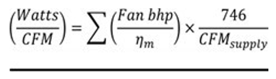
Where:
|
Fan bhp |
= |
Brake horsepower for each supply, exhaust and other fan in the system at design maximum airflow rate. |
|
ƞm |
= |
Fan motor efficiency including all motor, drive and other losses for each fan in the system. |
|
CFMsupply |
= |
Design maximum airflow rate of outdoor (supply) air. |
C403.3.5.3 Heating and cooling system fan controls. Heating and cooling equipment fans, heating and cooling circulation pumps, and terminal unit fans shall cycle off and terminal unit primary cooling air shall be shut off when there is no call for heating or cooling in the zone.
EXCEPTION: Fans used for heating and cooling using less than 0.12 watts per cfm may operate when space temperatures are within the setpoint deadband (Section C403.4.1.2) to provide destratification and air mixing in the space.
C403.3.5.4 Decoupled DOAS supply air. The DOAS supply air shall be delivered directly to the occupied space or downstream of the terminal heating and/or cooling coils.
EXCEPTIONS:
1. Active chilled beam systems.
2. Sensible only cooling terminal units with pressure independent variable airflow regulating devices limiting the DOAS supply air to the greater of latent load or minimum ventilation requirements.
3. Terminal heating and/or cooling units that comply with the low fan power allowance requirements in the exception of Section C403.3.5.3.
C403.3.5.5 Supplemental heating and cooling. Supply air stream heating in the DOAS system shall comply with Section C403.7.3. Cooling is permitted for dehumidification only. Cooling coil shall be sized to meet peak dehumidification requirement at design outdoor temperatures, and no larger. Cooling coil shall be controlled to maintain supply air relative humidity or zone relative humidity.
EXCEPTIONS:
1. Heating permitted for defrost control shall be locked out when outside air temperatures are above 35°F (2°C). Supplemental heating for defrost shall modulate to 10 percent of the peak capacity, and shall be sized to prevent frost damage to the unit at design temperatures and provide supply air less than or equal to 55°F (13°C).
2. A DOAS serving Group R-1 or R-2 occupancy spaces that are served by zonal heating systems, but not by zonal heat pumps, air conditioners, or other zonal mechanical cooling systems, is permitted to be provided with a supplemental heating and cooling system in compliance with Section C403.1.4.
C403.3.5.6 Impracticality. Where the code official determines that full compliance with one or more of the requirements in Sections C403.3.5.1 through C403.3.5.5 is impractical, it is permissible to provide an approved alternate means of compliance that achieves a comparable level of energy efficiency as the requirement(s) deemed impractical. For the purposes of this section, impractical means that an HVAC system complying with all requirements in Section C403.3.5 cannot effectively be utilized due to an unusual use or configuration of the building.
C403.3.6 (Reserved)
C403.3.7 Hydronic system flow rate. Chilled water and condenser water piping shall be designed such that the design flow rate in each pipe segment shall not exceed the values listed in Table C403.3.7 for the appropriate total annual hours of operation. Pipe sizes for systems that operate under variable flow conditions (e.g., modulating 2-way control valves at coils) and that contain variable speed pump motors are permitted to be selected from the “Variable Flow/Variable Speed” columns. All others shall be selected from the “Other” columns.
EXCEPTION: Design flow rates exceeding the values in Table C403.3.7 are permitted in specific sections of pipe if the pipe is not in the critical circuit at design conditions and is not predicted to be in the critical circuit during more than 30 percent of operating hours.
|
Pipe Size (in) |
≤ 2000 hours/year |
> 2000 and ≤ 4400 hours/year |
> 4400 hours/year |
|||
|---|---|---|---|---|---|---|
|
Other |
Variable Flow/ Variable Speed |
Other |
Variable Flow/ Variable Speed |
Other |
Variable Flow/ Variable Speed |
|
|
2-1/2 |
120 |
180 |
85 |
130 |
68 |
110 |
|
3 |
180 |
270 |
140 |
210 |
110 |
170 |
|
4 |
350 |
530 |
260 |
400 |
210 |
320 |
|
5 |
410 |
620 |
310 |
470 |
250 |
370 |
|
6 |
740 |
1100 |
570 |
860 |
440 |
680 |
|
8 |
1200 |
1800 |
900 |
1400 |
700 |
1100 |
|
10 |
1800 |
2700 |
1300 |
2000 |
1000 |
1600 |
|
12 |
2500 |
3800 |
1900 |
2900 |
1500 |
2300 |
|
Maximum velocity for pipes over 14 to 24 in. in size |
8.5 ft/s |
13.0 ft/s |
6.5 ft/s |
9.5 ft/s |
5.0 ft/s |
7.5 ft/s |
a There are no requirements for pipe sizes smaller than the minimum size or larger than the maximum size shown in the table.
C403.3.8 Hydronic coil selection. Hydronic coils shall comply with Sections C403.3.8.1 and C403.3.8.2.
EXCEPTION: Replacement coils within existing equipment.
C403.3.8.1 Chilled-water coil selection. Chilled-water cooling coils shall be selected to provide a 15°F or higher temperature difference between leaving and entering water temperatures and a minimum of 57°F leaving water temperature at design conditions.
EXCEPTIONS:
1. Chilled-water cooling coils that have an airside pressure drop exceeding 0.70 in. of water when rated at 500 fpm face velocity and dry conditions (no condensation).
2. Individual fan-cooling units with a design supply airflow rate ≤ 5000 cfm.
3. Constant-air-volume systems.
4. Coils selected at the maximum temperature difference allowed by the cooling plant equipment manufacturer’s approved operating conditions.
5. Passive coils (no mechanically supplied airflow).
6. Coils with design entering chilled-water temperature ≥ 50°F (10°C).
7. Coils with design entering air dry-bulb temperature ≤ 65°F (18°C).
C403.3.8.2 Hot-water coil selection. Hot-water heating coils shall be selected to provide a maximum 20°F temperature difference between leaving and entering water temperatures and a maximum of 118°F (48°C) entering water temperature at design conditions.
EXCEPTIONS:
1. Hot-water heating systems which utilize heat pumps as the primary source.
2. Individual terminal fan units with a design supply airflow rate ≤ 1500 cfm are exempt from the 20°F maximum temperature difference between leaving and entering water temperature requirement.
3. Passive coils (no mechanically supplied airflow).
4. Coils with design leaving air temperature ≥ 95°F (35°C).
C403.4 HVAC system controls. HVAC systems shall be provided with controls in accordance with Sections C403.4.1 through C403.4.12 and shall be capable of and configured to implement all required control functions in this code.
C403.4.1 Thermostatic controls. The supply of heating and cooling energy to each zone shall be controlled by individual thermostatic controls capable of responding to temperature within the zone. Controls in the same zone or in neighboring zones connected by openings larger than 10 percent of the floor area of either zone shall not allow for simultaneous heating and cooling. At a minimum, each floor of a building shall be considered as a separate zone. Controls on systems required to have economizers and serving single zones shall have multiple cooling stage capability and activate the economizer when appropriate as the first stage of cooling. See Section C403.5 for further economizer requirements. Where humidification or dehumidification or both is provided, at least one humidity control device shall be provided for each humidity control system.
EXCEPTIONS:
1. Independent perimeter systems that are designed to offset only building envelope heat losses or gains or both serving one or more perimeter zones also served by an interior system provided:
1.1. The perimeter system includes at least one thermostatic control zone for each building exposure having exterior walls facing only one orientation (within +/-45 degrees) (0.8 rad) for more than 50 contiguous feet (15,240 mm);
1.2. The perimeter system heating and cooling supply is controlled by a thermostat located within the zones served by the system; and
1.3. Controls are configured to prevent the perimeter system from operating in a different heating or cooling mode from the other equipment within the zones or from neighboring zones connected by openings larger than 10 percent of the floor area of either zone.
2. Where an interior zone and a perimeter zone are open to each other with permanent openings larger than 10 percent of the floor area of either zone, cooling in the interior zone is permitted to operate at times when the perimeter zone is in heating and the interior zone temperature is at least 5°F (2.8°C) higher than the perimeter zone temperature. For the purposes of this exception, a permanent opening is an opening without doors or other operable closures.
3. Dedicated outdoor air units that provide ventilation air, make-up air or replacement air for exhaust systems are permitted to be controlled based on supply air temperature. The supply air temperature shall be controlled to a maximum of 65°F (18.3°C) in heating and a minimum of 72°F (22°C) in cooling unless the supply air temperature is being reset based on the status of cooling or heating in the zones served or it being reset based on outdoor air temperature.
C403.4.1.1 Heat pump supplementary heat control. Heat pumps equipped with internal electric resistance heaters shall have controls that prevent supplemental heater operation when the heating load can be met by the heat pump alone during both steady-state operation and setback recovery. Supplemental heater operation is permitted during outdoor coil defrost cycles. Heat pumps equipped with supplementary heaters shall comply with all conditions of Section C403.1.4,
EXCEPTIONS:
1. Packaged terminal heat pumps (PTHPs) of less than 2 tons (24,000 Btu/hr) cooling capacity that have reverse-cycle demand defrost and are configured to operate in heat pump mode whenever the outdoor air temperatures are above 25°F (-3.9°C) and the unit is not in defrost.
2. Heat pumps whose minimum efficiency is regulated by NAECA and whose ratings meet the requirements shown in Table C403.3.2(2) and include all usage of internal electric resistance heating.
C403.4.1.2 Deadband. Where used to control both heating and cooling, zone thermostatic controls shall be configured to provide a temperature range or deadband of at least 5°F (2.8°C) within which the supply of heating and cooling energy to the zone is shut off or reduced to a minimum.
EXCEPTIONS:
1. Thermostats requiring manual changeover between heating and cooling modes.
2. Occupancies or applications requiring precision in indoor temperature control as approved by the code official.
C403.4.1.3 Setpoint overlap restriction. Where a zone has a separate heating and a separate cooling thermostatic control located within the zone, a limit switch, mechanical stop or direct digital control system with software programming shall be configured to prevent the heating setpoint from exceeding the cooling setpoint and to maintain a deadband in accordance with Section C403.4.1.2.
C403.4.1.4 Heated or cooled vestibules and air curtains. The heating system for heated vestibules and air curtains with integral heating shall be provided with controls configured to shut off the source of heating when the outdoor air temperature is greater than 45°F (7°C). Vestibule heating and cooling systems shall be controlled by a thermostat located in the vestibule configured to limit heating to a temperature not greater than 60°F (16°C) and cooling to a temperature not less than 85°F (29°C).
EXCEPTIONS:
1. Control of heating or cooling provided by transfer air that would otherwise be exhausted.
2. Vestibule heating only systems are permitted to be controlled without an outdoor air temperature lockout when controlled by a thermostat located in the vestibule configured to limit heating to a temperature not greater than 45°F (7°C) where required for freeze protection of piping and sprinkler heads located in the vestibule.
C403.4.1.5 Hot water boiler outdoor temperature setback control. Hot water boilers that supply heat to the building through one- or two-pipe heating systems shall have an outdoor setback control that lowers the boiler water temperature based on the outdoor temperature.
C403.4.1.6 Operable opening switches for HVAC system thermostatic control. Operable openings meeting the minimum size criteria of Section C402.5.11 and that open to the outdoors from a conditioned space must have controls configured to do the following once doors have been open for 5 minutes:
1. Disable the mechanical heating to the zone or reset the space heating temperature setpoint to 55°F or less within 5 minutes of the door open enable signal.
2. Disable the mechanical cooling to the zone or reset the space cooling temperature setpoint to 85°F or more within 5 minutes of the door open enable signal.
EXCEPTION: Hydronic radiant heating and cooling systems.
C403.4.1.7 Demand responsive controls. Thermostatic controls for heating or cooling systems shall be provided with demand responsive controls capable of increasing the cooling setpoint and decreasing the heating setpoint by no less than 4°F (2.2°C). The thermostatic controls shall be capable of performing all other functions provided by the control when the demand responsive controls are not available. Systems with direct digital control of individual zones report to a central control panel shall be capable of remotely increasing the cooling setpoint and decreasing the heating setpoint for each zone by no less than 4°F (2.2°C).
EXCEPTIONS:
1. Health care and assisted living facilities.
2. Group R-2 occupancy dwelling and sleeping units.
C403.4.2 Off-hour controls. For all occupancies other than Group R, and for conditioned spaces other than dwelling units and sleeping units within Group R occupancies, each zone shall be provided with thermostatic setback controls that are controlled by either an automatic time clock or programmable control system.
EXCEPTIONS:
1. Zones that will be operated continuously.
2. Zones with a full HVAC load demand not exceeding 6,800 Btu/h (2 kW) and having a manual shutoff switch located with ready access.
C403.4.2.1 Thermostatic setback. Thermostatic setback controls shall be configured to set back or temporarily operate the system to maintain zone temperatures down to 55°F (13°C) or up to 85°F (29°C).
C403.4.2.2 Automatic setback and shutdown. Automatic time clock or programmable controls shall be capable of starting and stopping the system for seven different daily schedules per week and retaining their programming and time setting during a loss of power for at least 10 hours. Additionally, the controls shall have a manual override that allows temporary operation of the system for up to 2 hours; a manually operated timer configured to operate the system for up to 2 hours; or an occupancy sensor.
C403.4.2.3 Automatic start and stop. Automatic start and stop controls shall be provided for each HVAC system. The automatic start controls shall be configured to automatically adjust the daily start time of the HVAC system in order to bring each space to the desired occupied temperature immediately prior to scheduled occupancy. Automatic stop controls shall be provided for each HVAC system with direct digital control of individual zones. The automatic stop controls shall be configured to reduce the HVAC system’s heating temperature setpoint and increase the cooling temperature setpoint by at least 2°F (1.1°C) before scheduled unoccupied periods based upon the thermal lag and acceptable drift in space temperature that is within comfort limits.
C403.4.2.4 Exhaust system off-hour controls. For all occupancies other than Group R, exhaust systems serving spaces within the conditioned envelope shall be controlled by either an automatic time clock, thermostatic controls or programmable control system to operate on the same schedule as the HVAC systems providing their make-up air.
EXCEPTIONS:
1. Exhaust systems requiring continuous operation.
2. Exhaust systems that are controlled by occupancy sensor control configured with automatic on and automatic shutoff within 15 minutes after occupants have left the space.
C403.4.2.5 Transfer and destratification fan system off-hour controls. For all occupancies other than Group R, transfer fan or mixing fan systems serving spaces within the conditioned envelope shall be controlled by either an automatic time clock, thermostatic controls or programmable control system to operate on the same schedule as the associated HVAC systems.
EXCEPTION: Transfer fan and destratification fan systems that are controlled by occupancy sensor control configured with manual on and automatic shutoff within 15 minutes after occupants have left the space.
C403.4.3 Hydronic systems controls. The heating of fluids that have been previously mechanically cooled and the cooling of fluids that have been previously mechanically heated shall be limited in accordance with Sections C403.4.3.1 through C403.4.3.3. Hydronic heating systems comprised of multiple-packaged boilers and designed to deliver conditioned water or steam into a common distribution system shall include automatic controls configured to sequence operation of the boilers. Hydronic heating systems comprised of a single boiler and greater than 500,000 Btu/h (146,550 W) input design capacity shall include either a multi-staged or modulating burner.
403.4.3.1 Three-pipe system. Hydronic systems that use a common return system for both hot water and chilled water are prohibited.
C403.4.3.2 Two-pipe changeover system. Systems that use a common distribution system to supply both heated and chilled water shall be designed to allow a dead band between changeover from one mode to the other of at least 15°F (8.3°C) outside air temperatures; be designed to and provided with controls that will allow operation in one mode for at least 4 hours before changing over to the other mode; and be provided with controls that allow heating and cooling supply temperatures at the changeover point to be no more than 30°F (16.7°C) apart.
C403.4.3.3 Hydronic (water loop) heat pump systems. Hydronic heat pump systems shall comply with Sections C403.4.3.3.1 through C403.4.3.3.3.
C403.4.3.3.1 Temperature dead band. Hydronic heat pumps connected to a common heat pump water loop with central devices for heat rejection and heat addition shall have controls that are configured to provide a heat pump water supply temperature dead band of at least 20°F (11.1°C) between initiation of heat rejection and heat addition by the central devices.
EXCEPTION: Where a system loop temperature optimization controller is installed and can determine the most efficient operating temperature based on real time conditions of demand and capacity, dead bands of less than 20°F (11°C) shall be permitted.
C403.4.3.3.2 Heat rejection. The following shall apply to hydronic water loop heat pump systems:
1. Where a closed-circuit cooling tower is used directly in the heat pump loop, either an automatic valve shall be installed to bypass the flow of water around the closed-circuit cooling tower, except for the minimum flow necessary for freeze protection. Flow controls for freeze protection shall not allow water through the closed-circuit cooling tower when outdoor temperatures are above the freezing point of the glycol/water solution, i.e. 32°F (0°C) for 100 percent water applications, and 18°F (-7.8°C) for 20 percent by mass propylene glycol solution.
2. Where an open-circuit cooling tower is used directly in the heat pump loop, an automatic valve shall be installed to bypass all heat pump water flow around the open-circuit cooling tower.
3. Where an open-circuit cooling tower is used in conjunction with a separate heat exchanger to isolate the open-circuit cooling tower from the heat pump loop, heat loss shall be controlled by shutting down the circulation pump on the cooling tower loop.
EXCEPTION: Where it can be demonstrated that a heat pump system will be required to reject heat throughout the year.
C403.4.3.3.3 Isolation valve. Each hydronic heat pump on the hydronic system having a total pump system power exceeding 10 horsepower (hp) (7.5 kW) shall have a two-way (but not three-way) valve. For the purposes of this section, pump system power is the sum of the nominal power demand (i.e., nameplate horsepower at nominal motor efficiency) of motors of all pumps that are required to operate at design conditions to supply fluid from the heating or cooling source to all heat transfer devices (e.g., coils, heat exchanger) and return it to the source. This converts the system into a variable flow system and, as such, the primary circulation pumps shall comply with the variable flow requirements in Section C403.4.6.
C403.4.4 Part load controls. Hydronic systems greater than or equal to 300,000 Btu/h (88 kW) in design output capacity supplying heated or chilled water to comfort conditioning systems shall include controls that are configured to:
1. Automatically reset the supply-water temperatures in response to varying building heating and cooling demand using coil valve position, zone-return water temperature or outdoor air temperature. The temperature shall be reset by not less than 25 percent of the design supply-to-return water temperature difference.
EXCEPTIONS:
1. Hydronic systems serving hydronic heat pumps.
2. Hydronic systems with thermal energy storage where resetting the supply-water temperature would reduce the capacity of the storage.
2. Automatically vary fluid flow for hydronic systems with a combined pump motor capacity of 2 hp or larger with three or more control valves or other devices by reducing the system design flow rate by not less than 50 percent or the maximum reduction allowed by the equipment manufacturer for proper operation of equipment by valves that modulate or step open and close, or pumps that modulate or turn on and off as a function of load.
3. Automatically vary pump flow on heating water systems, chilled-water systems and heat rejection loops serving water-cooled unitary air conditioners as follows:
3.1. Where pumps operate continuously or operate based on a time schedule, pumps with nominal output motor power of 2 hp or more shall have a variable speed drive.
3.2. Where pumps have automatic direct digital control configured to operate pumps only when zone heating or cooling is required, a variable speed drive shall be provided for pumps with motors having the same or greater nominal output power indicated in Table C403.4.4 based on the climate zone and system served.
4. Where variable speed drive is required by Item 3 of this section, pump motor power input shall be not more than 30 percent of design wattage at 50 percent of the design water flow. Pump flow shall be controlled to maintain one control valve nearly wide open or to satisfy the minimum differential pressure.
EXCEPTIONS:
1. Supply-water temperature reset is not required for chilled-water systems supplied by off-site district chilled water or chilled water from ice storage systems.
2. Variable pump flow is not required on dedicated coil circulation pumps where needed for freeze protection.
3. Variable pump flow is not required on dedicated equipment circulation pumps where configured in primary/secondary design to provide the minimum flow requirements of the equipment manufacturer for proper operation of equipment.
4. Variable speed drives are not required on heating water pumps where more than 50 percent of annual heat is generated by an electric boiler.
|
Climate Zones 4c, 5b |
VSD Required for Motors with Rated Output of at Least |
|---|---|
|
Heating water pumps |
≥ 5.0 hp |
|
Chilled water and heat rejection loop pumps |
≥ 5.0 hp |
C403.4.5 Pump isolation. Chilled water plants including more than one chiller shall be capable of and configured to reduce flow automatically through the chiller plant when a chiller is shut down and automatically shut off flow to chillers that are shut down. Chillers piped in series for the purpose of increased temperature differential shall be considered as one chiller.
Boiler systems including more than one boiler shall be capable of and configured to reduce flow automatically through the boiler system when a boiler is shut down.
C403.4.6 Variable flow controls. Individual pumps required by this code to have variable speed control shall be controlled in one of the following manners:
1. For systems having a combined pump motor horsepower less than or equal to 20 hp (15 kW) and without direct digital control of individual coils, pump speed shall be a function of either:
1.1. Required differential pressure; or
1.2. Reset directly based on zone hydronic demand, or other zone load indicators; or
1.3. Reset directly based on pump power and pump differential pressure; or
1.4. Reset directly by an integral controller based on the relationship between variable speed controller frequency and power.
2. For systems having a combined pump motor horsepower that exceeds 20 hp (15 kW) or smaller systems with direct digital control, pump speed shall be a function of either:
2.1. The static pressure set point as reset based on the valve requiring the most pressure; or
2.2. Directly controlled based on zone hydronic demand; or
2.3. Reset directly by an integral controller based on the relationship between variable speed controller frequency and power.
C403.4.7 Combustion heating equipment controls. Combustion heating equipment with a capacity over 225,000 Btu/h shall have modulating or staged combustion control.
EXCEPTIONS:
1. Boilers.
2. Radiant heaters.
C403.4.7.1 Combustion decorative vented appliance, combustion 2 and fire pit controls. Combustion decorative vented appliances, combustion fireplaces and fire pits shall be equipped with local controls to limit operation to a maximum duration of one hour without override hold capability or shall be controlled by occupancy sensor control configured with manual on and automatic shutoff within 15 minutes after occupants have left the space.
C403.4.8 Group R-1 hotel/motel guestrooms. See Section C403.7.4.
C403.4.9 Group R-2 and R-3 dwelling units. The primary space conditioning system within each dwelling unit shall be provided with at least one programmable thermostat for the regulation of space temperature. The thermostat shall allow for, at a minimum, a 5-2 programmable schedule (weekdays/weekends) and be capable of providing at least two programmable setback periods per day.
Each additional system provided within the dwelling unit shall be provided with at least one adjustable thermostat for the regulation of temperature.
EXCEPTIONS:
1. Systems controlled by an occupant sensor that is configured to shut the system off when no occupant is sensed for a period of up to 30 minutes.
2. Systems controlled solely by a manually operated timer configured to operate the system for no more than two hours.
3. Ductless heat pumps.
Each thermostat shall be capable of being set by adjustment or selection of sensors and configured as follows:
1. When used to control heating only: 55°F to 75°F.
2. When used to control cooling only: 70°F to 85°F.
3. All other: 55°F to 85°F with an adjustable dead band configured to at least 5°F in accordance with Section C403.4.1.2.
C403.4.10 Group R-2 sleeping units. The primary space conditioning system within each sleeping unit shall be provided with at least one programmable thermostat for the regulation of space temperature. The thermostat shall allow for, at a minimum, a 5-2 programmable schedule (weekdays/weekends) and be capable of providing at least two programmable setback periods per day.
Each additional system provided within the sleeping unit shall be provided with at least one adjustable thermostat for the regulation of temperature.
EXCEPTIONS:
1. Systems controlled by an occupant sensor that is configured to shut the system off when no occupant is sensed for a period of up to 30 minutes.
2. Systems controlled solely by a manually operated timer configured to operate the system for no more than two hours.
3. Zones with a full HVAC load demand not exceeding 3,400 Btu/h (1 kW) and having a manual shutoff switch located with ready access.
4. Ductless heat pumps.
Each thermostat shall be capable of being set by adjustment or selection of sensors and configured as follows:
1. When used to control heating only: 55°F to 75°F;
2. When used to control cooling only: 70°F to 85°F;
3. All other: 55°F to 85°F with an adjustable dead band configured to at least 5°F in accordance with Section C403.4.1.2.
C403.4.11 Direct digital control systems. Direct digital control (DDC) shall be required as specified in Sections C403.4.11.1 through C403.4.11.4.
C403.4.11.1 DDC applications. DDC shall be provided in the applications and qualifications listed in Table C403.4.11.1 and for load management measures where installed to meet the requirements of Section C406.3.
C403.4.11.2 DDC controls. Where DDC is required by Section C403.4.11.1, the DDC system shall be configured to perform all of the following functions, as required to provide the system and zone control logic required in Sections C403.2, C403.5, C403.6.8 and C403.4.3:
1. Monitor zone and system demand for fan pressure, pump pressure, heating and cooling.
2. Transfer zone and system demand information from zones to air distribution system controllers and from air distribution systems to heating and cooling plant controllers.
C403.4.11.3 DDC display. Where DDC is required by Section C403.4.11.1 for new buildings, the DDC system shall be configured to gather and provide trending data and graphically displaying input and output points.
C403.4.11.4 DDC demand response setpoint adjustment. Where DDC is required by Section C403.4.11.1 for new buildings and serve mechanical systems with a cooling capacity exceeding 780,000 Btu/h (2,662 kW), the DDC system shall be capable of demand response setpoint adjustment. The DDC system shall be configured with control logic to increase the cooling zone setpoints by at least 2°F (1°C) and reduce the heating zone setpoints by at least 2°F (1°C) when activated by a demand response signal. The demand response signal shall be a binary input to the control system or other interface approved by the serving electric utility.
|
Building Status |
Application |
Qualifications |
|---|---|---|
|
New building |
Air-handling system and all zones served by the system |
Individual systems supplying more than three zones and with fan system bhp of 10 hp and larger |
|
Chilled-water plant and all coils and terminal units served by the system |
Individual plants supplying more than three zones and with design cooling capacity of 300,000 Btu/h and larger |
|
|
Hot-water plant and all coils and terminal units served by the system |
Individual plants supplying more than three zones and with design heating capacity of 300,000 Btu/h and larger |
|
|
Alteration or addition |
Zone terminal unit such as VAV box |
Where existing zones served by the same air-handling, chilled-water, or hot-water system have DDC |
|
Air-handling system or fan coil |
Where existing air-handling system(s) and fan coil(s) served by the same chilled- or hot-water plant have DDC |
|
|
New air-handling system and all new zones served by the system |
Individual systems with fan system bhp of 10 hp and larger and supplying more than three zones and more than 75 percent of zones are new |
|
|
New or upgraded chilled-water plant |
Where all chillers are new and plant design cooling capacity is 300,000 Btu/h and larger |
|
|
New or upgraded hot-water plant |
Where all boilers are new and plant design heating capacity is 300,000 Btu/h and larger |
C403.4.12 Pressure independent control valves. Where design flow rate of heating water and chiller water coils is 5 gpm or higher, modulating pressure independent control valves shall be provided.
C403.5 Economizers. Air economizers shall be provided on all new cooling systems including those serving computer server rooms, electronic equipment, radio equipment, and telephone switchgear. Economizers shall comply with Sections C403.5.1 through C403.5.5.
EXCEPTIONS:
1a. For other than Group R-2 occupancies, cooling system where the supply fan is not installed outside the building thermal envelope nor in a mechanical room adjacent to outdoors, and is installed in conjunction with DOAS complying with Section C403.3.5 and serving only spaces with year-round cooling loads from lights and equipment of less than 5 watts per square foot.
1b. For Group R-2 occupancies, cooling system where the supply fan is not installed outside the building thermal envelope nor in a mechanical room adjacent to outdoors, and is installed in conjunction with DOAS complying with Section C403.3.5, where the ERV/HRV has a minimum 67 percent sensible recovery or 60 percent enthalpy recovery heating effectiveness, and serving only spaces with year-round cooling loads from lights and equipment of less than 5 watts per square foot.
2. Unitary or packaged systems serving one zone with dehumidification where an air economizer would increase the overall building energy consumption. New humidification equipment shall comply with Section C403.3.2.7.
3. Unitary or packaged systems serving one zone where the cooling efficiency meets or exceeds the efficiency requirements in Table C403.5(3).
4. Equipment serving chilled beams and chilled ceiling space cooling systems only which are provided with a water economizer meeting the requirements of Section C403.5.4.
5. For Group R occupancies, cooling unit where the supply fan is not installed outside the building thermal envelope or in a mechanical room adjacent to outdoors with a total cooling capacity less than 20,000 Btu/h and other cooling units with a total cooling capacity less than 54,000 Btu/h provided that these are high-efficiency cooling equipment with IEER, CEER, SEER, and EER values more than 15 percent higher than minimum efficiencies listed in Tables C403.3.2(1), C403.3.2(2), C403.3.2(4), C403.3.2(8) and C403.3.2(9) or an IPLV kW/ton that is at least 15 percent lower than the minimum efficiencies listed in Table C403.3.2(3) or C403.3.2(15), in the appropriate size category, using the same test procedures. Equipment shall be listed in the appropriate certification program to qualify for this exception. For split systems, compliance is based on the cooling capacity of individual fan coil units.
6. Equipment used to cool Controlled Plant Growth Environments provided these are high-efficiency cooling equipment with SEER, EER and IEER values a minimum of 20 percent greater than the values listed in Tables C403.3.2 (1), (3), (4), and (15).
7. Equipment serving a space with year-round cooling loads from lights and equipment of 5 watts per square foot or greater complying with the following criteria:
7.1. Equipment serving the space utilizes chilled water as the cooling source; and
7.2. The chilled water plant includes a condenser heat recovery system that meets the requirements of Section C403.9.2.1 or the building and water-cooled system meets the following requirements:
7.2.1. A minimum of 90 percent (capacity-weighted) of the building space heat is provided by hydronic heating water.
7.2.2. Chilled water plant includes a heat recovery chiller or water-to-water heat pump capable of rejecting heat from the chilled water system to the hydronic heating equipment capacity.
7.2.3. Heat recovery chillers shall have a minimum COP of 7.0 when providing heating and cooling water simultaneously.
8. Water-cooled equipment served by systems meeting the requirements of Section C403.9.2.4 Condenser heat recovery.
9. Dedicated outdoor air systems that include energy recovery as required by Section C403.7.6 but that do not include mechanical cooling.
10. Dedicated outdoor air systems not required by Section C403.7.6 to include energy recovery that modulate the supply airflow to provide only the minimum outdoor air required by Section C403.2.2.1 for ventilation, exhaust air make-up, or other process air delivery.
11. Equipment used to cool any dedicated server room, electronic equipment room, elevator machine room or telecom switch room provided the system complies with Option a, b, c, d or e in Table C403.5(9) below. The total cooling capacity of all fan systems qualifying under this exception without economizers shall not exceed 240,000 Btu/h per building or 10 percent of its air economizer capacity, whichever is greater. This exception shall not be used for Total Building Performance or Target Performance Path compliance.
11. Medical and laboratory equipment that is directly water-cooled and is not dependent upon space air temperature.
|
|
Equipment Type |
Higher Equipment Efficiency |
Part-Load Control |
Economizer |
|---|---|---|---|---|
|
Option a |
Tables C403.3.2(1), C403.3.2(2) and C403.3.2(14)a |
+15%b |
Required over 85,000 Btu/hc |
None Required |
|
Option b |
Tables C403.3.2(1), C403.3.2(2) and C403.3.2(14)a |
+5%d |
Required over 85,000 Btu/hc |
Waterside Economizere |
|
Option c |
ASHRAE Standard 127f |
+0%g |
Required over 85,000 Btu/hc |
Waterside Economizere |
|
Option d |
Table C403.3.2(7)h |
+ 25%i |
Required for all chillersj |
None Required |
|
Option e |
Table C403.3.2(7)h |
+ 10/15%k |
Required over 85,000 Btu/hc |
Dedicated waterside Economizere |
Footnotes for Table C403.5(9):
a For a system where all of the cooling equipment is subject to the AHRI standards listed in Tables C403.3.2(1), C403.3.2(2), and C403.3.2 (14), the system shall comply with the higher equipment efficiency, part-load control and economizer requirements of the row in which this footnote is located, including the associated footnotes (note that if the system contains any cooling equipment that exceeds the capacity limits in Table C403.3.2(1), C403.3.2(2), or C403.3.2 (14), or if the system contains any cooling equipment that is not included in Table C403.3.2(1), C403.3.2(2), or C403.3.2 (14), then the system is not allowed to use this option).
b The cooling equipment shall have a SEER/EER value and an IEER/IPLV value that each is a minimum of 15 percent greater than the value listed in Tables C403.3.2(1), C403.3.2(2), and C403.3.2 (14).
c For units with a total cooling capacity over 85,000 Btu/h, the system shall utilize part-load capacity control schemes that are able to modulate to a part-load capacity of 50 percent of the load or less that results in the compressor operating at the same or higher EER at part loads than at full load (e.g., minimum of two-stages of compressor unloading such as cylinder unloading, two-stage scrolls, dual tandem scrolls, but hot gas bypass is not credited as a compressor unloading system).
d The cooling equipment shall have a SEER/EER value and an IEER/IPLV value that each is a minimum of 5 percent greater than the value listed in Tables C403.3.2(1), C403.3.2(2), and C403.3.2 (14).
e The system shall include a water economizer in lieu of air economizer. Water economizers shall meet the requirements of C403.5.1 and C403.5.2 and be capable of providing the total concurrent cooling load served by the connected terminal equipment lacking airside economizer, at outside air temperatures of 50°F dry-bulb/45°F wet-bulb and below. For this calculation, all factors including solar and internal load shall be the same as those used for peak load calculations, except for the outside temperatures. The equipment shall be served by a dedicated condenser water system unless a nondedicated condenser water system exists that can provide appropriate water temperatures during hours when waterside economizer cooling is available.
f For a system where all cooling equipment is subject to ASHRAE Standard 127, the system shall comply with the higher equipment efficiency, part-load control, and economizer requirements of the row in which this footnote is located, including the associated footnotes.
g The cooling equipment subject to the ASHRAE Standard 127 shall have a SCOP value that is a minimum of 10 percent greater than the value listed in Tables C403.3.2(1), C403.3.2(2), and C403.3.2 (14) (1.10 × values in these tables) when determined in accordance with the rating conditions ASHRAE Standard 127 (i.e., not the rating conditions in AHRI Standard 210/240 or 340/360). This information shall be provided by an independent third party.
h For a system with chillers subject to the AHRI standards listed in Table C403.3.2(7) (as an example, a chilled water system with fan coil units), the system shall comply with the higher equipment efficiency, part-load control and economizer requirements of the row in which this footnote is located, including the associated footnotes.
i The cooling equipment shall have an full-load EER value and an IPLV value that is a minimum of 25 percent greater than the value listed in Table C403.3.2(7) (1.25 × value in Table C403.3.2(7) or a full-load and IPLV kW/ton that is at least 25 percent lower than the value listed in Table C403.3.2(7) (0.75 × value in Table C403.3.2(7)).
j For all chillers, the system shall utilize part-load capacity control schemes that are able to modulate to a part-load capacity of 50 percent of the load or less and that result in the compressor operating at the same or higher EER at part loads than at full load (e.g., minimum of two-stages of compressor unloading such as cylinder unloading, two-stage scrolls, or dual tandem scrolls, but hot gas bypass is not a qualifying compressor unloading system).
k For air-cooled chillers, the cooling equipment shall have an IPLV EER value that is a minimum of 10 percent greater than the IPLV EER value listed in Table C403.3.2(7) (1.10 × values in Table C403.3.2(7). For water-cooled chillers, the cooling equipment shall have an IPLV kW/ton that is at least 15 percent lower than the IPLV kW/ton value listed in Table C403.3.2(7) (0.85 × values in Table C403.3.2(7)).
|
Climate Zones |
Efficiency Improvementa |
|---|---|
|
4C |
64% |
|
5B |
59% |
a If a unit is rated with an IPLV, IEER or SEER then to eliminate the required air or water economizer, the minimum cooling efficiency of the HVAC unit must be increased by the percentage shown. If the HVAC unit is only rated with a full load metric like EER or COP cooling, then these must be increased by the percentage shown.
C403.5.1 Integrated economizer control. Economizer systems shall be integrated with the mechanical cooling system and be configured to provide partial cooling even where additional mechanical cooling is required to provide the remainder of the cooling load. Controls shall not be capable of creating a false load in the mechanical cooling system by limiting or disabling the economizer or any other means, such as hot gas bypass, except at the lowest stage of mechanical cooling.
Units that include an air economizer shall comply with the following:
1. Unit controls shall have the mechanical cooling capacity control interlocked with the air economizer controls such that the outdoor air damper is at the 100 percent open position when mechanical cooling is on and the outdoor air damper does not begin to close to prevent coil freezing due to minimum compressor run time until the leaving air temperature is less than 45°F (7°C).
2. Direct expansion (DX) units with cooling capacity 65,000 Btu/H (19 kW) or greater of rated capacity shall comply with the following:
2.1. DX units that control the capacity of the mechanical cooling directly based on occupied space temperature shall have not fewer than two stages of mechanical cooling capacity.
2.2. Other DX units, including those that control space temperature by modulating the airflow to the space, shall be in accordance with Table C403.5.1.
|
Rating Capacity |
Minimum Number of Mechanical Cooling Stages |
Minimum Compressor Displacementa |
|---|---|---|
|
≥ 65,000 Btu/h and < 240,000 Btu/h |
3 stages |
≤ 35% of full load |
|
≥ 240,000 Btu/h |
4 stages |
≤ 25% of full load |
For SI: 1 Btu/h = 0.2931 W
a. For mechanical cooling stage control that does not use variable compressor displacement, the percent displacement shall be equivalent to the mechanical cooling capacity reduction evaluated at the full load rating conditions for the compressor.
C403.5.2 Economizer heating system impact. HVAC system design and economizer controls shall be such that economizer operation does not increase building heating energy use during normal operation.
EXCEPTION: Economizers on VAV systems that cause zone level heating to increase due to a reduction in supply air temperature.
C403.5.3. Air economizers. Air economizers shall comply with Sections C403.5.3.1 through C403.5.3.5.
C403.5.3.1 Design capacity. Air economizer systems shall be configured to modulate outdoor air and return air dampers to provide up to 100 percent of the design supply air quantity as outdoor air for cooling.
C403.5.3.2 Control signal. Economizer controls and dampers shall be configured to sequence the dampers with mechanical cooling equipment and shall not be controlled by only mixed air temperature. Air economizers on systems with cooling capacity greater than 65,000 Btu/h shall be configured to provide partial cooling even when additional mechanical cooling is required to meet the remainder of the cooling load.
EXCEPTION: The use of mixed air temperature limit control shall be permitted for systems that are both controlled from space temperature (such as single zone systems) and having cooling capacity less than 65,000 Btu/h.
C403.5.3.3 High-limit shutoff. Air economizers shall be configured to automatically reduce outdoor air intake to the design minimum outdoor air quantity when outdoor air intake will no longer reduce cooling energy usage. High-limit shutoff control types shall be chosen from Table C403.5.3.3. High-limit shutoff control settings for these control types shall be those specified in Table C403.5.3.3.
|
DEVICE TYPE |
REQUIRED HIGH LIMIT (Economizer Off When): |
REQUIRED HIGH LIMIT FOR CYCLING FANSc (Economizer Off When): |
||
|---|---|---|---|---|
|
EQUATION |
DESCRIPTION |
EQUATION |
DESCRIPTION |
|
|
Fixed dry bulb |
TOA > 75°F |
Outdoor air temperature exceeds 75°F |
TOA > 70°F |
Outdoor air temperature exceeds 70°F |
|
Differential dry bulb |
TOA > TRA |
Outdoor air temperature exceeds return air temperature |
TOA > (TRA - 5) |
Outdoor air temperature exceeds return air temperature - 5°F |
|
Fixed enthalpy with fixed dry-bulb temperatures |
hOA > 28 Btu/lba or TOA > 75°F |
Outdoor air enthalpy exceeds 28 Btu/lb of dry aira or outdoor temperature exceeds 75°F |
hOA > 26 Btu/lba or TOA > 70°F |
Outdoor air enthalpy exceeds 26 Btu/lb of dry aird or outdoor temperature exceeds 70°F |
|
Differential enthalpy with fixed dry-bulb temperatures |
hOA > hRA or TOA > 75°F |
Outdoor air enthalpy exceeds return air enthalpy or outdoor temperature exceeds 75°F |
hOA > (hRA – 2) or TOA > 70°F |
Outdoor air enthalpy exceeds return air enthalpy or outdoor temperature exceeds 70°F |
For SI: °C = (°F - 32) × 5/9, 1 Btu/lb = 2.33 kJ/kg.
a. At altitudes substantially different than sea level, the Fixed Enthalpy limit shall be set to the enthalpy value at 75°F and 50-percent relative humidity. As an example, at approximately 6,000 feet elevation the fixed enthalpy limit is approximately 30.7 Btu/lb.
b. Devices with selectable set point shall be capable of being set to within 2°F and 2 Btu/lb of the set point listed.
c. Where fans cycle on only to provide heating and cooling, limits are adjusted lower to compensate for fan energy use in economizer mode.
d. For cycling fans, at altitudes substantially different than sea level, the fixed enthalpy limit shall be set to the enthalpy value at 70°F and 50% relative humidity.
C403.5.3.4 Relief of excess outdoor air. Systems shall be capable of relieving excess outdoor air during air economizer operation to prevent over-pressurizing the building. The relief air outlet shall be located to avoid recirculation into the building.
C403.5.3.5 Economizer dampers. Return, exhaust/relief and outdoor air dampers used in economizers shall comply with Section C403.7.8.
C403.5.4 Water-side economizers. Water-side economizers shall comply with Sections C403.5.4.1 and C403.5.4.2.
C403.5.4.1 Design capacity. Water economizer systems shall be configured to cool supply air by indirect evaporation and providing up to 100 percent of the expected system cooling load at outdoor air temperatures of not greater than 50°F dry-bulb (10°C dry-bulb)/45°F wet-bulb (7.2°C wet-bulb).
EXCEPTION: Systems where dehumidification requirements cannot be met using outdoor air temperatures of 50°F dry-bulb (10°C dry-bulb)/45°F wet-bulb (7.2°C wet-bulb) and where 100 percent of the expected system cooling load at 45°F dry-bulb (7.2°C dry-bulb)/40°F wet-bulb (4.5°C wet-bulb) is met with evaporative water economizers.
C403.5.4.2 Maximum pressure drop. Precooling coils and water-to-water heat exchangers used as part of a water economizer system shall either have a water-side pressure drop of less than 15 feet (4572 mm) of water or a secondary loop shall be created so that the coil or heat exchanger pressure drop is not seen by the circulating pumps when the system is in the normal cooling (noneconomizer) mode.
C403.5.5 Economizer fault detection and diagnostics (FDD). Air-cooled unitary direct-expansion units with a cooling capacity of 54,000 Btu/h or greater listed in the tables in Section C403.3.2 that are equipped with an economizer in accordance with Section C403.5 shall include a fault detection and diagnostics (FDD) system complying with the following:
1. The following temperature sensors shall be permanently installed to monitor system operation:
1.1. Outside air.
1.2. Supply air.
1.3. Return air.
2. Temperature sensors shall have an accuracy of ±2°F (1.1°C) over the range of 40°F to 80°F (4°C to 26.7°C).
3. Refrigerant pressure sensors, where used, shall have an accuracy of ±3 percent of full scale.
4. The unit controller shall be configured to provide system status by indicating the following:
4.1. Free cooling available.
4.2. Economizer enabled.
4.3. Compressor enabled.
4.4. Heating enabled.
4.5. Mixed air low limit cycle active.
4.6. The current value of each sensor.
5. The unit controller shall be capable of manually initiating each operating mode so that the operation of compressors, economizers, fans and the heating system can be independently tested and verified.
6. The unit shall be configured to report faults to a fault management application available for access by day-to-day operating or service personnel or annunciated locally on zone thermostats.
7. The FDD system shall be configured to detect the following faults:
7.1. Air temperature sensor failure/fault.
7.2. Not economizing when the unit should be economizing.
7.3. Economizing when the unit should not be economizing.
7.4. Damper not modulating.
7.5. Excess outdoor air.
C403.6 Requirements for mechanical systems serving multiple zones. Sections C403.6.1 through C403.6.10 shall apply to mechanical systems serving multiple zones.
C403.6.1 Variable air volume (VAV) and multiple zone systems. Supply air systems serving multiple zones shall be VAV systems that have zone controls configured to reduce the volume of air that is reheated, recooled or mixed in each zone to one of the following:
1. Twenty percent of the zone design peak supply for systems with direct digital control (DDC) and 30 percent of the maximum supply air for other systems.
2. Systems with DDC where items 2.1 through 2.3 apply.
2.1. The airflow rate in the deadband between heating and cooling does not exceed 20 percent of the zone design peak supply rate or higher allowed rates under Items 3, 4, or 5 of this section.
2.2. The first stage of heating modulates the zone supply air temperature setpoint up to a maximum setpoint while the airflow is maintained at the deadband flow rate.
2.3. The second stage of heating modulates the airflow rate from the deadband flow rate up to the heating maximum flow rate that is less than 50 percent of the zone design peak supply rate.
3. The outdoor airflow rate required to meet the minimum ventilation requirements of Chapter 4 of the International Mechanical Code.
4. Any higher rate that can be demonstrated to reduce overall system annual energy use by offsetting reheat/recool energy losses through a reduction in outdoor air intake for the system, as approved by the code official.
5. The airflow rates to comply with applicable codes or accreditation standards such as pressure relationships or minimum air change rates.
EXCEPTION: The following individual zones or entire air distribution systems are exempted from the requirement for VAV control:
1. Zones or supply air systems where not less than 75 percent of the energy for reheating or for providing warm air in mixing systems is provided from a site-recovered source, including condenser heat.
2. Systems that prevent reheating, recooling, mixing or simultaneous supply of air that has been previously cooled, either mechanically or through the use of economizer systems, and air that has been previously mechanically heated.
3. Ventilation systems complying with Section C403.3.5, DOAS, with ventilation rates comply with Section C403.2.2.
C403.6.2 Single duct variable air volume (VAV) systems, terminal devices. Single duct VAV systems shall use terminal devices capable of and configured to reduce the supply of primary supply air before reheating or recooling takes place.
C403.6.3 Dual duct and mixing VAV systems, terminal devices. Systems that have one warm air duct and one cool air duct shall use terminal devices which are capable of and configured to reduce the flow from one duct to a minimum before mixing of air from the other duct takes place.
C403.6.4 Supply-air temperature reset controls. Multiple zone HVAC systems shall include controls that are capable of and configured to automatically reset the supply-air temperature in response to representative building loads, or to outdoor air temperature. The controls shall be configured to reset the supply air temperature at least 25 percent of the difference between the design supply-air temperature and the design room air temperature. Controls that adjust the reset based on zone humidity are allowed. HVAC zones that are expected to experience relatively constant loads shall have maximum airflow designed to accommodate the fully reset supply air temperature.
EXCEPTIONS:
1. Systems that prevent reheating, recooling or mixing of heated and cooled supply air.
2. Seventy-five percent of the energy for reheating is from a site-recovered source.
C403.6.5 Multiple-zone VAV system ventilation optimization control. Multiple-zone VAV systems with direct digital control of individual zone boxes reporting to a central control panel shall have automatic controls configured to reduce outdoor air intake flow below design rates in response to changes in system ventilation efficiency (Ev) as defined by the International Mechanical Code.
EXCEPTIONS:
1. VAV systems with zonal transfer fans that recirculate air from other zones without directly mixing it with outdoor air, dual-duct dual-fan VAV systems, and VAV systems with fan-powered terminal units.
2. Systems where total design exhaust airflow is more than 70 percent of total design outdoor air intake flow requirements.
C403.6.6 Parallel-flow fan-powered VAV air terminal control. Parallel-flow fan-powered VAV air terminals shall have automatic controls configured to:
1. Turn off the terminal fan except when space heating is required or where required for ventilation.
2. Turn on the terminal fan as the first stage of heating before the heating coil is activated.
3. During heating for warmup or setback temperature control, either:
3.1. Operate the terminal fan and heating coil without primary air.
3.2. Reverse the terminal damper logic and provide heating from the central air handler by primary air.
C403.6.7 Reserved.
C403.6.8 Set points for direct digital control. For systems with direct digital control of individual zones reporting to the central control panel, the static pressure setpoint shall be reset based on the zone requiring the most pressure. In such cases, the set point is reset lower until one zone damper is nearly wide open. The direct digital controls shall be capable of monitoring zone damper positions or shall have an alternative method of indicating the need for static pressure that is configured to provide all of the following:
1. Automatically detecting any zone that excessively drives the reset logic.
2. Generating an alarm to the system operational location.
3. Allowing an operator to readily remove one or more zones from the reset algorithm.
C403.6.9 Static pressure sensor location. Static pressure sensors used to control VAV fans shall be located such that the controller setpoint is no greater than 1.2 inches w.c. (299 Pa). Where this results in one or more sensors being located downstream of major duct splits, not less than one sensor shall be located on each major branch to ensure that static pressure can be maintained in each branch.
EXCEPTION: Systems complying with Section C403.6.8.
C403.6.10 High efficiency variable air volume (VAV) systems. For HVAC systems subject to the requirements of Section C403.3.5 but utilizing Exception 2 of that section, a high efficiency multiple-zone VAV system may be provided without a separate parallel DOAS when the system is designed, installed, and configured to comply with all of the following criteria (this exception shall not be used as a substitution for a DOAS per Section C406.6):
1. Each VAV system must serve a minimum of 3,000 square feet (278.7 m2) and have a minimum of five VAV zones.
2. The VAV systems are provided with airside economizer per Section C403.5 without exceptions.
3. A direct-digital control (DDC) system is provided to control the VAV air handling units and associated terminal units per Section C403.4.11 regardless of sizing thresholds of Table C403.4.11.1.
4. Multiple-zone VAV systems with a minimum outdoor air requirement of 2,500 cfm (1180 L/s) or greater shall be equipped with a device capable of measuring outdoor airflow intake under all load conditions. The system shall be capable of increasing or reducing the outdoor airflow intake based on feedback from the VAV terminal units as required by Section C403.6.5, without exceptions, and Section C403.7.1 demand controlled ventilation.
5. Multiple-zone VAV systems with a minimum outdoor air requirement of 2,500 cfm (1180 L/s) or greater shall be equipped with a device capable of measuring supply airflow to the VAV terminal units under all load conditions.
6. In addition to meeting the zone isolation requirements of C403.2.1 a single VAV air handling unit shall not serve more than 50,000 square feet (4645 m2) unless a single floor is greater than 50,000 square feet (4645 m2) in which case the air handler is permitted to serve the entire floor.
7. The primary maximum cooling air for the VAV terminal units serving interior cooling load driven zones shall be sized for a supply air temperature that is a minimum of 5°F greater than the supply air temperature for the exterior zones in cooling.
8. Air terminal units with a minimum primary airflow setpoint of 50 percent or greater of the maximum primary airflow setpoint shall be sized with an inlet velocity of no greater than 900 feet per minute.
9. Fan system electrical input power (Fan kWdesign,system) shall not exceed 90 percent of the fan power budget (Fan kWbudget) as defined by Section C403.8.1.
10. All fan powered VAV terminal units (series or parallel) shall be provided with electronically commutated motors. The DDC system shall be configured to vary the speed of the motor as a function of the heating and cooling load in the space. Minimum speed shall not be greater than 66 percent of design airflow required for the greater of heating or cooling operation. Minimum speed shall be used during periods of low heating and cooling operation and ventilation-only operation.
EXCEPTION: For series fan powered terminal units where the volume of primary air required to deliver the ventilation requirements at minimum speed exceeds the air that would be delivered at the speed defined above, the minimum speed setpoint shall be configured to exceed the value required to provide the required ventilation air.
11. Fan-powered VAV terminal units shall only be permitted at perimeter zones with an envelope heating load requirement. All other VAV terminal units shall be single duct terminal units.
EXCEPTION: Fan powered VAV terminal units are allowed at interior spaces with an occupant load greater than or equal to 25 people per 1000 square feet of floor area (as established in Table 403.3.1.1 of the International Mechanical Code) with demand control ventilation in accordance with Section C403.7.1.
12. When in occupied heating or in occupied deadband between heating and cooling all fan powered VAV terminal units shall be configured to reset the primary air supply setpoint, based on the VAV air handling unit outdoor air vent fraction, to the minimum ventilation airflow required per International Mechanical Code.
13. Spaces that are larger than 150 square feet (14 m2) and with an occupant load greater than or equal to
14. 15 people per 1000 square feet (93 m2) of floor area (as established in Table 403.3.1.1 of the International Mechanical Code) shall be provided with all of the following features:
14.1. A dedicated VAV terminal unit capable of controlling the space temperature and minimum ventilation shall be provided.
14.2. Demand control ventilation (DCV) shall be provided that utilizes a carbon dioxide sensor to reset the ventilation setpoint of the VAV terminal unit from the design minimum to design maximum ventilation rate as required by Chapter 4 of the International Mechanical Code.
14.3. Occupancy sensors shall be provided that are configured to reduce the minimum ventilation rate to zero and setback room temperature setpoints by a minimum of 5°F, for both cooling and heating, when the space is unoccupied.
15. Dedicated data centers, computer rooms, electronic equipment rooms, telecom rooms, or other similar spaces with cooling loads greater than 5 watts/sf shall be provided with separate cooling systems to allow the VAV air handlers to turn off during unoccupied hours in the office space and to allow the supply air temperature reset to occur.
EXCEPTION: The VAV air handling unit and VAV terminal units may be used for secondary backup cooling when there is a failure of the primary HVAC system.
Additionally, computer rooms, electronic equipment rooms, telecom rooms, or other similar spaces shall be provided with airside economizer in accordance with Section 403.5 without using the exceptions to Section C403.5.
EXCEPTION: Heat recovery per Exception 9 of Section C403.5 may be in lieu of airside economizer for the separate, independent HVAC system.
16. HVAC system central heating or cooling plant will include a minimum of one of the following options:
16.1. VAV terminal units with hydronic heating coils connected to systems with hot water generation equipment limited to the following types of equipment: air-to-water heat pumps, ground-source water-to-water heat pumps, wastewater heat recovery water-to-water heat pumps, or heat recovery chillers. Hydronic heating coils shall be sized for a maximum entering hot water temperature of 120°F (48.9°C) for peak anticipated heating load conditions.
16.2. Chilled water VAV air handing units connected to systems with chilled water generation equipment with IPLV values more than 25 percent higher than the minimum part load efficiencies listed in Table C403.3.2(3), in the appropriate size category, using the same test procedures. Equipment shall be listed in the appropriate certification program to qualify. The smallest chiller or compressor in the central plant shall not exceed 20 percent of the total central plant cooling capacity or the chilled water system shall include thermal storage sized for a minimum of 20 percent of the total central cooling plant capacity.
17. The DDC system shall include a fault detection and diagnostics (FDD) system complying with the following:
17.1. The following temperature sensors shall be permanently installed to monitor system operation:
17.1.1. Outside air.
17.1.2. Supply air.
17.1.3. Return air.
17.2. Temperature sensors shall have an accuracy of ±2°F (1.1°C) over the range of 40°F to 80°F (4°C to 26.7°C).
17.3. The VAV air handling unit controller shall be configured to provide system status by indicating the following:
17.3.1. Free cooling available.
17.3.2. Economizer enabled.
17.3.3. Compressor enabled.
17.3.4. Heating enabled.
17.3.5. Mixed air low limit cycle active.
17.3.6. The current value of each sensor.
17.4. The VAV air handling unit controller shall be capable of manually initiating each operating mode so that the operation of compressors, economizers, fans and the heating system can be independently tested and verified.
17.5. The VAV air handling unit shall be configured to report faults to a fault management application able to be accessed by day-to-day operating or service personnel or annunciated locally on zone thermostats.
17.6. The VAV terminal unit shall be configured to report if the VAV inlet valve has failed by performing the following diagnostic check at a maximum interval of once a month:
17.6.1. Command VAV terminal unit primary air inlet valve closed and verify that primary airflow goes to zero or other approved means to verify that the VAV terminal unit damper actuator and flow ring are operating properly.
17.6.2. Command VAV terminal unit primary air inlet valve to design airflow and verify that unit is controlling to within 10 percent of design airflow.
17.7. The VAV terminal unit shall be configured to report and trend when the zone is driving the following VAV air handling unit reset sequences. The building operator shall have the capability to exclude zones used in the reset sequences from the DDC control system graphical user interface:
17.7.1. Supply air temperature setpoint reset to lowest supply air temperature setpoint for cooling operation.
17.7.2. Supply air duct static pressure setpoint reset for the highest duct static pressure setpoint allowable.
17.8. The FDD system shall be configured to detect the following faults:
17.8.1. Air temperature sensor failure/fault.
17.8.2. Not economizing when the unit should be economizing.
17.8.3. Economizing when the unit should not be economizing.
17.8.4. Outdoor air or return air damper not modulating.
17.8.5. Excess outdoor air.
17.8.6. VAV terminal unit primary air valve failure.
C403.7 Ventilation and exhaust systems. In addition to other requirements of Section C403 applicable to the provisions of ventilation air or the exhaust of air, ventilation and exhaust systems shall be in accordance with Sections C403.7.1 through C403.7.8.
C403.7.1 Demand control ventilation.
C403.7.1.1 Spaces requiring demand control ventilation. Demand control ventilation (DCV) shall be provided for the following:
1. Spaces with ventilation provided by single-zone systems where an air economizer is provided to comply with Section C403.5.
2. Spaces with an occupant load greater than or equal to 15 people per 1000 square feet (93 m2) of floor area (as established in Table 403.3.1.1 of the International Mechanical Code) or with an occupant outdoor airflow rate greater than or equal to 15 cfm/person, as established in Table 403.3.1.1 of the International Mechanical Code.
EXCEPTIONS:
1. Spaces including, but not limited to, dining areas, where more than 75 percent of the space design outdoor airflow is transfer air required for makeup air supplying an adjacent commercial kitchen.
2. Spaces with one of the following occupancy classifications as defined in Table 403.3.1.1 of the International Mechanical Code: Correctional cells, educational laboratories, barbers, beauty and nail salons, and bowling alley seating.
3. Dormitory sleeping areas with fewer than five occupants per space.
4. Spaces with ventilation not provided by a single-zone system where the design occupant component outdoor airflow is less than 100 cfm (23.6 L/s), or 200 cfm (47.2 L/s) with system having energy recovery with minimum 60 percent sensible effectiveness. Design occupant component outdoor airflow shall be calculated as the product of the design number of occupants in the space and the people outdoor airflow rate per occupant (Rp) as established in Table 403.3.1.1 of the International Mechanical Code.
5. Spaces with ventilation not provided by a single-zone system where the total system design outdoor airflow is less than 750 cfm (354 L/s), or 1500 cfm (708 L/s) with system having energy recovery with minimum 60 percent sensible effectiveness.
C403.7.1.2 Demand control ventilation design. Each space required to have demand control ventilation shall have equipment and controls capable of and configured to automatically change the quantity of outdoor air supplied to the space based upon the output of a CO2 sensor. System outdoor air intake shall be adjusted from peak design levels in response to changes in outdoor air required in the spaces served by the system. This adjustment shall be accomplished by variable speed fan control.
EXCEPTION: These system types may use other means of adjusting outdoor air:
1. Single zone systems designed to recirculate return air.
2. Systems with total supply air less than 1500 cfm (708 L/s).
C403.7.2 Occupancy sensors. Classrooms, gyms, auditoriums, conference rooms, and other spaces with an occupant load greater than or equal to 25 people per 1000 square feet (93 m2) of floor area (as established in Table 403.3.1.1 of the International Mechanical Code) that are larger than 500 square feet (46 m2) of floor area shall have occupancy sensor control that will either close outside air dampers, close ventilation supply dampers or turn off ventilation equipment when the space is unoccupied except where equipped with another means to automatically reduce outside air intake below design rates when spaces are partially occupied.
EXCEPTIONS:
1. Spaces with one of the following occupancy categories (as defined by the International Mechanical Code):
1.1. Correctional cells.
1.2. Daycare sickrooms.
1.3. Science labs.
1.4. Barbers.
1.5. Beauty and nail salons.
1.6. Bowling alley seating.
2. When the space is unoccupied during occupied building hours, a ventilation rate equal to or less than the zone outdoor airflow as defined in Section 403.3.1.1.1 of the International Mechanical Code with a zone population of zero.
C403.7.3 Ventilation air heating control. For ventilation air units with supplemental heating capacity that operate in conjunction with zone heating and cooling systems, supplemental heating shall not warm ventilation supply air to a temperature greater than 55°F (13°C).
C403.7.4 Automatic control of HVAC systems serving guestrooms. In Group R-1 buildings containing more than 50 guestrooms, each guestroom shall be provided with controls complying with the provisions of Sections C403.7.4.1 and C403.7.4.2. Card key controls comply with these requirements.
C403.7.4.1 Temperature setpoint controls. Controls shall be provided on each HVAC system that are capable of and configured with three modes of temperature control.
1. When the guestroom is rented but unoccupied, the controls shall automatically raise the cooling setpoint and lower the heating setpoint by not less than 4°F (2°C) from the occupant setpoint within 30 minutes after the occupants have left the guestroom.
2. When the guestroom is unrented and unoccupied, the controls shall automatically raise the cooling setpoint to not lower than 80°F (27°C) and lower the heating setpoint to not higher than 60°F (16°C). Unrented and unoccupied guestroom mode shall be initiated within 16 hours of the guestroom being continuously occupied or where a networked guestroom control system indicates that the guestroom is unrented and the guestroom is unoccupied for more than 20 minutes. A networked guestroom control system that is capable of returning the thermostat setpoints to default occupied setpoints 60 minutes prior to the time a guestroom is scheduled to be occupied is not precluded by this section. Cooling that is capable of limiting relative humidity with a setpoint not lower than 65 percent relative humidity during unoccupied periods is not precluded by this section.
3. When the guestroom is occupied, HVAC set points shall return to their occupied set point once occupancy is sensed.
C403.7.4.2 Ventilation controls. Controls shall be provided on each HVAC system that are capable of and configured to automatically turn off the ventilation and exhaust fans within 20 minutes of the occupants leaving the guestroom or isolation devices shall be provided to each guestroom that are capable of automatically shutting off the supply of outdoor air to and exhaust air from the guestroom.
EXCEPTION: Guestroom ventilation systems are not precluded from having an automatic daily preoccupancy purge cycle that provides daily outdoor air ventilation during unrented periods at the design ventilation rate for 60 minutes, or at a rate and duration equivalent to one air change.
C403.7.5 Loading dock, motor vehicle repair garage, and parking garage ventilation system controls. Mechanical ventilation systems for loading docks, motor vehicle repair garages, and parking garages shall be designed to exhaust the airflow rates (maximum and minimum) determined in accordance with the International Mechanical Code.
Ventilation systems shall be equipped with a control device that operates the system automatically by means of carbon monoxide detectors applied in conjunction with nitrogen dioxide detectors. Controllers shall be configured to shut off fans or modulate fan speed to 20 percent or less of design capacity, or intermittently operate fans less than 20 percent of the occupied time or as required to maintain acceptable contaminant levels in accordance with the International Mechanical Code provisions.
Ventilation systems with total ventilation system motor nameplate horsepower exceeding 5 hp (3.7 kW) at fan system design conditions and those with heating and/or cooling shall have controls and devices that modulate fan speed and result in fan motor demand of no more than 30 percent of design wattage at 50 percent of the design airflow.
Gas sensor controllers used to activate the exhaust ventilation system shall stage or modulate fan speed upon detection of specified gas levels. All equipment used in sensor controlled systems shall be designed for the specific use and installed in accordance with the manufacturer’s recommendations. The system shall be arranged to operate automatically by means of carbon monoxide detectors applied in conjunction with nitrogen dioxide detectors. Parking garages, repair garages, and loading docks shall be equipped with a controller and a full array of carbon monoxide (CO) sensors set to maintain levels of carbon monoxide below 35 parts per million (ppm). Additionally, a full array of nitrogen dioxide detectors shall be connected to the controller set to maintain the nitrogen dioxide level below the OSHA standard for eight hour exposure.
Spacing and location of the sensors shall be installed in accordance with manufacturer recommendations.
C403.7.5.1 System activation devices for loading docks. Ventilation systems for enclosed loading docks shall operate continuously during unoccupied hours at 50 percent or less of design capacity and shall be activated to the full required ventilation rate by one of the following:
1. Gas sensors installed in accordance with the International Mechanical Code, Section 404; or
2. Occupant detection sensors used to activate the system that detects entry into the loading area along both the vehicle and pedestrian pathways.
C403.7.5.2 System activation devices for parking garages. Ventilation systems for enclosed parking garages shall be activated by gas sensors to activate the full required ventilation rate in accordance with the International Mechanical Code, Section 404.
C403.7.6 Energy recovery ventilation systems. Energy recovery ventilation systems shall be provided as specified in Sections C403.7.6.1 and C403.7.6.2.
C403.7.6.1 Ventilation for Group R-2 occupancy. For all Group R-2 dwelling and sleeping units, a balanced ventilation system with heat recovery system with minimum 67 percent sensible recovery effectiveness shall provide outdoor air directly to each habitable space in accordance with the International Mechanical Code. The ventilation system shall allow for the design flow rates to be tested and verified at each habitable space as part of the commissioning process in accordance with Section C408.2.2. The return/exhaust air stream temperature for heat recovery device selection shall be 70°F (21°C), or as calculated by the registered design professional.
EXCEPTION: Heat recovery and energy recovery ventilators (H/ERVs) that are rated and listed in accordance with HVI 920 can demonstrate compliance with the sensible recovery effectiveness requirement using the sensible recovery effectiveness (ASRE) rating of the equipment at 32°F test conditions. Applied flow rate for ASRE rating shall be no less than the design flow rate or the closest value interpolated between two listed flow rates.
C403.7.6.2 Spaces other than Group R-2 dwelling or sleeping units. Any system serving a space other than a Group R-2 dwelling or sleeping unit with minimum outdoor air requirements at design conditions greater than 5,000 cfm or any system where the system’s supply airflow rate exceeds the value listed in Tables C403.7.6(1) and C403.7.6(2), based on the climate zone and percentage of outdoor airflow rate at design conditions, shall include an energy recovery system. Table C403.7.6(1) shall be used for all ventilation systems that operate less than 8,000 hours per year, and Table C403.7.6(2) shall be used for all ventilation systems that operate 8,000 hours or more per year. The energy recovery system shall provide a 67 percent minimum sensible recovery effectiveness or have an enthalpy recovery ratio of not less than 60 percent at design conditions. Where an air economizer is required, the energy recovery system shall include a bypass of the energy recovery media for both the outdoor air and exhaust air or return air dampers and controls which permit operation of the air economizer as required by Section C403.5. Where a single room or space is supplied by multiple units, the aggregate ventilation (cfm) of those units shall be used in applying this requirement. The return/exhaust air stream temperature for heat recovery device selection shall be 70°F (21°C) at 30 percent relative humidity, or as calculated by the registered design professional.
EXCEPTION: An energy recovery ventilation system shall not be required in any of the following conditions:
1. Where energy recovery systems are restricted per Section 514 of the International Mechanical Code to sensible energy recovery, the system shall comply with one of the following:
1.1. Kitchen exhaust systems where they comply with Section C403.7.7.1.
1.2. Laboratory fume exhaust systems where they comply with Section C403.7.7.2.
1.3. Other sensible energy recovery systems with the capability to provide a change in dry-bulb temperature of the outdoor air supply of not less than 50 percent of the difference between the outdoor air and the return air dry-bulb temperatures, at design conditions. Where an air economizer is required, the energy recovery system shall include a bypass of the energy recovery media for both the outdoor air and exhaust air.
2. Buildings with laboratory fume exhaust systems having a total exhaust rate less than or equal to 5,000 cfm (2360 L/s) shall include at least one of the following features or shall comply with Section C403.7.7.2:
2.1. Variable-air-volume hood exhaust and room supply systems configured to reduce exhaust and makeup air volume to 50 percent or less of design values.
2.2. Direct makeup (auxiliary) air supply equal to at least 75 percent of the exhaust rate, heated no warmer than 2°F (1.1°C) above room setpoint, cooled to no cooler than 3°F (1.7°C) below room setpoint, no humidification added, and no simultaneous heating and cooling used for dehumidification control.
3. Systems serving spaces that are heated to less than 60°F (15.5°C) and are not cooled.
4. Where more than 60 percent of the outdoor air heating energy is provided from site-recovered energy.
5. Systems exhausting hazardous, toxic, flammable, paint or corrosive fumes or dust. This exception may not be used for laboratory fume exhaust systems required to comply with Exception 2 of Section C403.7.6 or Section C403.7.7.2 without approval of the code official.
6. Cooling energy recovery.
7. Systems requiring dehumidification that employ energy recovery in series with the cooling coil.
8. Multiple-zone systems where the supply airflow rate is less than the values specified in Tables C403.7.6 (1) and (2), for the corresponding percent of outdoor air. Where a value of NR is listed, energy recovery shall not be required.
9. Equipment which meets the requirements of Section C403.9.2.4.
10. Systems serving Group R-1 dwelling or sleeping units where the largest source of air exhausted at a single location at the building exterior is less than 25 percent of the design outdoor air flow rate.
11. Systems serving Ambulatory Care Facilities and Group I-2 Occupancies ventilated in accordance with Section 407 of the International Mechanical Code, systems exhausting environmental exhaust air in research or education laboratory spaces complying with Section 510 of the International Mechanical Code, and systems exhausting environmental exhaust air in spaces that have Hazardous Exhaust Systems complying with Section 510 of the International Mechanical Code, are permitted to provide a 60 percent minimum sensible heat recovery effectiveness or have an enthalpy heat recovery ratio of not less than 50 percent at design conditions. Where an air economizer is required, the energy or heat recovery system shall include a bypass of the energy or heat recovery media for both the outdoor air and exhaust air.
|
Percent (%) Outdoor Air at Full Design Airflow Rate |
||||||||
|---|---|---|---|---|---|---|---|---|
|
Climate zone |
≥ 10% and < 20% |
≥ 20% and < 30% |
≥ 30% and < 40% |
≥ 40% and < 50% |
≥ 50% and < 60% |
≥ 60% and < 70% |
≥ 70% and < 80% |
≥ 80% |
|
Design Supply Fan Airflow Rate (cfm) |
||||||||
|
4C, 5B |
NR |
NR |
NR |
NR |
NR |
NR |
≥ 5000 |
≥ 5000 |
NR = Not required.
|
Percent (%) Outdoor Air at Full Design Airflow Rate |
||||||||
|---|---|---|---|---|---|---|---|---|
|
Climate zone |
≥ 10% and < 20% |
≥ 20% and < 30% |
≥ 30% and < 40% |
≥ 40% and < 50% |
≥ 50% and < 60% |
≥ 60% and < 70% |
≥ 70% and < 80% |
≥ 80% |
|
Design Supply Fan Airflow Rate (cfm) |
||||||||
|
4C |
NR |
≥ 19500 |
≥ 9000 |
≥ 5000 |
≥ 4000 |
≥ 3000 |
≥ 1500 |
≥ 120 |
|
5B |
≥ 2500 |
≥ 2000 |
≥ 1000 |
≥ 500 |
≥ 140 |
≥ 120 |
≥ 100 |
≥ 80 |
NR = Not required.
C403.7.7 Exhaust systems.
C403.7.7.1 Kitchen exhaust systems.
C403.7.7.1.1 Replacement air. Replacement air introduced directly into the exhaust hood cavity shall not be greater than 10 percent of the hood exhaust airflow rate.
C403.7.7.1.2 Kitchen exhaust hood certification and maximum airflow. Where a kitchen or kitchen/dining facility has a total kitchen hood exhaust airflow rate that is greater than 2,000 cfm, each hood shall be a factory built commercial exhaust hood listed by a nationally recognized testing laboratory in compliance with UL 710 and each hood shall have a maximum exhaust rate as specified in Table C403.7.7.1.2. Where a single hood, or hood section, is installed over appliances with different duty ratings, the maximum allowable flow rate for the hood or hood section shall be based on the requirements for the highest appliance duty rating under the hood or hood section.
EXCEPTION: Type II dishwasher exhaust hoods that have an exhaust airflow of 1000 cfm or less.
|
Type of Hood |
Light-duty Equipment |
Medium-duty Equipment |
Heavy-duty Equipment |
Extra-heavy-duty Equipment |
|---|---|---|---|---|
|
Wall-mounted canopy |
140 |
210 |
280 |
385 |
|
Single island |
280 |
350 |
420 |
490 |
|
Double island (per side) |
175 |
210 |
280 |
385 |
|
Eyebrow |
175 |
175 |
NA |
NA |
|
Backshelf/pass-over |
210 |
210++++ |
280 |
NA |
For SI: 1 cfm = 0.4719 L/s; 1 foot = 305 mm
NA = Not allowed
C403.7.7.1.3 Kitchen exhaust hood system. Kitchen exhaust hood systems serving Type I exhaust hoods shall be provided with demand control kitchen ventilation (DCKV) controls where a kitchen or kitchen/dining facility has a total kitchen hood exhaust airflow rate greater than 2000 cfm. DCKV systems shall be configured to provide a minimum of 50 percent reduction in exhaust and replacement air system airflows in response to appliance operation and to maintain full capture and containment of smoke, effluent and combustion products during cooking and idle operation.
EXCEPTIONS:
1. UL 710 listed exhaust hoods that have a design maximum exhaust airflow rate no greater than 250 cfm per linear foot of hood that serve kitchen or kitchen/dining facilities with a total kitchen hood exhaust airflow rate less than 5000 cfm.
2. An energy recovery device is installed on the kitchen exhaust with a sensible heat recovery effectiveness of not less than 40 percent or not less than 50 percent of the total exhaust hood airflow.
C403.7.7.2 Laboratory fume exhaust systems. Buildings with laboratory fume exhaust systems having a total exhaust rate greater than 5,000 cfm (2360 L/s) shall include heat recovery systems to precondition replacement air from laboratory fume exhaust. The heat recovery system shall be capable of increasing the outside air supply temperature at design heating conditions by 25°F (13.9°C). A provision shall be made to bypass or control the heat recovery system to permit air economizer operation as required by Section C403.5.
EXCEPTIONS:
1. Variable air volume laboratory fume exhaust and room supply systems configured to reduce exhaust and makeup air volume to 50 percent or less of design values; or
2. Direct makeup (auxiliary) air supply equal to at least 75 percent of the fume exhaust rate, heated no warmer than 2°F (1.1°C) below room setpoint, cooled to no cooler than 3°F (1.7°C) above room setpoint, no humidification added, and no simultaneous heating and cooling used for dehumidification control; or
3. Combined energy reduction method: VAV fume exhaust and room supply system configured to reduce fume exhaust and makeup air volumes and a heat recovery system to precondition makeup air from laboratory fume exhaust that when combined will produce the same energy reduction as achieved by a heat recovery system with a 50 percent sensible recovery effectiveness as required above. For calculation purposes, the heat recovery component can be assumed to include the maximum design supply airflow rate at design conditions. The combined energy reduction (QER) shall meet the following:
|
QER ≥ QMIN |
|
QMIN = CFMS • (TR - TO) • 1.1 • 0.6 |
|
QER = CFMS • (TR - TO) • 1.1(A + B)/100 |
Where:
|
QMIN |
= |
Energy recovery at 60 percent sensible effectiveness (Btu/h) |
|
QER |
= |
Combined energy reduction (Btu/h) |
|
CFMS |
= |
The maximum design supply airflow rate to conditioned spaces served by the system in cubic feet per minute |
|
TR |
= |
Space return air dry-bulb at winter design conditions |
|
TO |
= |
Outdoor air dry-bulb at winter design conditions |
|
A |
= |
Percentage that the exhaust and makeup air volumes can be reduced from design conditions |
|
B |
= |
Percentage sensible heat recovery effectiveness |
C403.7.7.3 Transfer air. Conditioned supply air delivered to any space with mechanical exhaust shall not exceed the greater of:
1. The supply flow required to meet the space heating or cooling load;
2. The ventilation rate required by the authority having jurisdiction, the facility environmental health and safety department, or Section C403.2.2; or
3. The mechanical exhaust flow minus the available transfer air from conditioned spaces or return air plenums that at their closest point are within 15 feet of each other on the same floor that are not in different smoke or fire compartments. Available transfer air is that portion of outdoor ventilation air that:
3.1. Is not required to satisfy other exhaust needs;
3.2. Is not required to maintain pressurization of other spaces; and
3.3. Is transferable according to applicable codes and standards and per the International Mechanical Code.
EXCEPTIONS:
1. Laboratories classified as biosafety level 3 or higher.
2. Vivarium spaces.
3. Spaces that are required by applicable codes and standards to be maintained at positive pressure relative to adjacent spaces. For spaces taking this exception, any transferable air that is not directly transferred shall be made available to the associated air-handling unit and shall be used whenever economizer or other options do not save more energy.
4. Spaces where the demand for transfer air may exceed the available transfer airflow rate and where the spaces have a required negative pressure relationship. For spaces taking this exception, any transferable air that is not directly transferred shall be made available to the associated air-handling unit and shall be used whenever economizer or other options do not save more energy.
C403.7.8 Shutoff dampers. Mechanical openings shall be provided with shutoff dampers in accordance with Sections C403.7.8.1 through C403.7.8.4.
C403.7.8.1 Shutoff dampers for building isolation. Outdoor air supply, exhaust openings and relief outlets and stairway and elevator hoistway shaft vents shall be provided with Class I motorized dampers. See Sections C403.10.1 and C403.10.2 for ductwork insulation requirements upstream and downstream of the shutoff damper.
EXCEPTIONS:
1. Gravity (nonmotorized) dampers shall be permitted in lieu of motorized dampers as follows:
1.1. Relief dampers serving systems less than 300 cfm total supply shall be permitted.
1.2. Gravity (nonmotorized) dampers where the design outdoor air intake or exhaust capacity does not exceed 300 cfm (142 L/s).
1.3. Systems serving areas which require continuous operation for 24/7 occupancy schedules.
2. Shutoff dampers are not required in:
2.1. Combustion air intakes.
2.2. Systems serving areas which require continuous operation in animal hospitals, kennels and pounds, laboratories, and Group H, I and R occupancies.
2.3. Subduct exhaust systems or other systems that are required to operate continuously by the International Mechanical Code.
2.4. Type I grease exhaust systems or other systems where dampers are prohibited by the International Mechanical Code to be in the airstream.
2.5. Unconditioned stairwells or unconditioned elevator hoistway shafts that are only connected to unconditioned spaces.
C403.7.8.2 Shutoff dampers for return air. Return air openings used for airside economizer operation shall be equipped with Class I motorized dampers.
C403.7.8.3 Damper leakage rating. Class 1 dampers shall have a maximum leakage rate of 4 cfm/ft2 (20.3 L/s × m2) at 1.0 inch water gauge (w.g.) (249 Pa) when tested in accordance with AMCA 500D and shall be labeled by an approved agency for such purpose. Gravity (nonmotorized) dampers shall have an air leakage rate not greater than 20 cfm/ft2 where not less than 24 inches (610 mm) in either dimension and 40 cfm/ft2 where less than 24 inches in either dimension. The rate of air leakage shall be determined at 1.0 inch w.g. (249 Pa) when tested in accordance with AMCA 500D for such purpose. The dampers shall be labeled by an approved agency. Gravity dampers for ventilation air intakes shall be protected from direct exposure to wind.
EXCEPTIONS:
1. Gravity (nonmotorized) dampers are not required to be tested to verify the air leakage rating when installed in exhaust systems where the exhaust capacity does not exceed 400 cfm and the gravity damper is provided with a gasketed seal.
2. Motorized dampers on return air openings in unitary packaged equipment that have the minimum leakage rate available from the manufacturer.
C403.7.8.4 Damper actuation. Outdoor air intake, relief and exhaust shutoff dampers shall be installed with automatic controls configured to close when the systems or spaces served are not in use or during unoccupied period warm-up and setback operation, unless the systems served require outdoor or exhaust air in accordance with the International Mechanical Code or the dampers are opened to provide intentional economizer cooling. Stairway and elevator hoistway shaft vent dampers shall be installed with automatic controls configured to open upon the activation of any fire alarm initiating device of the building’s fire alarm system or the interruption of power to the damper.
C403.8 Fan and fan controls. Fans in HVAC systems shall comply with Sections C403.8.1 through C403.8.5.1. The airflow requirements of Section C403.8.5.1 shall apply to all fan motors. Low capacity ventilation fans shall also comply with Section C403.8.4.
C403.8.1 Fan System. Each fan system that includes at least one fan or fan array with fan electrical input power ≥ 1 kW, moving air into, out of, or between conditioned spaces or circulating air for the purpose of conditioning air within a space shall comply with Sections C403.8.1.1 through C403.8.1.2.
C403.8.1.1 Determining fan power budget. For each fan system, the fan system electrical input power (Fan kWdesign,system) determined in accordance with Section C403.8.1.2 at the fan system airflow shall not exceed Fan kWbudget. Calculate fan power budget (Fan kWbudget) for each fan system as follows:
1. Determine the fan system airflow and choose the appropriate table(s) for fan power allowance.
1.1. For single-cabinet fan systems, use the fan system airflow and the power allowances in both Table C403.8.1.1(1) and Table C403.8.1.1(2).
1.2. For supply-only fan systems, use the fan system airflow and power allowances in Table C403.8.1.1(1).
1.3. For relief fan systems, use the design relief airflow and the power allowances in Table C403.8.1.1(2).
1.4. For exhaust, return and transfer fan systems, use the fan system airflow and the power allowances in Table C403.8.1.1(2).
1.5. For complex and DOAS with energy recovery fan systems, separately calculate the fan power allowance for the supply and return/exhaust systems and sum them. For the supply airflow, use supply airflow at the fan system design conditions, and the power allowances in Table C403.8.1.1(1). For the return/exhaust airflow, use return/exhaust airflow at the fan system design conditions, and the power allowances in Table C403.8.1.1(2).
2. For each fan system, determine the components included in the fan system and sum the fan power allowances of those components. All fan systems shall include the system base allowance. If, for a given component, only a portion of the fan system airflow passes through the component, calculate the fan power allowance for that component in accordance with Equation 4-11:
|
FPAadj = (Qcomp/Qsys) × FPAcomp |
(Equation 4-11) |
Where:
|
FPAadj |
= |
The corrected fan power allowance for the component in W/cfm. |
|
Qcomp |
= |
The airflow through component in cfm. |
|
Qsys |
= |
The fan system airflow in cfm. |
|
FPAcomp |
= |
The fan power allowance of the component from Table C403.8.1.1(1) or Table C403.8.1.1(2). |
3. Multiply the fan system airflow by the sum of the fan power allowances for the fan system.
4. Divide by 1,000 to convert to Fan kWbudget.
5. For building sites at elevations greater than 3,000 feet, multiply Fan kWbudget by 0.896.
|
Airflow |
Multi-Zone VAV Systemsa ≤ 5,000 cfm |
Multi-Zone VAV Systemsa ˃ 5,000 and ≤ 10,000 cfm |
Multi-Zone VAV Systemsa ˃ 10,000 cfm |
All Other Fan Systems ≤ 5,000 cfm |
All Other Fan Systems ˃5,000 and ≤ 10,000 cfm |
All Other Fan Systems ˃ 10,000 cfm |
|---|---|---|---|---|---|---|
|
Supply system base allowance for AHU serving spaces ≤ 6 floors away |
0.395 |
0.453 |
0.413 |
0.232 |
0.256 |
0.236 |
|
Supply system base allowance for AHU serving spaces ˃ 6 floors away |
0.508 |
0.548 |
0.501 |
0.349 |
0.356 |
0.325 |
|
MERV 13 to MERV 16 Filter upstream of thermal conditioning equipment (two-times the clean filter pressure drop)b |
0.136 |
0.114 |
0.105 |
0.139 |
0.120 |
0.107 |
|
MERV 13 to MERV 16 Final filter downstream of thermal conditioning equipment (two-times the clean filter pressure drop)b |
0.225 |
0.188 |
0.176 |
0.231 |
0.197 |
0.177 |
|
Filtration allowance for ˃ MERV 16 or HEPA Filter (two-times the clean filter pressure drop)b |
0.335 |
0.280 |
0.265 |
0.342 |
0.292 |
0.264 |
|
Central hydronic heating coil allowance |
0.046 |
0.048 |
0.052 |
0.046 |
0.050 |
0.054 |
|
Electric heat allowance |
0.046 |
0.038 |
0.035 |
0.046 |
0.040 |
0.036 |
|
Gas heat allowance |
0.069 |
0.057 |
0.070 |
0.058 |
0.060 |
0.072 |
|
Hydronic/DX cooling coil or heat pump coil (wet) allowancec |
0.135 |
0.114 |
0.105 |
0.139 |
0.120 |
0.107 |
|
Solid or liquid desiccant system allowance |
0.157 |
0.132 |
0.123 |
0.163 |
0.139 |
0.124 |
|
Reheat coil for dehumidification allowance |
0.045 |
0.038 |
0.035 |
0.046 |
0.040 |
0.036 |
|
Allowance for evaporative humidifier/cooler in series with a cooling coil. Value shown is allowed W/cfm per 1.0 inches of water gauge (in.w.g.). Determine pressure loss (in.w.g.) at 400 fpm or maximum velocity allowed by the manufacturer, whichever is lessd |
0.224 |
0.188 |
0.176 |
0.231 |
0.197 |
0.177 |
|
Allowance for 100% Outdoor air systeme |
0.000 |
0.000 |
0.000 |
0.070 |
0.100 |
0.107 |
|
Energy recovery allowance for 0.50 ≤ ERR <0.55f |
0.135 |
0.114 |
0.105 |
0.139 |
0.120 |
0.107 |
|
Energy recovery allowance for 0.55 ≤ ERR <0.60f |
0.160 |
0.134 |
0.124 |
0.165 |
0.141 |
0.126 |
|
Energy recovery allowance for 0.60 ≤ERR <0.65f |
0.184 |
0.155 |
0.144 |
0.190 |
0.163 |
0.146 |
|
Energy recovery allowance for 0.65 ≤ ERR <0.70f |
0.208 |
0.175 |
0.163 |
0.215 |
0.184 |
0.165 |
|
Energy recovery allowance for 0.70 ≤ ERR <0.75f |
0.232 |
0.196 |
0.183 |
0.240 |
0.205 |
0.184 |
|
Energy recovery allowance for 0.75 ≤ ERR <0.80f |
0.257 |
0.216 |
0.202 |
0.264 |
0.226 |
0.203 |
|
Energy recovery allowance for ERR ≥ 0.80f |
0.281 |
0.236 |
0.222 |
0.289 |
0.247 |
0.222 |
|
Coil runaround loop |
0.135 |
0.114 |
0.105 |
0.139 |
0.120 |
0.107 |
|
Allowance for Gas phase filtration required by code or accredited standard. Value shown is allowed W/cfm per 1.0 in. wg air pressure dropd |
0.224 |
0.188 |
0.176 |
0.231 |
0.197 |
0.177 |
|
Economizer damper return |
0.045 |
0.038 |
0.035 |
0.046 |
0.040 |
0.036 |
|
Air blender allowance |
0.045 |
0.038 |
0.035 |
0.046 |
0.040 |
0.036 |
|
Sound attenuation section [fans serving spaces with design background noise goals below NC35] |
0.034 |
0.029 |
0.026 |
0.035 |
0.030 |
0.027 |
|
Deduction for systems that feed a terminal unit with a fan with electrical input power < 1kW |
-0.100 |
-0.100 |
-0.100 |
-0.100 |
-0.100 |
-0.100 |
|
Low-turndown single-zone VAV fan systemsg |
0.000 |
0.000 |
0.000 |
0.070 |
0.100 |
0.089 |
C403.8.1.2 Determining Fan System Electrical Input Power (Fan kWdesign,system). Fan kWdesign,system is the sum of Fan kWdesign for each fan or fan array included in the fan system. If variable speed drives are used, their efficiency losses shall be included. Fan input power shall be calculated with two-times the clean filter pressure drop. The Fan kWdesign for each fan or fan array shall be determined using one of the following methods. There is no requirement to use the same method for all fans in a fan system:
1. Use the default Fan kWdesign in Table C403.8.1.2 for one or more of the fans. This method cannot be used for complex fan systems.
2. Use the Fan kWdesign at fan system design conditions provided by the manufacturer of the fan, fan array, or equipment that includes the fan or fan array calculated per a test procedure included in 10 C.F.R. Part 430, 10 C.F.R. Part 431, ANSI/AMCA 208, ANSI/AMCA S210, AHRI 430, AHRI 440, or ISO 5801.
3. Use the Fan kWdesign provided by the manufacturer, calculated at fan system design conditions per one of the methods listed in Section 5.3 of ANSI/AMCA 208.
4. Determine the Fan kWdesign by using the maximum electrical input power provided on the motor nameplate.
|
Motor Nameplate HP |
Default Fan kWdesign with variable speed drive (Fan kWdesign) |
Default Fan kWdesign without variable speed drive (Fan kWdesign) |
|---|---|---|
|
<1 |
0.96 |
0.89 |
|
≥1 and <1.5 |
1.38 |
1.29 |
|
≥1.5 and <2 |
1.84 |
1.72 |
|
≥2 and <3 |
2.73 |
2.57 |
|
≥3 and <5 |
4.38 |
4.17 |
|
≥5 and <7.5 |
6.43 |
6.15 |
|
≥7.5 and <10 |
8.46 |
8.13 |
|
≥10 and <15 |
12.4 |
12.0 |
|
≥15 and <20 |
16.5 |
16.0 |
|
≥20 and <25 |
20.5 |
19.9 |
|
≥25 and <30 |
24.5 |
23.7 |
|
≥30 and <40 |
32.7 |
31.7 |
|
≥40 and <50 |
40.7 |
39.4 |
|
≥50 and <60 |
48.5 |
47.1 |
|
≥60 and <75 |
60.4 |
58.8 |
|
≥75 and ≤100 |
80.4 |
78.1 |
C403.8.2 Motor nameplate horsepower. For each fan, the selected fan motor shall be no larger than the first available motor size greater than the brake horsepower (bhp). The fan brake horsepower (bhp) shall be indicated on the design documents to allow for compliance verification by the code official.
EXCEPTIONS:
1. For fans less than 6 bhp (4476 W), where the first available motor larger than the brake horsepower has a nameplate rating within 50 percent of the bhp, selection of the next larger nameplate motor size is allowed.
2. For fans 6 bhp (4476 W) and larger, where the first available motor larger than the bhp has a nameplate rating within 30 percent of the bhp, selection of the next larger nameplate motor size is allowed.
3. For fans used only in approved life safety applications such as smoke evacuation.
4. Fans with motor nameplate horsepower less than 1 hp or fans with a fan motor nameplate electrical input power of less than 0.89 kW.
5. Fans equipped with electronic speed control devices to vary the fan airflow as a function of load.
C403.8.3 Fan efficiency. Each fan and fan array shall have a fan energy index (FEI) of not less than 1.00 at the design point of operation, as determined in accordance with AMCA 208 by an approved, independent testing laboratory and labeled by the manufacturer. Each fan and fan array used for a variable-air volume system shall have an FEI of not less than 0.95 at the design point of operation as determined in accordance with AMCA 208 by an approved, independent testing laboratory and labeled by the manufacturer. The FEI for fan arrays shall be calculated in accordance with AMCA 208 Annex C.
EXCEPTION: The following fans are not required to have a fan energy index:
1. Fans that are not embedded fans with motor nameplate horsepower of less than 1.0 hp (0.75 kW) or with a nameplate electrical input power of less than 0.89 kW.
2. Embedded fans that have a motor nameplate horsepower of 5 hp (3.7 kW) or less or with a fan system electrical input power of 4.1 kW or less.
3. Multiple fans operated in series or parallel as the functional equivalent of a single fan that have a combined motor nameplate horsepower of 5 hp (3.7 kW) or less or with a fan system electrical input power of 4.1 kW or less.
4. Fans that are part of equipment covered under Section C403.3.2.
5. Fans included in an equipment package certified by an approved agency for air or energy performance.
6. Ceiling fans.
7. Fans used for moving gases at temperatures above 425°F (250°C).
8. Fans used for operation in explosive atmospheres.
9. Reversible fans used for tunnel ventilation.
10. Fans that are intended to operate only during emergency conditions.
11. Fans outside the scope of AMCA 208.
C403.8.4 Low-capacity ventilation fans. Mechanical ventilation system fans with motors less than 1/12 hp (0.062 kW) in capacity shall meet the efficacy requirements of Table C403.8.4. Airflow shall be tested in accordance with the test procedure referenced in Table C403.8.4 and listed. The efficacy, airflow divided by power, shall be reported in the product listing or shall be derived from the input power and airflow values reported in the product listing or on the label. The efficacy shall be determined using the input power at a listed airflow that is not less than the design airflow or shall be determined by interpolating between the input power at the two nearest listed airflow rates. Design airflow, power, and efficacy shall be reported on the mechanical equipment schedule submitted in the permit documents.
EXCEPTIONS:
1. Where ventilation fans are a component of a listed heating or cooling appliance.
2. Dryer exhaust duct power ventilators and domestic range booster fans that operate intermittently.
3. Fans in radon mitigation systems.
4. Fans not covered within the scope of the test methods referenced in Table C403.8.5.
5. Ceiling fans regulated under 10 CFR 430 Appendix U.
6. Mechanical ventilation system types with an input power greater than 62 watts having electronically commutated motors or motors with a minimum efficiency of 70 percent when rated in accordance with DOE 10 CFR 431. Such systems shall also have the means to adjust motor speed for either balancing or remote control. Belt-driven fans may use sheave adjustment for airflow balancing in lieu of a varying motor speed. The efficiency shall be verified through certification under an approved certification program, or, where no certification program exists, the equipment efficiency rating shall be supported by data furnished by the motor manufacturer.
The efficacy shall be determined at a listed airflow that is not less than the design airflow or shall be determined by interpolating between the efficacies determined at the two nearest listed airflow rates.
|
System Type |
Airflow Rate (cfm) |
Minimum Efficacy (cfm/watt) |
Minimum Static Pressure for Testing |
Test Procedure |
|---|---|---|---|---|
|
Balanced ventilation system without heat or energy recovery |
Any |
1.2a |
0.2 inch w.c. |
ASHRAE Standard 51 (ANSI/AMCA Standard 210) |
|
HRV or ERV |
Any |
1.2a |
0.2 inch w.c.b |
CAN/CSA 439-18 |
|
Range hood |
Any |
2.8 |
0.1 inch w.c. |
ASHRAE 51 (ANSI/AMCA Standard 210) |
|
In-line supply or exhaust fan |
Any |
3.8 |
0.2 inch w.c. |
|
|
Other exhaust fan |
<90 |
2.8 |
0.1 inch w.c. |
|
|
>90 and <200 |
3.5 |
0.1 inch w.c. |
||
|
>200 |
4.0 |
0.1 inch w.c. |
For SI: 1 cfm/ft = 47.82 W.
a. For balanced systems, HRVs, and ERVs, the efficacy shall be determined as the outdoor airflow divided by the total fan power of the system.
b. The minimum static pressure for determining HRV or ERV fan efficacy shall be 0.4 inch w.c. for airflows greater than or equal to 100 L/s.
C403.8.5 Fan controls. Controls shall be provided for fans in accordance with Section C403.8.5.1 and as required for specific systems provided in Section C403.
C403.8.5.1 Fan airflow control. Each cooling system listed in Table C403.8.5.1 shall be designed to vary the indoor fan airflow as a function of load and shall comply with the following requirements:
1. Direct expansion (DX) and chilled water cooling units that control the capacity of the mechanical cooling directly based on space temperature shall have not fewer than two stages of fan control. Low or minimum speed shall not be greater than 66 percent of full speed. At low or minimum speed, the fan system shall draw not more than 40 percent of the fan power at full fan speed. Low or minimum speed shall be used during periods of low cooling load and ventilation-only operation.
2. Other units including DX cooling units and chilled water units that control the space temperature by modulating the airflow to the space shall have modulating fan control. Minimum speed shall be not greater than 50 percent of full speed. At minimum speed, the fan system shall draw no more than 30 percent of the power at full fan speed. Low or minimum speed shall be used during periods of low cooling load and ventilation-only operation.
3. Units that include an airside economizer in accordance with Section C403.5 shall have not fewer than two speeds of fan control during economizer operation.
EXCEPTIONS:
1. Modulating fan control is not required for chilled water and evaporative cooling units with fan motors of less than 1 hp (0.746 kW) where the units are not used to provide ventilation air and the indoor fan cycles with the load.
2. Where the volume of outdoor air required to comply with the ventilation requirements of the International Mechanical Code at low speed exceeds the air that would be delivered at the minimum speed defined in Section C403.8.5, the minimum speed shall be selected to provide the required ventilation air.
|
Cooling System Type |
Fan Motor Size |
Mechanical Cooling Capacity |
|---|---|---|
|
DX cooling |
Any |
≥ 42,000 Btu/h |
|
Chilled water and evaporative cooling |
≥ 1/4 hp |
Any |
C403.8.6 Large-diameter ceiling fans. Where provided, large-diameter ceiling fans shall be tested and labeled in accordance with AMCA 230.
C403.9 Heat rejection and heat recovery equipment.
C403.9.1 Heat rejection equipment. Heat rejection equipment, including air-cooled condensers, dry coolers, open-circuit cooling towers, closed-circuit cooling towers and evaporative condensers, shall comply with this section.
EXCEPTION: Heat rejection devices where energy usage is included in the equipment efficiency ratings listed in Tables C403.3.2(1), C403.3.2(2), C403.3.2(3), C403.3.2(4), C403.3.2(8), C403.3.2(9), C403.3.2(10) and C403.3.2(16).
Heat rejection equipment shall have a minimum efficiency performance not less than values specified in Table C403.3.2(7).
C403.9.1.1 Fan speed control. Each fan powered by an individual motor or array of motors with a connected power, including the motor and devices configured to automatically modulate the fan speed to control the leaving fluid temperature or condensing temperature and pressure of the heat rejection device. Fan motor power input shall be not more than 30 percent of design wattage at 50 percent of the design airflow.
EXCEPTIONS:
1. Fans serving multiple refrigerant or fluid cooling circuits.
2. Condenser fans serving flooded condensers.
C403.9.1.2 Multiple-cell heat rejection equipment. Multiple-cell heat rejection equipment with variable speed fan drives shall be controlled to operate the maximum number of fans allowed that comply with the manufacturer’s requirements for all system components and so that all fans can operate at the same fan speed required for the instantaneous cooling duty, as opposed to staged (on/off) operation. The minimum fan speed shall be the minimum allowable speed of the fan drive system in accordance with the manufacturer’s recommendations.
C403.9.1.3 Limitation on centrifugal fan open-circuit cooling towers. Centrifugal fan open-circuit cooling towers with a combined rated capacity of 1,100 gpm (4164 L/m) or greater at 95°F (35°C) condenser water return, 85°F (29°C) condenser water supply, and 75°F (24°C) outdoor air wet-bulb temperature shall meet the energy efficiency requirement for axial fan open-circuit cooling towers listed in Table C403.3.2(7).
C403.9.1.4 Tower flow turndown. Open-circuit cooling towers used on water-cooled chiller systems that are configured with multiple- or variable-speed condenser water pumps shall be designed so that all open circuit cooling tower cells can be run in parallel with the larger of the flow that is produced by the smallest pump at its minimum expected flow rate or at 50 percent of the design flow for the cell.
C403.9.2 Heat recovery.
C403.9.2.1 Condenser heat recovery for service water heating. Condenser heat recovery shall be installed for heating or reheating of service hot water provided the facility operates 24 hours a day, the total installed heat capacity of water cooled systems exceeds 1,500,000 Btu/hr of heat rejection, and the design service water heating load exceeds 250,000 Btu/hr.
The required heat recovery system shall have the capacity to provide the smaller of:
1. Sixty percent of the peak heat rejection load at design conditions; or
2. The preheating required to raise the peak service hot water draw to 85°F (29°C).
EXCEPTIONS:
1. Facilities that employ condenser heat recovery for space heating or reheat purposes with a heat recovery design exceeding 30 percent of the peak water-cooled condenser load at design conditions.
2. Facilities that provide 60 percent of their service water heating from site recovered energy.
C403.9.2.2 Steam condensate systems. On-site steam heating systems shall have condensate water recovery. On-site includes a system that is located within or adjacent to one or more buildings within the boundary of a contiguous area or campus under one ownership and which serves one or more of those buildings.
Buildings using off-site generated steam where the condensate is not returned to the source, shall have an on-site condensate water heat recovery system.
C403.9.2.3 Refrigeration condenser heat recovery. Facilities having food service, meat or deli departments and having 500,000 Btu/h or greater of remote refrigeration condensers shall have condenser waste heat recovery from freezers and coolers and shall use the waste heat for service water heating, space heating or for dehumidification reheat. Facilities having a gross conditioned floor area of 40,000 ft2 or greater and 1,000,000 Btu/h or greater of remote refrigeration shall have condenser waste heat recovery from freezers and coolers and shall use the waste heat for service water heating, and either for space heating or for dehumidification reheat for maintaining low space humidity.
C403.9.2.4 Condenser heat recovery for space heating. A water-source condenser heat recovery system meeting the requirements of Sections C403.9.2.4.1 through C403.9.2.4.4 shall be installed to serve space and ventilation heating systems in new buildings and additions meeting the following criteria:
1. The facility operates greater than 70 hours per week.
2. The sum of all heat rejection equipment capacity serving the new building or addition exceeds 1,500,000 Btu/hr.
3. The sum of zone minimum airflows in all zones with zone reheat coils divided by the conditioned floor area served by those systems is at least 0.45 cfm per square foot.
EXCEPTION: Systems complying with Section C403.3.5, Dedicated outdoor air systems.
C403.9.2.4.1 Water-to-water heat recovery. Ninety percent (90%) of the total building space and ventilation heating system design load shall be served by systems that include heat recovery chiller or water-to-water heat pump equipment capable of rejecting heat from the cooling loop to the space and ventilation heating loop as the first stage of heating.
C403.9.2.4.2 Exhaust heat recovery. Heat shall be recovered by the heat recovery system from 90 percent of the total building exhaust airflow. The maximum leaving air temperature of exhaust air after heat recovery shall be 55ºF dry-bulb when operating at full capacity in heat recovery mode.
EXCEPTIONS:
1. Where energy recovery systems are restricted by Section 514 of the International Mechanical Code to sensible energy, those systems shall not be included in the calculation of total building exhaust airflow.
2. Exhaust air systems handling contaminated airstreams that are regulated by applicable codes or accreditation standards and pose a health risk to maintenance personnel to maintain heat recovery devices, those systems shall not be included in the calculation of total building exhaust airflow.
C403.9.2.4.3 Process heat recovery. Spaces with year-round cooling loads from lights and equipment of 5 watts and greater per square foot shall be served by water-cooled equipment. Cooling loops serving the water-cooled equipment shall be served by water source heat recovery systems meeting the requirements of Section C403.9.2.4.1. If such spaces are provided with an air or water economizer, the economizer controls shall be configured with an override signal from the building automation system to disable economizer operation during heat recovery mode.
C403.9.2.4.4 Water-to-water heat recovery sizing. The minimum total combined capacity of heat recovery chillers or water-to-water heat pumps shall match the total combined capacity of installed equipment sized to meet the requirements of Sections C403.9.2.4.2 and C403.9.2.4.3.
C403.10 Construction of HVAC system elements. Ducts, plenums, piping and other elements that are part of an HVAC system shall be constructed and insulated in accordance with Sections C403.10.1 through C403.10.3.1.
C403.10.1 Duct and plenum insulation and sealing.
C403.10.1.1 Ducts, shafts, and plenums conveying outdoor air. Shafts and plenums conveying outdoor air from the exterior of the building to the mechanical system shall meet all air leakage and building envelope insulation requirements of Section C402, plus building envelope vapor control requirements from the International Building Code.
Ducts conveying outdoor air shall be insulated continuously from the building exterior to an automatic shutoff damper or heating or cooling equipment. Duct surfaces shall be insulated with the minimum insulation values in Table C403.10.1.1. Duct surfaces included as part of the building envelope shall not be used in the calculation of maximum glazing area as described in Section C402.4.1.
EXCEPTION: Outdoor air ducts serving individual supply air units with less than 2,800 cfm of total supply air capacity, provided these are insulated to the minimum insulation values in Table C403.10.1.1.
|
Duct system |
Duct Location and Use |
Climate Zone |
Airflow |
Minimum Installed Duct Insulation R-valuea,b |
Notes |
|---|---|---|---|---|---|
|
Outdoor Air |
Inside conditioned space and upstream of automatic shutoff damper |
4C and 5B |
≥ 2800 CFM |
R-16 |
See Section C403.10.1.1 for additional requirements |
|
Outdoor Air |
Inside conditioned space and downstream of automatic shutoff damper to HVAC unit or room |
4C |
≥ 2800 CFM |
R-8 |
|
|
Outdoor Air |
Inside conditioned space and downstream of automatic shutoff damper to HVAC unit or room |
5B |
≥ 2800 CFM |
R-12 |
|
|
Outdoor Air |
Inside conditioned space |
4C and 5B |
≤ 2800 CFM |
R-7 |
See Exception 1 to Section C403.10.1.1 for additional details |
a. Insulation R-values, measured in h • ft2 • °F/Btu, are for the insulation as installed and do not include film resistance. The required minimum thicknesses do not consider water vapor transmission and possible surface condensation. Insulation resistance measured on a horizontal plane in accordance with ASTM C518 at a mean temperature of 75°F at the installed thickness.
b. See International Mechanical Code Sections 603.12 and 604 for further details on duct insulation requirements.
C403.10.1.2 Other supply and return ducts. All other supply and return air ducts and plenums shall be insulated with a minimum of R-6 insulation where located in unconditioned spaces, and where located outside the building with a minimum of R-8 insulation in Climate Zone 4 and R-12 insulation in Climate Zone 5. Ducts located underground beneath buildings shall be insulated as required in this section or have an equivalent thermal distribution efficiency. Underground ducts utilizing the thermal distribution efficiency method shall be listed and labeled to indicate the R-value equivalency. Where located within a building envelope assembly, the duct or plenum shall be separated from the building exterior or unconditioned or exempt spaces by minimum insulation value as required for exterior walls by Section C402.1.3.
EXCEPTIONS:
1. Where located within equipment.
2. Supply and return ductwork located in unconditioned spaces where the design temperature difference between the interior and exterior of the duct or plenum does not exceed 15°F (8°C) and are insulated in accordance with Table C403.10.1.2.
Where located within conditioned space, supply ducts which convey supply air at temperatures less than 55°F or greater than 105°F shall be insulated with a minimum insulation R-value in accordance with Table C403.10.1.2.
EXCEPTION: Ductwork exposed to view within a zone that serves that zone is not required to be insulated.
Where located within conditioned space, return or exhaust air ducts that convey return or exhaust air downstream of an energy recovery media shall be insulated with a minimum insulation R-value in accordance with Table C403.10.1.2.
Where located within conditioned space, ducts that convey air from outside the conditioned space shall be insulated with a minimum insulation R-value in accordance with Table C403.10.1.2.
Where located within conditioned space, ducts that convey ambient air to and from outside for the condenser section of HVAC heat pumps, service hot water heat pumps, or air conditioning units shall be insulated with a minimum insulation R-value in accordance with Table C403.10.1.2.
All ducts, air handlers, and filter boxes shall be sealed. Joints and seams shall comply with Section 603.9 of the International Mechanical Code.
|
Duct System |
Duct Location and Use |
Climate Zone |
Minimum Installed Duct Insulation R-valuea,b |
Notes |
|---|---|---|---|---|
|
Supply air or return air |
Outside the building (outdoors and exposed to weather)c |
4C |
R-8 |
See Section C403.10.1.2 for details |
|
Supply air or return air |
Outside the building (outdoors and exposed to weather)c |
5B |
R-12 |
See Section C403.10.1.2 for details |
|
Supply air or return air |
Unconditioned space (enclosed but not in the building conditioned envelope) |
4C and 5B |
R-6 |
See Section C403.10.1.2 for details |
|
Supply air or return air |
Unconditioned space where the duct conveys air that is within 15°F of the air temperature of the surrounding unconditioned space |
4C and 5B |
R-3.3 |
See IMC Section 603.12 for additional requirements for condensation control at ductwork |
|
Supply air or return air |
Where located in a building envelope assembly |
4C and 5B |
R-16 |
Duct or plenum is separated from building envelope assembly with the minimum insulation value |
|
Supply air |
Within conditioned space where the supply duct conveys air that is less than 55°F or greater than 105°F |
4C and 5B |
R-3.3 |
See Section C403.10.1.2 for details |
|
Supply air |
Within conditioned space that the duct directly serves where the supply duct conveys air that is less than 55°F or greater than 105°F |
4C and 5B |
None |
See Section C403.10.1.2 for details |
|
Supply air |
Within conditioned space where the supply duct conveys air that is 55°F or greater and 105°F or less |
4C and 5B |
None |
|
|
Return or exhaust air |
Within conditioned space, downstream of an energy recovery media, upstream of an automatic shutoff damper |
4C |
R-8 |
|
|
Return or exhaust air |
Within conditioned space, downstream of an energy recovery media, upstream of an automatic shutoff damper |
5B |
R-12 |
|
|
Relief or exhaust air |
Conditioned space and downstream of an automatic shutoff damper |
4C and 5B |
R-16 |
|
|
Exhaust or other air duct |
Duct conveying air from unconditioned space through conditioned space |
4C and 5B |
R-16 |
|
|
Condenser air intake and outlet |
Conditioned space and conveys ambient air to or from the outdoors to heat pump or AC unit condenser |
4C and 5B |
< 2800 CFM = R-8 ≥ 2800 CFM = R-16 |
|
a Insulation R-values, measured in h•ft2•°F/Btu, are for the insulation as installed and do not include film resistance. The required minimum thicknesses do not consider water vapor transmission and possible surface condensation. Insulation resistance measured on a horizontal plane in accordance with ASTM C518 at a mean temperature of 75°F at the installed thickness.
b See International Mechanical Code Sections 603.12 and 604 for further details on duct insulation requirements.
c Includes attics above insulated ceilings, parking garages and crawl spaces.
C403.10.2 Duct construction. Ductwork shall be constructed and erected in accordance with the International Mechanical Code. For the purposes of this section, longitudinal seams are joints oriented in the direction of airflow. Transverse joints are connections of two duct sections oriented perpendicular to airflow. Duct wall penetrations are openings made by any screw, fastener, pipe, rod, or wire. All other connections are considered transverse joints including, but not limited to, spin-ins, taps, and other branch connections, access door frames and jambs, and duct connections to equipment. Ducts shall be leak-tested where required by Section C403.10.2.4.
C403.10.2.1 Low-pressure duct systems. Longitudinal and transverse joints, seams and connections of supply and return ducts operating at a static pressure less than or equal to 2 inches water gauge (w.g.) (500 Pa) shall be securely fastened and sealed with welds, gaskets, mastics (adhesives), mastic-plus embedded-fabric systems or tapes installed in accordance with the manufacturer’s installation instructions. Pressure classifications specific to the duct system shall be clearly indicated on the construction documents in accordance with the International Mechanical Code.
EXCEPTION: Continuously welded and locking-type longitudinal joints and seams on ducts operating at static pressures less than 2 inches water gauge (w.g.) (500 Pa) pressure classification.
C403.10.2.2 Medium-pressure duct systems. Ducts and plenums designed to operate at a static pressure greater than 2 inches water gauge (w.g.) (500 Pa) but less than 3 inches w.g. (750 Pa) shall be insulated and sealed in accordance with Section C403.10.1. Pressure classifications specific to the duct system shall be clearly indicated on the construction documents in accordance with the International Mechanical Code.
C403.10.2.3 High-pressure duct systems. Ducts designed to operate at static pressures equal to or greater than 3 inches water gauge (w.g.) (750 Pa) shall be insulated and sealed in accordance with Section C403.10.1.
C403.10.2.4 Duct leak testing. Ducts and plenums designed to operate at static pressures equal to or greater than 3 inches water gauge (w.g.) (750 Pa) and all supply and return ductwork that is located outside the building thermal envelope and that serves conditioned space, regardless of the Design Construction Pressure Class level, shall be leak-tested in accordance with the SMACNA HVAC Air Duct Leakage Test Manual and shown to have a rate of air leakage (CL) less than or equal to 4.0, as determined in accordance with Equation 4-12. Ducts shall be tested using a pressure equal to the average operating pressure or the design Duct Construction Pressure Class level in accordance with the SMACNA HVAC Air Duct Leakage Test Manual.
|
CL = F/P0.65 |
(Equation 4-12) |
Where:
|
F |
= |
The measured leakage rate in cfm per 100 square feet of duct surface. |
|
P |
= |
The static pressure of the test. |
Documentation shall be furnished demonstrating that representative sections totaling at least 25 percent of the duct area have been tested and that all tested sections meet the requirements of this section.
C403.10.3 Piping insulation. All piping, other than field installed HVAC system refrigerant piping, serving as part of a heating or cooling system shall be thermally insulated in accordance with Table C403.10.3.
EXCEPTIONS:
1. Factory-installed piping within HVAC equipment tested and rated in accordance with a test procedure referenced by this code.
2. Factory-installed piping within room fan-coils and unit ventilators tested and rated according to AHRI 440 (except that the sampling and variation provisions of Section 6.5 shall not apply) and 840, respectively.
3. Piping that conveys fluids that have a design operating temperature range between 60°F (15°C) and 105°F (41°C).
4. Piping that conveys fluids that have not been heated or cooled through the use of fossil fuels or electric power.
5. Strainers, control valves, and balancing valves associated with piping 1 inch (25 mm) or less in diameter.
6. Direct buried piping that conveys fluids at or below 60°F (15°C).
7. In radiant heating systems, sections of piping intended by design to radiate heat.
|
Fluid Operating Temperature Range and Usage (°F) |
Insulation Conductivity |
Nominal Pipe or Tube Size (inches) |
|||||
|---|---|---|---|---|---|---|---|
|
Conductivity Btu • in. /(h • ft2 • °F)b |
Mean Rating Temperature, °F |
< 1 |
1 to < 1-1/2 |
1-1/2 to < 4 |
4 to < 8 |
≥ 8 |
|
|
˃ 350 |
0.32 - 0.34 |
250 |
4.5 |
5.0 |
5.0 |
5.0 |
5.0 |
|
251 - 350 |
0.29 - 0.32 |
200 |
3.0 |
4.0 |
4.5 |
4.5 |
4.5 |
|
201 - 250 |
0.27 - 0.30 |
150 |
2.5 |
2.5 |
2.5 |
3.0 |
3.0 |
|
141 - 200 |
0.25 - 0.29 |
125 |
1.5 |
1.5 |
2.0 |
2.0 |
2.0 |
|
105 - 140 |
0.21 - 0.28 |
100 |
1.0 |
1.0 |
1.5 |
1.5 |
1.5 |
|
40 - 60 |
0.21 - 0.27 |
75 |
0.5 |
0.5 |
1.0 |
1.0 |
1.0 |
|
< 40 |
0.20 - 0.26 |
75 |
0.5 |
1.0 |
1.0 |
1.0 |
1.5 |
a For piping smaller than 1-1/2 inch (38 mm) and located in partitions within conditioned spaces, reduction of these thicknesses by 1 inch (25 mm) shall be permitted (before thickness adjustment required in footnote b) but not to a thickness less than 1 inch (25 mm).
b For insulation outside the stated conductivity range, the minimum thickness (T) shall be determined as follows:
|
T = r{(1 + t/r)K/k - 1} |
Where:
|
T |
= |
Minimum insulation thickness. |
|
r |
= |
Actual outside radius of pipe. |
|
t |
= |
Insulation thickness listed in the table for applicable fluid temperature and pipe size. |
|
K |
= |
Conductivity of alternate material at mean rating temperature indicated for the applicable fluid temperature (Btu × in/h × ft2 × °F). |
|
k |
= |
The upper value of the conductivity range listed in the table for the applicable fluid temperature. |
c For direct-buried heating and hot water system piping, reduction of these thicknesses by 1-1/2 inches (38 mm) shall be permitted (before thickness adjustment required in footnote b but not to thicknesses less than 1 inch (25 mm).
C403.10.3.1 Protection of piping insulation. Piping insulation exposed to weather shall be protected from damage, including that due to sunlight, moisture, physical damage and wind, and shall provide shielding from solar radiation that can cause degradation of the material. Protection shall be removable for no less than six feet from the equipment for maintenance. Adhesive tape shall not be permitted.
C403.10.4 Insulation of HVAC system refrigerant piping. Field installed HVAC refrigerant piping, other than piping factory installed in HVAC equipment, shall have insulation as listed below, at a conductivity rating of 0.21 to 0.26 Btu × in/(h × ft2 × °F) with a mean temperature rating of 75°F. Piping insulation exposed to weather shall be protected from damage, including that due to sunlight, moisture, physical damage and wind, and shall provide shielding from solar radiation that can cause degradation of the material. Adhesive tape shall not be permitted. Manufacturer’s required minimum pipe insulation shall be maintained.
1. For lines that convey hot gas for space heating:
1.1. Minimum 1-inch insulation on the portions outside the building thermal envelope.
1.2. Minimum 1/2-inch insulation on the portions within the building thermal envelope.
2. Minimum 1/2-inch insulation on the liquid line for mini-split systems and other systems for which insulation is required by the manufacturer, or where the metering device is located in the outdoor unit.
3. No insulation is required on the liquid line for other heat pump types or for cooling-only units where insulation is not required by the manufacturer.
C403.11 Mechanical systems located outside of the building thermal envelope. Mechanical systems providing heat outside of the thermal envelope of a building shall be configured to comply with Section C403.11.1 through C403.11.3, and shall be provided with an electric heat pump or electric resistance heating system in accordance with Section C403.1.4.
C403.11.1 Heating outside a building or in unheated spaces. Systems installed to provide heat outside a building or in unheated spaces shall be radiant systems.
Such heating systems shall be controlled by an occupancy sensing device or a timer switch, so that the system is automatically deenergized when no occupants are present in the area heated by each individual device for a period not to exceed 20 minutes.
C403.11.2 Snow- and ice-melt system controls. Snow- and ice-melting systems, supplied through energy service to the building, shall include automatic controls configured to shut off the system when the pavement temperature is above 50°F (10°C) and no precipitation is falling and an automatic control that is configured to shut off when the outdoor temperature is above 40°F (4°C) so that the potential for snow or ice accumulation is negligible.
C403.11.3 Freeze protection system controls. Freeze protection systems, such as heat tracing of outdoor piping and heat exchangers, including self-regulating heat tracing, shall include automatic controls configured to shut off the systems when outdoor air temperatures are above 40°F (4°C) or when the conditions of the protected fluid will prevent freezing.
C403.12 High efficiency single-zone variable air volume (VAV) systems.
1. The single-zone VAV system is provided with airside economizer in accordance with Section C403.3 without exceptions.
2. A direct-digital control (DDC) system is provided to control the system as a single zone in accordance with Section C403.4.11 regardless of sizing thresholds of Table C403.4.11.1.
3. Single-zone VAV systems with a minimum outdoor air requirement of 1,000 cfm (472 L/s) or greater shall be equipped with a device capable of measuring outdoor airflow intake under all load conditions. The system shall be capable of increasing or reducing the outdoor airflow intake based on Section C403.7.1, Demand controlled ventilation.
4. Allowable fan power shall not exceed 90 percent of the allowable fan power budget as defined by Section C403.8.1.1.
5. Each single-zone VAV system shall be designed to vary the supply fan airflow as a function of heating and cooling load and minimum fan speed shall not be more than the greater of:
5.1. 30 percent of peak design airflow; or
5.2. The required ventilation flow assuming no occupants.
6. Spaces that are larger than 150 square feet (14 m2) and with an occupant load greater than or equal to 25 people per 1000 square feet (93 m2) of floor area (as established in Table 403.3.1.1 of the International Mechanical Code) shall be provided with all of the following features:
6.1. Demand control ventilation (DCV) shall be provided that utilizes a carbon dioxide sensor to reset the ventilation setpoint of the single-zone VAV system from the design minimum to design maximum ventilation rate as required by Chapter 4 of the International Mechanical Code.
6.2. Occupancy sensors shall be provided that are configured to reduce the minimum ventilation rate to zero and setback room temperature setpoints by a minimum of 5°F, for both cooling and heating, when the space is unoccupied.
7. Single-zone VAV systems shall comply with one of the following options:
7.1. Single-zone VAV air handling units with a hydronic heating coil connected to systems with hot water generation equipment limited to the following types of equipment: air-to-water heat pumps or heat recovery chillers. Hydronic heating coils shall be sized for a maximum entering hot water temperature of 120°F for peak anticipated heating load conditions.
7.2. Single-zone VAV air handing units with a chilled water coil connected to systems with chilled water generation equipment with IPLV values more than 25 percent higher than the minimum part load efficiencies listed in Table C403.3.2(3), in the appropriate size category, using the same test procedures. Equipment shall be listed in the appropriate certification program to qualify. The smallest chiller or compressor in the central plant shall not exceed 20 percent of the total central plant cooling capacity or the chilled water system shall include thermal storage sized for a minimum of 20 percent of the total central cooling plant capacity.
7.3. Single-zone VAV air handling units with DX cooling, heat pump heating or gas-fired furnace shall comply with the following requirements as applicable:
7.3.1. Have a DX cooling coil with cooling part load efficiency that is a minimum of 15 percent higher than the minimum SEER or IEER listed in Tables C403.3.2(1), C403.3.2(2), and C403.3.2 (14).
7.3.2. Have a gas-fired furnace with a thermal efficiency, Et, of not less than 90 percent or heat pump with a minimum heating HSPF or COP efficiency that are a minimum of 10 percent higher than the minimum heating efficiency in Tables C403.3.2(1), C403.3.2(2), and C403.3.2(14).
7.3.3. Heating coils or burner output shall be modulating or have a minimum of 2 stages with the first stage being less than 50 percent of total heating capacity. Cooling coils shall be modulating or have a minimum of 2 stages with the first stage being less than 50 percent of the total cooling capacity.
8. The DDC system shall include a fault detection and diagnostics (FDD) system complying with the following:
8.1. The following temperature sensors shall be permanently installed to monitor system operation:
8.1.1. Outside air.
8.1.2. Supply air.
8.1.3. Return air.
8.2. Temperature sensors shall have an accuracy of ±2°F (1.1°C) over the range of 40°F to 80°F (4°C to 26.7°C).
8.3. The single-zone VAV air handling unit controller shall be configured to provide system status by indicating the following:
8.3.1. Free cooling available.
8.3.2. Economizer enabled.
8.3.3. Compressor enabled.
8.3.4. Heating enabled.
8.3.5. Mixed air low limit cycle active.
8.3.6. The current value of each sensor.
8.4. The single-zone VAV air handling unit controller shall be capable of manually initiating each operating mode so that the operation of compressors, economizers, fans and the heating system can be independently tested and verified.
8.5. The single-zone VAV air handling unit shall be configured to report faults to a fault management application able to be accessed by day-to-day operating or service personnel or annunciated locally on zone thermostats.
8.6. The FDD system shall be configured to detect the following faults:
8.6.1. Air temperature sensor failure/fault.
8.6.2. Not economizing when the unit should be economizing.
8.6.3. Economizing when the unit should not be economizing.
8.6.4. Outdoor air or return air damper not modulating.
8.6.5. Excess outdoor air.
C403.13 Dehumidification in spaces for plant growth and maintenance. Equipment that dehumidifies building spaces used for plant growth and maintenance shall be one of the following:
1. Stand-alone dehumidifiers that meet the following minimum integrated energy factors as measured by the test conditions in Appendix X1 to Subpart B of 10 C.F.R. Part 430:
1.1. Minimum integrated energy factor of 1.77 L/kWh for product case volumes of 8.0 cubic feet or less;
1.2. Minimum integrated energy factor of 2.41 L/kWh for product case volumes greater than 8.0 cubic feet;
2. Integrated HVAC system including, but not limited to, heat pump technology, with on-site heat recovery designed to fulfill at least 75 percent of the annual energy for dehumidification reheat;
3. Chilled water system including, but not limited to, heat pump technology, with on-site heat recovery designed to fulfill at least 75 percent of the annual energy for dehumidification reheat; or
4. Solid or liquid desiccant dehumidification system for system designs that require dewpoint of 50°F (10°C) or less.
C403.14 Commissioning. Mechanical systems shall be commissioned in accordance with Section C408.
SECTION C404 SERVICE WATER HEATING AND PRESSURE-BOOSTER SYSTEMS
C404.1 General. This section covers the minimum efficiency of, and controls for, service water-heating equipment and insulation of service hot water piping.
EXCEPTION: Energy using equipment used by a manufacturing, industrial or commercial process other than maintaining comfort and amenities for the occupants are exempt from all Section C404 subsections except Sections C404.2, C404.6 and C404.13. Laboratory sinks are considered to be process equipment for the purposes of this exception.
C404.2 Service water-heating equipment performance efficiency. Water-heating equipment and hot water storage tanks shall meet the requirements of Table C404.2. The efficiency shall be verified through certification and listed under an approved certification program, or if no certification program exists, the equipment efficiency ratings shall be supported by data furnished by the manufacturer. Water-heating equipment intended to be used to provide space heating shall meet the applicable provisions of Table C404.2.
C404.2.1 Service water heating system type. Service hot water shall be provided by an electric air-source heat pump water heating (HPWH) system, or a ground-source heat pump water heating (GSHP) system. meeting the requirements of this section. Supplemental service water heating equipment is permitted to use electric resistance in compliance with Section C404.2.1.4.
EXCEPTIONS:
1. 24 kW plus 0.1 watts per square foot of building area of electric resistance service water heating capacity is allowed per building.
2. Solar thermal, wastewater heat recovery, other approved waste heat recovery, water-source heat pump systems utilizing waste heat, and combinations thereof, are permitted to offset all or any portion of the required HPWH capacity where such systems comply with this code and the Uniform Plumbing Code, and are not claimed in Section C406.2.5, C407, or C411.
3. Systems that comply with the Northwest Energy Efficiency Alliance (NEEA) Commercial Electric Advanced Water Heating Specification.
4. Service hot water systems served by a district energy system that serves multiple buildings and that was in service before the effective date of this code, including more energy-efficient upgrades to such existing systems, are permitted to serve as the primary heating energy source.
5. Commercial dishwashers, commercial food service equipment, and other approved process equipment are permitted to utilize electric booster heaters for supply water temperatures 120°F (49°C) or higher.
6. Systems connected to a low-carbon district energy exchange system or a low-carbon district heating and cooling or heating only system.
7. Essential facilities. Groups I-2 and I-3 occupancies that by regulation are required to have in place redundant emergency backup systems are permitted to use electric resistance or fossil fuel combustion equipment for those emergency backup systems.
8. Point of use instantaneous electric water heaters, serving fixtures no more than 8 feet of developed pipe length from the water heater, are permitted and do not contribute to the building combined water heating capacity calculation.
9. For other than Group R and Group I occupancies, unitary electric air-source heat pump water heaters are permitted to extract heat from the conditioned space where the primary source of space heating is electric heat pump or where heat recovery of waste heat is available, and where they are sized to meet all calculated service water heating demand using the heat pump compressor, and not supplementary heat.
10. Standby service water heating equipment provided in addition to the primary heating system, and controlled such that it will only be used when the primary heating equipment is not available, is permitted to be electric resistance.
C404.2.1.1 Primary heat pump system sizing. The primary heat pump service water heating system shall be sized to deliver no less than 100 percent of the calculated demand for service hot water production during the peak demand period. Demand shall be calculated using the equipment manufacturer’s selection criteria or another approved methodology with entering dry bulb or wet bulb outdoor air temperature at 40°F (4°C) for air source heat pumps or 44°F (7°C) ground temperature for ground-source heat pumps. Electric air source heat pumps shall also be sized to deliver no less than 50 percent of the calculated demand for service hot water production during the peak demand period when entering dry bulb or wet bulb outdoor air temperature is 24°F (-4°C). The remaining primary service output may be met by electric resistance, or heat pump water heating systems.
EXCEPTIONS:
1. Fifty percent sizing at entering dry bulb or wet bulb air temperature of 24°F (-4°C) is not required for air-source heat pumps located in a below-grade enclosed parking structure or other ventilated and unconditioned space that is not anticipated to fall below 40°F (4°C) at any time.
2. Any of the following system types are permitted to replace all or part of the primary heat pump service water heating system capacity:
a. Wastewater heat recovery systems that recover heat from wastewater of both cold and hot water plumbing fixtures and that utilize electric water-source heat pumps. The heat pumps shall be sized for incoming wastewater temperatures of no higher than 70°F (21°C) for Group R and Group I occupancies, and no higher than 60°F (16°C) for all other occupancies, unless an alternate wastewater temperature is approved by the code official.
b. Solar thermal systems.
c. Other electric water-source heat pump systems that utilize waste heat recovered from year-round mechanical cooling loads or other approved sources.
C404.2.1.2 Primary hot water storage sizing. The system shall provide sufficient hot water, as calculated using an approved methodology, to satisfy peak demand period requirements.
C404.2.1.3 System design. The service water heating system shall be configured to conform to one of the following provisions:
1. For single-pass heat pump water heaters, temperature maintenance heating provided for reheating return water from the building’s heated water circulation system shall be physically decoupled from the primary service water heating system storage tank(s) in a manner that prevents destratification of the primary system storage tanks. Temperature maintenance heating is permitted to be provided by electric resistance, fossil fuel, or a separate dedicated heat pump system.
2. For multi-pass heat pump water heaters, recirculated temperature maintenance water is permitted to be returned to the primary water storage tanks for reheating.
3. Unitary heat pump water heaters, located in conditioned space, are permitted, where they are sized to meet all calculated service water heating demand using the heat pump compressor, and not supplementary heat.
C404.2.1.3.1 Mixing valve. A thermostatic or electronic mixing valve capable of supplying hot water to the building at the user temperature setpoint shall be provided, in compliance with requirements of the Shoreline Plumbing Code and the HPWH manufacturer’s installation guidelines. The mixing valve shall be sized and rated to deliver tempered water in a range from the minimum flow of the temperature maintenance recirculation system up to the maximum demand for the fixtures served.
C404.2.1.4 Supplemental water heating. Total supplemental water heating equipment shall not have an output capacity greater than the total summed capacity of all primary water heating equipment. For the purposes of determining this supplemental water heating allowance, the capacity of primary water heating equipment shall be evaluated at 40°F (4°C) entering dry bulb or wet bulb outdoor air temperature for air-source heat pumps, 44°F (7°C) ground temperature for ground-source heat pumps, and at the nameplate input rate for all other water heater system types. Supplemental heating is permitted for the following uses:
1. Temperature maintenance of heated-water circulation systems, physically separate from the primary service water heating system.
2. Defrost of compressor coils.
3. Heat tracing of piping for freeze protection or for temperature maintenance in lieu of recirculation of hot water.
4. Backup or low ambient temperature conditions, where all of the following are true:
4.1. During normal operations, the supplemental heating is controlled to operate only when the entering air temperature at the air-source HPWH is below 40°F (4°C), and the primary HPWH compressor continues to operate together with the supplemental heating.
4.2. The primary water heating equipment cannot satisfy the system load due to equipment failure or entering air temperature below 40°F (4°C).
C404.2.1.5 System fault detection. The control system shall be capable of and configured to send automatic error alarms to building or maintenance personnel upon detection of equipment faults, low leaving water temperature from primary storage tanks, or low hot water supply delivery temperature to building distribution system.
|
Equipment Type |
Size Category (input) |
Subcategory or Rating Condition |
Draw Pattern |
Performance Requireda,j |
Test Procedureb |
|---|---|---|---|---|---|
|
Electric table-top water heatersk |
≤ 12 kWc |
≥ 20 gal ≤ 120 gal |
Very small Low Medium High |
UEF ≥ 0.6323 - (0.0058 × Vr) UEF ≥ 0.9188 - (0.0031 × Vr) UEF ≥ 0.9577 - (0.0023 × Vr) UEF ≥ 0.9884 - (0.0016 × Vr) |
DOE 10 C.F.R. Part 430 App. E |
|
Electric storage water heatersg,i resistance and heat pump |
≤ 12 kWc |
≥ 20 gal ≤ 55 gal |
Very small Low Medium High |
UEF ≥ 0.8808 - (0.0008 × Vr) UEF ≥ 0.9254 - (0.0003 × Vr) UEF ≥ 0.9307 - (0.0002 × Vr) UEF ≥ 0.9349 - (0.0001 × Vr) |
DOE 10 C.F.R. Part 430 App. E |
|
≤ 12 kW |
˃ 55 gal ≤ 120 gal |
Very small Low Medium High |
UEF ≥ 1.9236 - (0.0011 × Vr) UEF ≥ 2.0440 - (0.0011 × Vr) UEF ≥ 2.1171 - (0.0011 × Vr) UEF ≥ 2.2418 - (0.0011 × Vr) |
DOE 10 C.F.R. Part 430 App. E |
|
|
Electric storage water heatersg |
˃ 12 kW |
|
|
(0.3 + 27/Vm), %h |
DOE 10 C.F.R. 431.106 App B. |
|
Grid-enabled water heatersg,l |
|
˃ 75 gal |
Very small Low Medium High |
UEF ≥ 1.0136 - (0.0028 × Vr) UEF ≥ 0.9984 - (0.0014 × Vr) UEF ≥ 0.9853 - (0.0010 × Vr) UEF ≥ 0.9720 - (0.0007 × Vr) |
Appendix E |
|
Electric instantaneous water heaterh |
≤ 12 kW |
< 2 gal |
Very small Low Medium High |
UEF ≥ 0.91 UEF ≥ 0.91 UEF ≥ 0.91 UEF ≥ 0.92 |
DOE 10 C.F.R. Part 430 |
|
˃ 12 kW & ≤ 58.6 kWc |
< 2 gal ≤ 180°F |
All |
UEF ≥ 0.80 |
DOE 10 C.F.R. Part 430 |
|
|
Gas storage water heatersg |
≤ 75,000 Btu/h |
≥ 20 gal ≤ 55 galf |
Very small Low Medium High |
UEF ≥ 0.3456 - (0.0020 × Vr) UEF ≥ 0.5982 - (0.0019 × Vr) UEF ≥ 0.6483 - (0.0017 × Vr) UEF ≥ 0.6920 - (0.0013 × Vr) |
DOE 10 C.F.R. Part 430 App. E |
|
≤ 75,000 Btu/h |
> 55 gal ≤ 100 galf |
Very small Low Medium High |
UEF ≥ 0.6470 - (0.0006 × Vr) UEF ≥ 0.7689 - (0.0005 × Vr) UEF ≥ 0.7897 - (0.0004 × Vr) UEF ≥ 0.8072 - (0.0003 × Vr) |
DOE 10 C.F.R. Part 430 App. E |
|
|
> 75,000 Btu/h and ≤ 105,000 Btu/hd |
< 120 gal ≤ 180°F |
Very small Low Medium High |
UEF ≥ 0.2674-0.0009 x Vr UEF ≥ 0.5362-0.0012 x Vr UEF ≥ 0.6002-0.0011 x Vr UEF ≥ 0.6597-0.0009 x Vr |
DOE 10 C.F.R. Part 430 App. E |
|
|
> 105,000 Btu/hd,f |
|
|
80% Et SL ≤ (Q/800 +110√V), Btu/h |
DOE 10 C.F.R. 431.106 |
|
|
Gas instantaneous water heaterg |
˃ 50,000 Btu/h and < 200,000 Btu/h |
< 2 gal |
Very small Low Medium High |
UEF ≥ 0.80 UEF ≥ 0.81 UEF ≥ 0.81 UEF ≥ 0.81 |
DOE 10 C.F.R. Part 430 App. E |
|
≥ 200,000 Btu/hd,f |
< 10 gal |
|
80% Et |
DOE 10 C.F.R. 431.106 |
|
|
≥ 200,000 Btu/hf |
≥ 10 gal |
|
80% Et SL ≤ (Q/800 +110√V), Btu/h |
||
|
Oil storage water heatersh |
≤ 105,000 Btu/h |
≤ 50 gal |
Very small Low Medium High |
UEF = 0.2509 - (0.0012 × Vr) UEF = 0.5330 - (0.0016 × Vr) UEF = 0.6078 - (0.0016 × Vr) UEF = 0.6815 - (0.0014 × Vr) |
DOE 10 C.F.R. Part 430 |
|
˃ 105,000 Btu/h and ≤ 140,000 Btu/he |
≤ 120 gal ≤ 180°F |
Very small Low Medium High |
UEF ≥ 0.2932-0.0015 x Vr UEF ≥ 0.5596-0.0018 x Vr UEF ≥ 0.6194-0.0016 x Vr UEF ≥ 0.6740-0.0013 x Vr |
DOE 10 C.F.R. Part 430 App. E |
|
|
˃ 140,000 Btu/h |
|
|
80% Et SL ≤ (Q/800 +110√V), Btu/h |
DOE 10 C.F.R. 431.106 |
|
|
Oil instantaneous water heatersg |
≤ 210,000 Btu/h |
< 2 gal |
|
80% Et EF ≥ 0.59 - 0.0005 x V |
DOE 10 C.F.R. Part 430 App. E |
|
˃ 210,000 Btu/h |
< 10 gal |
|
80% Et |
DOE 10 C.F.R. 431.106 |
|
|
˃ 210,000 Btu/h |
≥ 10 gal |
|
78% Et SL ≤ (Q/800 +110√V), Btu/h |
DOE 10 C.F.R. 431.106 |
|
|
Hot water supply boilers, gas and oilh |
≥ 300,000 Btu/h and < 12,500,000 Btu/h |
< 10 gal |
|
80% Et |
DOE 10 C.F.R. 431.106 |
|
Hot water supply boilers, gash |
≥ 300,000 Btu/h and < 12,500,000 Btu/h |
≥ 10 gal |
|
80% Et SL ≤ (Q/800 +110√V), Btu/h |
DOE 10 C.F.R. 431.106 |
|
Hot water supply boilers, oilh |
≥ 300,000 Btu/h and < 12,500,000 Btu/h |
≥ 10 gal |
|
78% Et SL ≤ (Q/800 +110√V), Btu/h |
DOE 10 C.F.R. 431.106 |
|
Pool heaters, gas |
All |
|
|
82% Et |
DOE 10 C.F.R. Part 430 App. P |
|
Heat pump pool heaters |
All |
50°F db 44.2°F wb outdoor air 80.0°F entering water |
|
4.0 COP |
DOE 10 C.F.R. Part 430 App. P |
|
Unfired storage tanksm |
All |
|
|
Minimum installation requirement R-12.5 (h-ft2-°F)/Btu |
(none) |
a Thermal efficiency (Et) is a minimum requirement, while standby loss is a maximum requirement. In the standby loss equation, V is the rated volume in gallons and Q is the nameplate input rate in Btu/h. Vm is the measured volume in the tank in gallons. Standby loss for electric water heaters is in terms of %/h and denoted by the term “S,” and standby loss for gas and oil water heaters is in terms of Btu/h and denoted by the term “SL” Draw pattern (DP) refers to the water draw profile in the Uniform Energy Factor (UEF) test. UEF and Energy Factor (EF) are minimum requirements. In the UEF standard equations, Vr refers to the rated volume in gallons.
b Chapter 6 contains a complete specification, including the year version, of the referenced test procedure.
c Electric instantaneous water heaters with input capacity ≤ 12 kW and ≤ 58.6 kW that have either (1) a storage volume ≤ 2 gal; or (2) is designed to provide outlet hot water at temperatures greater than 180°F; or (3) uses three-phase power has no efficiency standard.
d Gas storage water heaters with input capacity ≤ 75,000 Btu/h and ≤ 105,000 Btu/h must comply with the requirements for the ≤ 105,000 Btu/h if the water heater either (1) has a storage volume ≤ 120 gal; (2) is designed to provide outlet hot water at temperatures greater than 180°F; or (3) uses three-phase power.
e Oil storage water heaters with input capacity ≤ 105,000 Btu/h and ≤ 140,000 Btu/h must comply with the requirements for the ≤ 140,000 Btu/h if the water heater either (1) has a storage volume ≤ 120 gal; (2) is designed to provide outlet hot water at temperatures greater than 180°F; or (3) uses three-phase power.
f Water heaters or gas pool heaters in this category are regulated as consumer products by the USDOE as defined in 10 C.F.R. Part 430.
g Storage water heaters have a ratio of input capacity (Btu/h) to tank volume (gal) < 4000.
h Instantaneous water heaters and hot water supply boilers have an input capacity (Btu/h) divided by storage volume (gal) ≥ 4000 Btu/h-gal.
i There are no minimum efficiency requirements for electric heat pump water heaters greater than 12 kW or for gas heat pump water heaters.
j Refer to Section C404.2.1 for additional requirements for service water heat system equipment.
k A tabletop water heater is a storage water heater that is enclosed in a rectangular cabinet with a flat top surface not more than three feet (0.91 m) in height and have a ratio of input capacity (Btu/h) to tank volume (gal) < 4000.
l A grid-enabled water heater is an electric resistance water heater that meets all of the following:
1. Has a rated storage tank volume of more than 75 gallons.
2. Is manufactured on or after April 16, 2015.
3. Is equipped at the point of manufacture with an activation lock.
4. Bears a permanent label applied by the manufacturer that complies with all of the following:
4.1. Is made of material not adversely affected by water.
4.2. Is attached by means of nonwater soluble adhesive.
4.3. Advises purchasers and end-users of the intended and appropriate use of the product with the following notice printed in 16.5 point Arial Narrow Bold font: “IMPORTANT INFORMATION: This water heater is intended only for use as a part of an electric thermal storage or demand response program. It will not provide adequate hot water unless enrolled in such a program and activated by your utility company or another program operator. Confirm the availability of a program in your local area before purchasing or installing this product”
m Unfired storage tanks shall be insulated with additional insulation beyond the minimum insulation required by Table C404.2, in accordance with Section C404.6.1.
C404.3 Efficient heated water supply piping. Heated water supply piping shall be in accordance with Section C404.3.1 or C404.3.2. The flow rate through 1/4-inch (6.4 mm) piping shall be not greater than 0.5 gpm (1.9 L/m). The flow rate through 5/16-inch (7.9 mm) piping shall be not greater than 1 gpm (3.8 L/m). The flow rate through 3/8-inch (9.5 mm) piping shall be not greater than 1.5 gpm (5.7 L/m). Water heaters, circulating water systems and heat trace temperature maintenance systems shall be considered sources of heated water.
C404.3.1 Maximum allowable pipe length method. The maximum allowable piping length from the nearest source of heater water to the termination of the fixture supply pipe shall be in accordance with the following. Where the piping contains more than one size of pipe, the largest size of pipe within the piping shall be used for determining the maximum allowable length of the piping in Table C404.3.1.
1. For a public lavatory faucet, use the “Public lavatory faucets” column in Table C404.3.1.
2. For all other plumbing fixtures and plumbing appliances, use the “Other fixtures and appliances” column in Table C404.3.1.
|
Nominal Pipe Size (inches) |
Volume (liquid ounces per foot length) |
Maximum Piping Length (feet) |
|
|---|---|---|---|
|
Public lavatory faucets |
Other fixtures and appliances |
||
|
1/4 |
0.33 |
6 |
50 |
|
5/16 |
0.5 |
4 |
50 |
|
3/8 |
0.75 |
8 |
50 |
|
1/2 |
1.5 |
8 |
43 |
|
5/8 |
2 |
8 |
32 |
|
3/4 |
3 |
0.5 |
21 |
|
7/8 |
4 |
0.5 |
16 |
|
1 |
5 |
0.5 |
13 |
|
1-1/4 |
8 |
0.5 |
8 |
|
1-1/2 |
11 |
0.5 |
6 |
|
2 or larger |
18 |
0.5 |
4 |
C404.3.2 Maximum allowable pipe volume method. The water volume in the piping shall be calculated in accordance with Section C404.3.2.1.
The volume from the nearest source of heated water to the termination of the fixture supply pipe shall be as follows:
1. For a public lavatory faucet: Not more than 2 ounces (0.06 L).
2. For other plumbing fixtures or plumbing appliances; not more than 0.5 gallon (1.89 L).
C404.3.2.1 Water volume determination. The volume shall be the sum of the internal volumes of pipe, fittings, valves, meters and manifolds between the nearest source of heated water and the termination of the fixture supply pipe. The volume in the piping shall be determined from the “Volume” column in Table C404.3.1 or from Table C404.3.2.1. The volume contained within fixture shutoff valves, within flexible water supply connectors to a fixture fitting and within a fixture fitting shall not be included in the water volume determination. Where heated water is supplied by a recirculating system or heat-traced piping, the volume shall include the portion of the fitting on the branch pipe that supplies water to the fixture.
|
Ounces of Water per Foot of Tube |
|||||||||
|---|---|---|---|---|---|---|---|---|---|
|
Nominal Size (inches) |
Copper Type M |
Copper Type L |
Copper Type K |
CPVC CTS SDR 11 |
CPVC SCH 40 |
CPVC SCH 80 |
PE-RT SDR |
Composite ASTM F1281 |
PEX CTS SDR 9 |
|
3/8 |
1.06 |
0.97 |
0.84 |
N/A |
1.17 |
— |
0.64 |
0.63 |
0.64 |
|
1/2 |
1.69 |
1.55 |
1.45 |
1.25 |
1.89 |
1.46 |
1.18 |
1.31 |
1.18 |
|
3/4 |
3.43 |
3.22 |
2.90 |
2.67 |
3.38 |
2.74 |
2.35 |
3.39 |
2.35 |
|
1 |
5.81 |
5.49 |
5.17 |
4.43 |
5.53 |
4.57 |
3.91 |
5.56 |
3.91 |
|
1-1/4 |
8.70 |
8.36 |
8.09 |
6.61 |
9.66 |
8.24 |
5.81 |
8.49 |
5.81 |
|
1-1/2 |
12.18 |
11.83 |
11.45 |
9.22 |
13.20 |
11.38 |
8.09 |
13.88 |
8.09 |
|
2 |
21.08 |
20.58 |
20.04 |
15.79 |
21.88 |
19.11 |
13.86 |
21.48 |
13.86 |
C404.3.3 Demand load for Group R-2 occupancies. Demand load for water supply of dwelling units within Group R-2 occupancies shall be determined using Appendix M of the Shoreline Plumbing Code. Piping shall be no more than one pipe size larger than the minimum size permitted when sized for maximum allowable velocity based upon the specified piping material in conjunction with the Appendix M demand load flow rate at any specific node within the water distribution system.
EXCEPTION: Existing buildings are not required to comply with this section if the existing plumbing fixtures have higher flow rates than those listed in Table M102.1 of the Shoreline Plumbing Code.
C404.4 Heat traps for hot water storage tanks. Storage tank-type water heaters and hot water storage tanks that have vertical water pipes connecting to the inlet and outlet of the tank shall be provided with integral heat traps at the vertical inlets and outlets or shall have pipe-configured heat traps in the piping connected to those inlets and outlets. Tank inlets and outlets associated with solar water heating system circulation loops shall not be required to have heat traps.
C404.5 Water heater installation. Electric water heaters in unconditioned spaces or on concrete floors shall be placed on an incompressible, insulated surface with a minimum thermal resistance of R-10.
C404.6 Insulation of piping. Piping from a water heater to the termination of the heated water fixture supply pipe shall be insulated in accordance with Table C404.6. On both the inlet and outlet piping of a storage water heater or heated water storage tank, the piping to a heat trap or the first 8 feet (2438 mm) of piping, whichever is less, shall be insulated. Piping that is heat traced shall be insulated in accordance with Table C404.6 or the heat trace manufacturer’s instructions. Tubular pipe insulation shall be installed in accordance with the insulation manufacturer’s instructions or Table C404.6, whichever results in thicker insulation. Pipe insulation shall be continuous, including through hangers and supports, such that thermal bridging is prevented, except where the piping passes through a framing member. The minimum insulation thickness requirements of this section shall not supersede any greater insulation thickness requirements necessary for the protection of piping from freezing temperatures or the protection of personnel against external surface temperatures on the insulation.
EXCEPTION: Tubular pipe insulation shall not be required on the following:
1. The tubing from the connection at the termination of the fixture supply piping to a plumbing fixture or plumbing appliance.
2. Valves, pumps, strainers and threaded unions in piping that is 1 inch (25 mm) or less in nominal diameter.
3. Piping from user-controlled shower and bath mixing valves to the water outlets.
4. Tubing from a hot drinking-water heating unit to the water outlet.
5. Vertical pipe riser locations where a vertical support of the piping is installed.
6. Hot water piping that is part of the final pipe run to the plumbing fixture and is not part of the heated-water circulation system circulation path is not required to meet the minimum insulation requirements of Section C404.6.
|
Location |
Water Temp |
Nominal Pipe or Tube Size |
Insulation Conductivity |
|||||
|---|---|---|---|---|---|---|---|---|
|
< 1" |
1 to < 1-1/2" |
1-1/2 to < 4" |
4 to < 8" |
8" or larger |
Conductivity Btu • in./ (h • ft2 • °F)b |
Mean Rating Temp, °F |
||
|
Circulation Loop Piping not in-partition |
105 - 140°F |
2.0 |
2.0 |
2.5 |
2.5 |
2.5 |
0.21 - 0.28 |
100 |
|
141 - 200°F |
2.5 |
2.5 |
3.0 |
3.0 |
3.0 |
0.25 - 0.29 |
125 |
|
|
All other piping not in-partition |
105 - 140°F |
1.0 |
1.0 |
1.5 |
1.5 |
1.5 |
0.21 - 0.28 |
100 |
|
141 - 200°F |
1.5 |
1.5 |
2.0 |
2.0 |
2.0 |
0.25 - 0.29 |
125 |
|
|
In-partitiona Circulation Loop Piping |
105 - 140°F |
1.0 |
1.0 |
2.5 |
2.5 |
2.5 |
0.21 - 0.28 |
100 |
|
141 - 200°F |
1.5 |
1.5 |
3.0 |
3.0 |
3.0 |
0.25 - 0.29 |
125 |
|
|
In-partitiona |
105 - 140°F |
1.0 |
1.0 |
1.5 |
1.5 |
1.5 |
0.21 - 0.28 |
100 |
|
All other piping |
141 - 200°F |
1.5 |
1.5 |
2.0 |
2.0 |
2.0 |
0.25 - 0.29 |
125 |
a. In a partition within a conditioned space.
b. For insulation outside the stated conductivity range, conform to requirements of Table C403.10.1.
C404.6.1 Storage tank insulation. Unfired storage tanks used to store service hot water at temperatures above 130°F (54°C) shall be wrapped with an insulating product, installed in accordance with the insulation manufacturer’s instructions and providing a minimum of R-2 additional insulation for every 10°F (5°C) increase in stored water temperature above 130°F (54°C). Such additional insulation is also permitted to be integral to the tank. The insulation is permitted to be discontinuous at structural supports.
C404.7 Heated-water circulating and heat trace temperature maintenance systems. Heated-water circulation systems for temperature maintenance shall be in accordance with Section C404.7.1. Electric resistance heat trace systems for temperature maintenance shall be in accordance with Section C404.7.2. Controls for hot water storage shall be in accordance with Section C404.7.3. Automatic controls, temperature sensors and pumps shall be in a location with access. Manual controls shall be in a location with ready access.
C404.7.1 Circulation systems. Heated-water circulation systems shall be provided with a circulation pump. The pump shall have an electronically commutated motor with a means of adjusting motor speed for system balancing. The system return pipe shall be a dedicated return pipe. Gravity and thermo-syphon circulation systems are prohibited. Controls shall start the circulation pump based on the identification of a demand for hot water within the occupancy, according to the requirements of Sections C404.7.1.1 and C404.7.1.2.
C404.7.1.1 Single riser systems. Where the circulation system serves only a single domestic hot water riser or zone, the following controls shall be provided:
1. Controls shall be configured to automatically turn off the pump when the water in the circulation loop is at the design supply temperature and shall not turn the pump back on until the temperature is a minimum of 10°F (5°C) lower than the design supply temperature.
2. Controls shall be equipped with a manual switch or other control method that can be used to turn off the circulating pump during extended periods when hot water is not required.
C404.7.1.2 Multiple riser systems. Where the circulation system serves multiple domestic hot water risers or piping zones, the following equipment and controls shall be provided:
1. Controls shall be configured to automatically turn off the circulation pump during periods of time exceeding 4 hours when hot water is not required. Pump circulation is permitted to be automatically started a maximum of 4 hours before scheduled occupancy time to warm up the system or may be automatically started and stopped to run a maximum of 50% of each hour to maintain water circulation to reduce legionella or other biological growth in circulation water.
2. (Reserved)
3. At the end of each riser or piping zone before heated water is returned to the circulation pump, a thermostatic balancing valve or control valve that automatically controls the flow through the riser or piping zone to maintain the domestic hot water supply temperature in the riser at a maximum of 5°F (2.3°C) lower than the design supply water temperature.
EXCEPTION: Multiple riser systems serving Group R and Group I occupancies are not required to have controls that automatically turn off the circulation pump.
C404.7.1.3 Electronic thermostatic mixing valve (TMV). Where a heated water circulation system utilizes an electronic TMV to control the temperature of hot water supplied to the building, the TMV shall be configured so that it either reverts closed (fully COLD) or maintains its current valve position upon power failure or cessation of circulation flow.
C404.7.2 Heat trace systems. Electric heat trace systems shall comply with IEEE 515.1. Controls for such systems shall be able to automatically adjust the energy input to the heat tracing to maintain the desired water temperature in the piping in accordance with the times when heated water is used in the occupancy. Heat trace shall be arranged to be turned off automatically when there is no hot water demand.
C404.7.3 Controls for hot water storage. The controls on pumps that circulate water between a water heater and a heated-water storage tank shall limit operation of the pump from heating cycle startup to not greater than 5 minutes after the end of the cycle.
C404.8 Demand recirculation controls. Demand recirculation water systems are not permitted.
C404.9 Domestic hot water meters. Each individual dwelling unit in a Group R-2 occupancy with central service domestic hot water systems shall be provided with a domestic hot water meter to allow for domestic hot water billing based on actual domestic hot water usage.
EXCEPTION: Dwelling units in other than Group R-2 multi-family and live/work units are not required to provide domestic hot water metering at each dwelling unit where domestic hot water is metered separately for each of the following building end uses:
1. Dwelling units.
2. Sleeping units.
3. Commercial kitchens.
4. Central laundries.
C404.10 Drain water heat recovery units. Drain water heat recovery units shall comply with CSA B55.2. Potable water-side pressure loss shall be less than 10 psi (69 kPa) at maximum design flow. For Group R occupancies, the efficiency of drain water heat recovery unit efficiency shall be in accordance with CSA B55.1.
C404.11 Energy consumption of pools and permanent spas. The energy consumption of pools and permanent spas shall be controlled by the requirements in Sections C404.11.1 through C404.11.4.
C404.11.1 Heaters. Pool water heaters using electric resistance heating as the primary source of heat are prohibited for pools over 2,000 gallons. Heat pump pool heaters shall have a minimum COP of 4.0 at 50°F (10°C) db, 44.2°F (6.8°C) wb outdoor air and 80°F (27°C) entering water, determined in accordance with AHRI 1160. Other pool heating equipment shall comply with the applicable efficiencies in Section C404.2.
The electric power to all heaters shall be controlled by an on-off switch that is an integral part of the heater, mounted on the exterior of the heater, or external to and within 3 feet of the heater in a location with ready access. Operation of such switch shall not change the setting of the heater thermostat. Such switches shall be in addition to a circuit breaker for the power to the heater. Gas-fired heaters shall not be equipped with constant burning pilot lights.
C404.11.2 Time switches. Time switches or other control method that can automatically turn off and on heaters and pump motors according to a preset schedule shall be installed for heaters and pump motors. Heaters and pump motors that have built-in time switches shall be in compliance with this section.
EXCEPTIONS:
1. Where public health standards require 24-hour pump operation.
2. Pumps that operate solar- and waste-heat-recovery pool heating systems.
C404.11.3 Covers. Heated pools and permanent spas shall be provided with a vapor-retardant cover on or at the water surface. Pools heated to more than 90°F shall have a pool cover with a minimum insulation value of R-12, and the sides and bottom of the pool shall also have a minimum insulation value of R-12.
C404.11.4 Heat recovery. Heated indoor swimming pools, spas or hot tubs with water surface area greater than 200 square feet shall provide for energy conservation by an exhaust air heat recovery system that heats ventilation air, pool water or domestic hot water. The heat recovery system shall be configured to decrease the exhaust air temperature at design heating conditions (80°F indoor) by 36°F (10°C).
EXCEPTION: Pools, spas or hot tubs that include system(s) that provide equivalent recovered energy on an annual basis through one of the following methods:
1. Solar water heating systems not claimed in Section C406.2.5, C407, or C411;
2. Dehumidification heat recovery;
3. Waste heat recovery; or
4. A combination of these system sources capable of and configured to provide at least 70 percent of the heating energy required over an operating season.
C404.12 Portable spas. The energy consumption of electric-powered portable spas shall be controlled by the requirements of APSP 14.
C404.13 Service water pressure-booster systems. Service water pressure-booster systems shall be designed and configured such that the following apply:
1. One or more pressure sensors shall be used to vary pump speed and/or start and stop pumps. The sensors shall either be located near the critical fixtures that determine the pressure required, or logic shall be employed that adjusts the setpoint to simulate operations of remote sensors.
2. No devices shall be installed for the purpose of reducing the pressure of all of the water supplied by any booster system pump or booster system, except for safety devices.
3. Booster system pumps shall not operate when there is no service water flow except to refill hydro-pneumatic tanks.
4. System pump motors 5.0 hp and greater shall be provided with variable flow capacity in accordance with Section C403.2.4.
C404.14 Demand responsive water heating. Electric storage water heaters with rated water storage volume between 40 and 120 gallons and a nameplate input rating equal to or less than 12kW shall be provided with demand responsive controls that comply with ANSI/CTA-2045-B Level 2 or another equivalent approved demand responsive control.
EXCEPTIONS:
1. Water heaters that provide a hot water delivery temperature of 180°F (82°C) or greater.
2. Water heaters that comply with Section IV, Part HLW or Section X of the ASME Boiler and Pressure Vessel Code.
3. Water heaters that use three-phase electric power.
4. Storage water heaters with demand responsive controls that comply with ANSI/CTA 2045-A or ANSI/CTA 2045-B Level 1, that are also capable of initiating water heating to meet the temperature setpoint in response to a demand response signal.
C404.15 Commissioning. Service water heating systems shall be commissioned in accordance with Section C408.
SECTION C405 ELECTRICAL POWER AND LIGHTING SYSTEMS
C405.1 General. Lighting system controls, the maximum lighting power for interior and exterior applications, electrical energy consumption, vertical and horizontal transportation systems, and minimum efficiencies for motors and transformers shall comply with this section. Receptacles shall be controlled according to Section C405.10. Controlled receptacles and lighting systems shall be commissioned according to Section C405.12. Solar readiness shall be provided according to Section C411.3 and renewable energy shall be provided according to Sections C411.1, C411.2, and C412.
Dwelling units shall comply with Sections C405.1.1 and C405.7.
Sleeping units shall comply with Section C405.2.6, item 2 and Section C405.1.1 or Section C405.4.
General lighting shall consist of all lighting included when calculating the total connected interior lighting power in accordance with Section C405.4.1 and which does not require specific application controls in accordance with Section C405.2.5.
Lighting installed in walk-in coolers, walk-in freezers, refrigerated warehouse coolers and refrigerated warehouse freezers shall comply with the lighting requirements of Section C410.2.
Transformers, uninterruptable power supplies, motors and electrical power processing equipment in data center systems shall comply with Section 8 of ASHRAE Standard 90.4 in addition to this code.
EXCEPTION: Energy using equipment used by a manufacturing, industrial or commercial process other than maintaining comfort and amenities for the occupants are exempt from all Section C405 subsections except Section C405.8. Data center and computer room HVAC equipment is not covered by this exemption.
C405.1.1 Lighting for dwelling and sleeping units. No less than 90 percent of the permanently installed lighting serving dwelling units or sleeping units, excluding kitchen appliance lighting, shall be provided by lamps with a minimum efficacy of 65 lumens per watt or luminaires with an efficacy of not less than 45 lumens per watt.
C405.2 Lighting controls. Lighting systems shall be provided with controls that comply with one of the following:
1. Lighting controls as specified in Sections C405.2.1 through C405.2.10.
2. Luminaire-level lighting controls (LLLC) as specified in Section C405.2.8.1.
EXCEPTION: Except for specific application controls required by Section C405.2.6, lighting controls are not required for the following:
1. Areas designated as security or emergency areas that are required to be continuously lighted.
2. Means of egress illumination serving the exit access that does not exceed 0.01 watts per square foot of building area.
3. Emergency egress lighting that is normally off.
4. Industrial or manufacturing process areas, as may be required for production and safety.
C405.2.1 Occupant sensor controls. Occupant sensor controls shall be installed to control luminaires in the space types listed in Table C405.2.1, and shall comply with the requirements listed in the table.
EXCEPTIONS:
1. Corridors in manufacturing facilities.
2. General lighting and task lighting in shop and laboratory classrooms.
3. Luminaires that are required to have specific application controls in accordance with Section C405.2.6 unless specifically required to comply with this section by Section C405.2.6.
|
Space typesa |
Comply with Section |
|---|---|
|
Classrooms/lecture/training rooms |
C405.2.1.1 |
|
Conference/meeting/multipurpose rooms |
C405.2.1.1 |
|
Copy/print rooms |
C405.2.1.1 |
|
Lounge/breakrooms |
C405.2.1.1 |
|
Enclosed offices |
C405.2.1.1 |
|
Open plan office areas |
C405.2.1.3 |
|
Restrooms |
C405.2.1.1 |
|
Storage rooms |
C405.2.1.1 |
|
Locker rooms |
C405.2.1.1 |
|
Other spaces 300 square feet (28 m2) or less that are enclosed by floor-to-ceiling height partitions |
C405.2.1.1 |
|
Warehouse storage areas |
C405.2.1.2 |
|
Library stacks |
C405.2.1.2 |
|
Enclosed fire rated stairways |
C405.2.1.4 |
|
Corridors |
C405.2.1.5 |
|
Covered parking |
C405.2.10 |
a. The space types listed include other spaces with substantially similar uses.
C405.2.1.1 Occupant sensor control function. Occupant sensor controls for the space types listed in Section C405.2.1 shall comply with all of the following:
1. They shall be configured to automatically turn off lights within 20 minutes of all occupants leaving the space.
2. They shall be manual on or configured to automatically turn the lighting on to not more than 50 percent power.
EXCEPTION: Full automatic-on controls with no manual control shall be permitted in corridors, interior parking areas, stairways, restrooms, locker rooms, library stacks, lobbies, and areas where manual operation would endanger occupant safety or security.
3. They shall incorporate a manual control to allow occupants to turn lights off.
C405.2.1.2 Occupant sensor control function in warehouse storage areas and library stacks. Lighting in library stacks and warehouse storage areas shall be controlled as follows.
1. Lighting in each aisleway shall be controlled independently of lighting in all other aisleways and open areas.
2. Occupant sensors shall automatically reduce lighting power within each controlled area to an unoccupied setpoint of not more than 50 percent of full power within 20 minutes after all occupants have left the controlled area.
3. Lights which are not turned off by occupant sensors shall comply with Section C405.2.2 to turn lighting off when the building is vacant.
4. Restore lighting to full power or target light level when occupants enter the space.
5. A manual control shall be provided to allow occupants to turn off lights in the space.
C405.2.1.3 Occupant sensor control function in open plan office areas. Occupant sensor controls in open plan office spaces less than 300 square feet (28 m2) in area shall comply with Section C405.2.1.1. Occupant sensor controls in all other open plan office spaces shall be configured to comply with all of the following:
1. General lighting is controlled separately in control zones with floor areas not greater than 600 square feet (55 m2) within the open plan office space.
2. General lighting in each control zone shall be permitted to automatically turn on upon occupancy within the control zone. General lighting in other unoccupied zones within the open plan office space shall be permitted to turn on to not more than 20 percent of full power or remain unaffected.
3. Automatically turn off general lighting in all control zones within 20 minutes after all occupants have left the open plan office space.
4. General lighting in each control zone shall turn off or uniformly reduce lighting power to an unoccupied setpoint of not more than 20 percent of full power within 20 minutes after all occupants have left the control zone.
5. Lighting controls in open plan office areas larger than 5,000 square feet must also comply with Section C405.2.8.
C405.2.1.4 Occupant sensor control function in enclosed fire rated stairways. Occupant sensor controls shall be configured to automatically reduce lighting power by not less than 50 percent when no occupants have been detected in the stairway for a period not exceeding 20 minutes and restore lighting to full power when occupants enter the stairway. All portions of stairways shall remain illuminated to meet the requirements of Sections 1008 and 1025 of the International Building Code when the lighting power is reduced.
C405.2.1.5 Occupant sensor control function in corridors. Occupant sensor controls in corridors shall uniformly reduce lighting power to an unoccupied setpoint of not more than 50 percent of full power within 20 minutes after all occupants have left the space.
EXCEPTION: Corridors provided with less than two foot-candles of illumination on the floor at the darkest point with all lights on.
C405.2.2 Time switch controls. Each area of the building that is not provided with occupant sensor controls complying with Section C405.2.1.1 through Section C405.2.1.5 shall be provided with time switch controls complying with Section C405.2.2.1.
EXCEPTIONS:
1. Luminaires which are required to have specific application controls in accordance with Section C405.2.6 unless specifically required to comply with this section by Section C405.2.6.
2. Spaces where patient care is directly provided.
3. Spaces where an automatic shutoff would endanger occupant safety or security.
4. Lighting intended for continuous operation.
5. Shop and laboratory classrooms.
C405.2.2.1 Time switch control function. Time switch controls shall provide programmed shutoff for lighting when building areas are unoccupied and shall comply with the following:
1. Have a minimum 7 day clock.
2. Be capable of being set for 7 different day types per week.
3. Incorporate an automatic holiday “shut-off” feature, which turns off all controlled lighting loads for at least 24 hours and then resumes normally scheduled operations.
4. Have program back-up capabilities, which prevent the loss of program and time settings for at least 10 hours, if power is interrupted.
5. Include an override switching device that complies with the following:
5.1. The override switch shall be a manual control.
5.2. The override switch, when initiated, shall permit the controlled lighting to remain on for not more than 2 hours.
5.3. Any individual override switch shall control the lighting for an area not larger than 2,500 square feet 232 m2).
6. Time switch controls are allowed to automatically turn on lighting to full power in corridors, lobbies, restrooms, storage rooms less than 50 square feet, and medical areas of health care facilities. In all other spaces, time switch controls are allowed to automatically turn on the lighting to not more than 50 percent power.
EXCEPTION: Within mall concourses, auditoriums, sales areas, manufacturing facilities, pools, gymnasiums, skating rinks, and sports arenas:
1. The time limit shall be permitted to be greater than 2 hours provided the switch is a captive key device.
2. The area controlled by the override switch shall not be limited to 5,000 square feet (465 m2), provided that such area is less than 20,000 square feet (1860 m2).
C405.2.3 Manual controls. Stairwells and parking garages are not permitted to use manual switches. All other lighting shall have manual controls complying with the following:
1. They shall be in a location with ready access to occupants.
2. They shall be located where the controlled lights are visible, or shall identify the area served by the lights and indicate their status.
3. Each control device shall control an area no larger than a single room, or 2,500 square feet, whichever is less, if the room area is less than or equal to 10,000 square feet, or one-quarter of the room area or 10,000 square feet, whichever is less, if the room area is greater than 10,000 square feet.
EXCEPTIONS:
1. A manual control may be installed in a remote location for the purpose of safety or security provided each remote control device has an indicator pilot light as part of or next to the control device and the light is clearly labeled to identify the controlled lighting.
2. Restrooms.
C405.2.4 Light reduction controls. Where not provided with occupant sensor controls complying with Section C405.2.1.1, general lighting shall be provided with light-reduction controls complying with Section C405.2.4.1.
Exceptions:
1. Luminaires controlled by daylight responsive controls complying with Section C405.2.5.
2. Luminaires controlled by special application controls complying with Section C405.2.6.
3. Where provided with manual control, the following areas are not required to have light reduction control:
3.1. Spaces that have only one luminaire with a rated power of less than 60 watts.
3.2. Spaces that use less than 0.45 watts per square foot (4.9 W/m2)
3.3. Corridors, lobbies, electrical rooms and/or mechanical rooms.
C405.2.4.1 Light reduction control function. Manual controls shall be configured to provide light reduction control that allows the occupant to reduce the connected lighting load by not less than 50 percent in a reasonable uniform illumination pattern with an intermediate step in addition to full on or off, or with continuous dimming control, by using one of the following or another approved method:
1. Continuous dimming of all luminaires from full output to less than 20 percent of full power.
2. Switching all luminaires to a reduced output of not less than 30 percent and not more than 70 percent of full power.
3. Switching alternate rows of luminaires or alternate luminaires to achieve a reduced output of not less than 30 percent and not more than 70 percent of full power.
C405.2.5 Daylight responsive controls. Daylight responsive controls complying with Section C405.2.5.1 shall be provided to control the general lighting within daylight zones in the following spaces:
1. Spaces with a total of more than 75 watts of general lighting within primary sidelit daylight zones complying with Section C405.2.5.2.
2. Spaces with a total of more than 150 watts of general lighting within the combined primary and secondary daylight zones complying with Section C405.2.5.2.
3. Spaces with a total of more than 75 watts of general lighting within toplit daylight zones complying with Section C405.2.5.3.
EXCEPTION: Daylight responsive controls are not required for the following:
1. Spaces in health care facilities where patient care is directly provided.
2. Sidelit daylight zones on the first floor above grade in Group A-2 and Group M occupancies where the fenestration adjoins a sidewalk or other outdoor pedestrian area, provided that the light fixtures are controlled separately from the general area lighting.
C405.2.5.1 Daylight responsive controls function. Where required, daylight responsive controls shall be provided within each space for control of lights in that space and shall comply with all of the following:
1. Lights in primary sidelit daylight zones shall be controlled independently of lights in secondary sidelit daylight zones in accordance with Section C405.2.5.2.
2. Lights in toplit daylight zones in accordance with Section C405.2.5.3 shall be controlled independently of lights in sidelit daylight zones in accordance with Section C405.2.5.2.
3. Daylight responsive controls within each space shall be configured so that they can be calibrated from within that space by authorized personnel.
4. Calibration mechanisms shall be in a location with ready access.
5. Daylight responsive controls shall dim lights continuously from full light output to 15 percent of full light output or lower.
6. Daylight responsive controls shall be configured to completely shut off all controlled lights in that zone.
7. When occupant sensor controls have reduced the lighting power to an unoccupied setpoint in accordance with Sections C405.2.1.2 through C405.2.1.5, daylight responsive controls shall continue to adjust electric light levels in response to available daylight but shall be configured to not increase the lighting power above the specified unoccupied setpoint.
8. Lights in sidelit daylight zones in accordance with Section C405.2.5.2 facing different cardinal orientations (i.e., within 45 degrees of due north, east, south, west) shall be controlled independently of each other.
EXCEPTION: Up to 75 watts of general lighting are permitted to be controlled together with lighting in a daylight zone facing a different cardinal orientation.
9. Incorporate time-delay circuits to prevent cycling of light level changes of less than three minutes.
10. The maximum area a single daylight responsive control device serves shall not exceed 2,500 square feet (232 m2) and no more than 60 lineal feet (18.3 m) of facade.
11. Occupant override capability of daylight dimming controls is not permitted, other than a reduction of light output from the level established by the daylighting controls.
12. Daylight responsive controls shall be set initially to activate at 30 footcandles (323 lux) or not more than 110 percent of the illuminance level specified on the construction documents.
C405.2.5.1.1 Dimming. Daylight responsive controls shall be configured to automatically reduce the power of general lighting in the daylight zone in response to available daylight, while maintaining uniform illumination in the space through:
1. Continuous dimming using dimming ballasts/dimming drivers and daylight-sensing automatic controls. The system shall reduce lighting power continuously to less than 10 percent of rated power at maximum light output.
C405.2.5.2 Sidelit daylight zone. The sidelit daylight zone is the floor area adjacent to vertical fenestration which complies with the following:
1. Where the fenestration is located in a wall, the primary sidelit daylight zone shall extend laterally to the nearest full height wall, or up to 1.0 times the height from the floor to the top of the fenestration, and longitudinally from the edge of the fenestration to the nearest full height wall, or up to 0.5 times the height from the floor to the top of the fenestration, whichever is less, as indicated in Figure C405.2.5.2(1).
2. The secondary sidelit daylight zone is directly adjacent to the primary daylight zone and shall extend laterally to 2.0 times the height from the floor to the top of the fenestration or to the nearest full height wall, whichever is less, and longitudinally from the edge of the fenestration to the nearest full height wall or up to 0.5 times the height from the floor to the top of the fenestration, whichever is less, as indicated in Figure C405.2.5.2(1).
3. Where clerestory fenestration is located in a wall, the sidelit daylight zone includes a lateral area twice the depth of the clerestory fenestration height, projected upon the floor at a 45 degree angle from the center of the clerestory fenestration. The longitudinal width of the sidelit daylight zone is calculated the same as for fenestration located in a wall. Where the 45 degree angle is interrupted by an obstruction greater than 0.7 times the ceiling height, the sidelit daylight zone shall remain the same lateral area but be located between the clerestory and the obstruction, as indicated in Figure C405.2.5.2(2).
4. Where the fenestration is located in a rooftop monitor, the sidelit daylight zone shall extend laterally to the nearest obstruction that is taller than 0.7 times the ceiling height, or up to 1.0 times the height from the floor to the bottom of the fenestration, whichever is less, and longitudinally from the edge of the fenestration to the nearest obstruction that is taller than 0.7 times the ceiling height, or up to 0.25 times the height from the floor to the bottom of the fenestration, whichever is less, as indicated in Figures C405.2.5.2(3) and C405.2.5.2(4).
5. If the rough opening area of a vertical fenestration assembly is less than 10 percent of the calculated primary sidelit daylight zone area for this fenestration, it does not qualify as a sidelit daylight zone.
6. The visible transmittance of the fenestration is no less than 0.20.
7. The projection factor (determined in accordance with Equation 4-5) for any overhanging projection which is shading the fenestration is not greater than 1.0 for fenestration oriented 45 degrees or less from true north, and not greater than 1.5 for all other orientations.
Figure C405.2.5.2(1)
Sidelit Daylight Zone Adjacent to Fenestration in a Wall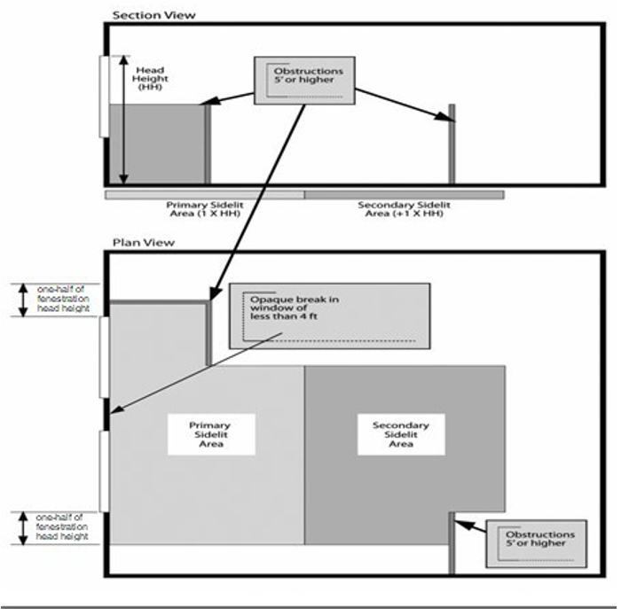
Figure C405.2.5.2(2)
Sidelit Daylight Zone Adjacent to Clerestory Fenestration in a Wall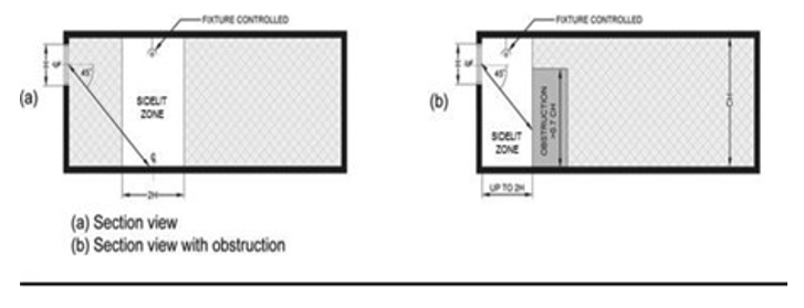
Figure C405.2.5.2(3)
Sidelit Daylight Zone Under a Sloped Rooftop Monitor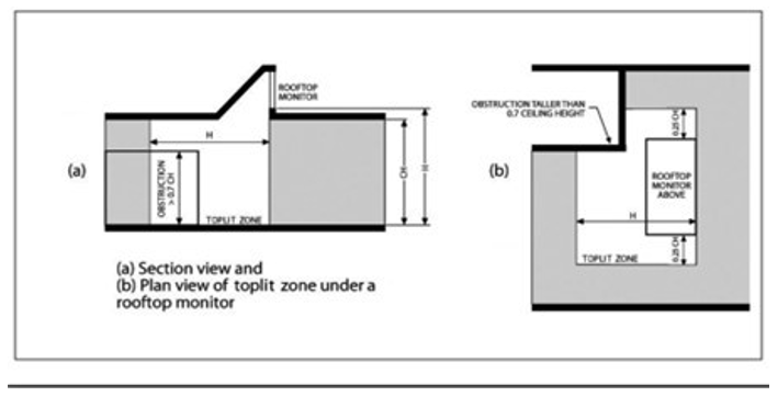
C405.2.5.3 Toplit daylight zone. The toplit daylight zone is the floor area underneath a roof fenestration assembly which complies with the following:
1. The toplit daylight zone shall extend laterally and longitudinally beyond the edge of the roof fenestration assembly to the nearest obstruction that is taller than 0.7 times the ceiling height, or up to 0.7 times the ceiling height, whichever is less, as indicated in Figure C405.2.5.3(1).
2. Where toplit daylight zones overlap with sidelit daylight zones, lights within the overlapping area shall be assigned to the toplit daylight zone.
3. The product of the visible transmittance of the roof fenestration assembly and the area of the rough opening of the roof fenestration assembly, divided by the area of the toplit daylight zone is no less than 0.008.
4. Where located under atrium fenestration, the toplit daylight zone shall include the bottom floor area directly beneath the atrium fenestration, and the top floor directly under the atrium fenestration, as indicated in Figure C405.2.5.3(4). The toplit daylight zone area at the top floor is calculated the same as for a toplit daylight zone. Intermediate levels below the top floor that are not directly beneath the atrium are not included.
Figure C405.2.5.3(1)
Toplit Daylight Zone Under a Rooftop Fenestration Assembly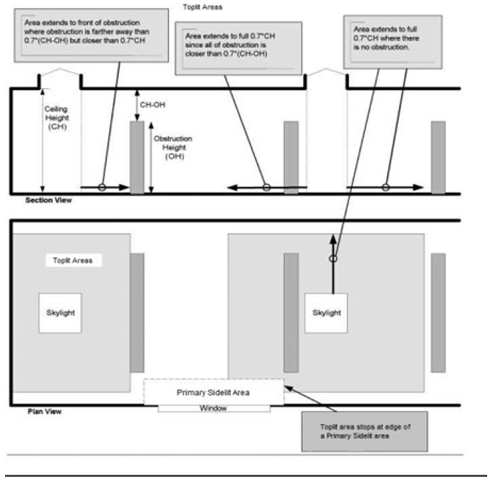
Figure C405.2.5.3(2)
Toplit Daylight Zone Under a Rooftop Monitor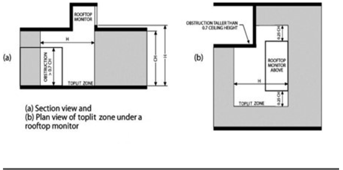
Figure C405.2.5.4
Toplit Daylight Zone Under Atrium Fenestration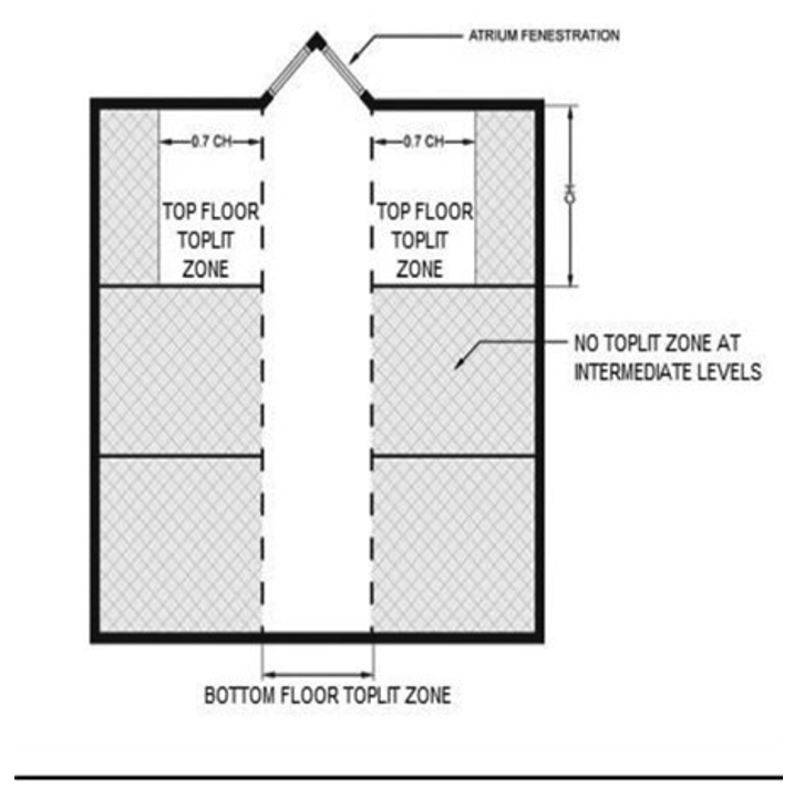
C405.2.5.4 Atriums. Daylight zones at atrium spaces shall be established at the top floor surrounding the atrium and at the floor of the atrium space, and not on intermediate floors, as indicated in Figure C405.2.5.4.
C405.2.6 Additional lighting controls. Specific application lighting shall be provided with controls, in addition to controls required by other sections, for the following:
1. The following lighting shall be controlled by an occupant sensor complying with Section C405.2.1.1 or a time switch control complying with Section C405.2.2.1. In addition, a manual control shall be provided to control such lighting separately from the general lighting in the space:
1.1. Luminaires for which additional lighting power is claimed in accordance with Section C405.4.2.2.1.
1.2. Display and accent.
1.3. Lighting in display cases.
1.4. Supplemental task lighting, including permanently installed under-shelf or under-cabinet lighting.
1.5. Lighting equipment that is for sale or demonstration in lighting education.
1.6. Display lighting for exhibits in galleries, museums and monuments that is in addition to general lighting.
2. Sleeping units shall have control device(s) or systems configured to automatically switch off all permanently installed luminaires and switched receptacles, including those installed within furniture, within 20 minutes after all occupants have left the unit.
EXCEPTIONS:
1. Lighting and switched receptacles controlled by card key controls.
2. Spaces where patient care is directly provided.
3. Lighting for life support of plants and animals and food warming, shall be controlled by a dedicated control that is independent of the controls for other lighting within the room or space.
4. Task lighting for medical and dental purposes that is in addition to general lighting shall be provided with a manual control.
5. Luminaires serving the exit access and providing means of egress illumination required by Section 1008.2 of the International Building Code, including luminaires that function as both normal and emergency means of egress illumination shall be controlled by a combination of listed emergency relay and occupancy sensors, or signal from another building control system, that automatically shuts off the lighting when the areas served by that illumination are unoccupied.
EXCEPTION: Means of egress illumination serving the exit access that does not exceed 0.01 watts per square foot (0.108 W/m2) of building area is exempt from this requirement.
C405.2.7 Area controls. The maximum lighting power that may be controlled from a single switch or automatic control device shall not exceed that which is provided by a 20 ampere circuit loaded to not more than 80 percent. A master control may be installed provided the individual switches retain their capability to function independently. Circuit breakers may not be used as the sole means of switching.
EXCEPTION: Areas less than 5 percent of the building footprint for footprints over 100,000 ft2.
C405.2.8 Advanced lighting controls. Any contiguous open office area larger than 5,000 square feet shall have its general lighting controlled by either:
1. Luminaire-level lighting controls (LLLC) conforming to the requirements of Section C405.2.8.1.
2. Networked lighting control (NLC) conforming to the requirements of Section C405.2.8.2.
C405.2.8.1 Luminaire-level lighting controls. Where luminaire-level lighting controls are required, they shall be configured to provide the controls or equivalent control function specified in Sections C405.2.1, C405.2.3, and C405.2.5. In addition, each LLLC luminaire shall be independently configured to:
1. Provide for continuous full range dimming.
2. Monitor occupant activity to brighten or dim lights when occupied or unoccupied, respectively.
3. Monitor ambient lighting, both electric and daylight, and brighten or dim artificial light to maintain desired light level. A maximum of 8 fixtures are permitted to be controlled together to maintain uniform light levels within a single daylight zone.
4. Allow configuration and reconfiguration of performance parameters for each control strategy including: High trim and low trim setpoints, timeouts, dimming fade rates, and sensor sensitivity adjustment.
5. Construction documents shall include a submittal of a sequence of operations including a specification outlining each of the functions required by this section.
6. Luminaires shall be configured with high end trim in accordance with Section C405.2.8.3.
C405.2.8.2 Networked lighting control (NLC). Where NLC are required, they shall be configured to provide controls and minimum function as specified in Section C405.2. In addition, each NLC luminaire shall be independently configured to:
1. Provide for continuous full range dimming.
2. Each luminaire shall be individually addressed.
EXCEPTIONS TO ITEM 2:
1. Multiple luminaires mounted on no more than 12 linear feet of a single lighting track and addressed as a single luminaire.
2. Multiple linear luminaires that are ganged together to create the appearance of a single longer fixture and addressed as a single luminaire, where the total length of the combined luminaires is not more than 12 feet.
3. Monitor occupant activity to brighten or dim lighting when occupied or unoccupied, respectively.
4. Monitor ambient lighting, both electric and daylight, and brighten or dim artificial light to maintain desired light level. A maximum of 8 fixtures are permitted to be controlled together to maintain uniform light levels within a single daylight zone.
5. Allow configuration and reconfiguration of performance parameters for each control strategy including: High trim and low trim setpoints, timeouts, dimming fade rates, and sensor sensitivity adjustment.
6. Allow for demand response load shed.
7. Construction documents shall include a submittal of a sequence of operations including a specification outlining each of the functions required by this section.
8. Luminaires shall be configured with high end trim in accordance with Section C405.2.8.3.
C405.2.8.3 High end trim. Luminaires subject to high end trim shall be initially configured with the following:
1. Programmed to limit the initial maximum lumen output or maximum lighting power to 85 percent or less of full light output or full power or to meet the target light level documented in project sequence of operations using the least amount of power.
2. High end trim power levels are allowed to automatically reset to accommodate lumen maintenance.
3. High end trim controls shall be accessible only to authorized personnel.
C405.2.9 Exterior lighting controls. Exterior lighting systems shall be provided with controls that comply with Sections C405.2.9.1 through C405.2.9.4.
EXCEPTIONS:
1. Lighting for covered vehicle entrances or exits from buildings or parking structures where required for safety, security or eye adaption.
2. Lighting controlled from within dwelling units.
C405.2.9.1 Daylight shutoff. Lights shall be configured to automatically turn off when daylight is present and satisfies the lighting needs.
C405.2.9.2 Building façade and landscape lighting. Building façade and landscaping lighting shall be configured to automatically shutoff for a minimum of 6 hours per night or from not later than 1 hour after business closing to not earlier than 1 hour before business opening, whichever is less.
EXCEPTION: Areas where an automatic shutoff would endanger safety or security.
C405.2.9.3 Lighting setback. Lighting that is not controlled in accordance with Section C405.2.9.2 shall comply with the following:
1. Luminaires serving outdoor parking areas and having a rated input wattage of greater than 40 watts and a mounting height of 24 feet (7315 mm) or less above the ground shall also be controlled so that the total wattage of such lighting is automatically reduced by not less than 50 percent during any time where activity has not been detected for 15 minutes or more. Not more than 1,500 watts of lighting power shall be controlled together.
2. All other lighting shall be controlled so that the total wattage of such lighting is automatically reduced by not less than 50 percent by selectively switching off or dimming luminaires at one of the following times:
2.1. From not later than 12 midnight to 6 a.m.
2.2. From not later than 1 hour after business closing to not earlier than 1 hour before business opening.
2.3. During any period when no activity has been detected for 15 minutes or more.
C405.2.9.4 Exterior time-switch control functions. Time-switch controls for exterior lighting shall comply with the following:
1. They shall have a clock capable of being programmed for not fewer than 7 days.
2. They shall be capable of being set for 7 different day types per week.
3. They shall incorporate an automatic holiday setback feature.
4. They shall have program backup capabilities that prevent the loss of program and time settings for a period of at least 10 hours in the event that power is interrupted.
C405.2.10 Parking garage lighting control. Parking garage lighting shall be controlled by an occupant sensor complying with Section C405.2.1.1 or a time-switch control complying with Section C405.2.2.1. Additional lighting controls shall be provided as follows:
1. Lighting power of each luminaire shall be automatically reduced by not less than 30 percent when there is no activity detected within a lighting zone for 20 minutes. Lighting zones for this requirement shall be not larger than 3,600 square feet (334.5 m2).
2. Where lighting for eye adaptation is provided at covered vehicle entrances and exits from buildings and parking structures, such lighting shall be separately controlled by a device that automatically reduces lighting power by at least 50 percent from sunset to sunrise.
3. The power to luminaires within 20 feet (6096 mm) of perimeter wall openings shall automatically reduce in response to daylight by at least 50 percent.
EXCEPTIONS TO ITEM 3:
1. Daylight transition lighting for covered vehicle entrances and exits from buildings and parking structures; each transition zone shall not exceed a depth of 66 feet inside the structure and a width of 50 feet.
2. Where permanent screens or architectural elements obstruct more than 50 percent of the opening.
3. Where the top of any existing adjacent structure or natural object is at least twice as high above the openings as its horizontal distance from the opening.
C405.3 Lighting for plant growth and maintenance. In Group F, Group U, and controlled plant growth environments, all permanently installed luminaires used for plant growth and maintenance shall have a photosynthetic photon efficacy measured at the lamp for luminaires with serviceable or removable lamps or at the luminaire for integrated, nonserviceable luminaires of not less than 1.7 µmol/J for greenhouses and not less than 1.9 µmol/J for all other indoor growing spaces as defined in accordance with ANSI/ASABE S640.
EXCEPTION: Buildings with no more than 10 kW of aggregate horticultural lighting load.
Luminaires used for the growth and maintenance of plants for decorative purposes, in spaces not primarily used for horticulture, shall have a photosynthetic photon efficacy measured at the luminaire of not less than 1.4 µmol/J.
C405.4 Interior lighting power requirements. A building complies with this section if its total connected interior lighting power calculated under Section C405.4.1 is no greater than the interior lighting power allowance calculated under Section C405.4.2.
C405.4.1 Total connected interior lighting power. The total connected interior lighting power shall be determined in accordance with Equation 4-13.
|
TCLP = [LVL + BLL + TRK + POE + Other] |
(Equation 4-13) |
Where:
|
TCLP |
= |
Total connected lighting power (watts). |
|
LVL |
= |
For luminaires with lamps connected directly to building power, such as line voltage lamps, the rated wattage of the lamp, which must be minimum 60 lumens/watt. |
|
BLL |
= |
For luminaires incorporating a ballast or transformer, the rated input wattage of the ballast or transformer when operating the lamp. |
|
TRK |
= |
For lighting track, cable conductor, rail conductor and plug-in busway systems that allow the addition and relocation of luminaires without rewiring, the wattage shall be one of the following: 1. The specified wattage of the luminaires, but not less than 16 W/lin. ft. (52 W/lin. m). 2. The wattage limit of the permanent current limiting devices protecting the system. 3. The wattage limit of the transformer supplying the system. |
|
POE |
= |
For other modular lighting systems served with power supplied by a driver, power supply for transformer including, but not limited to, low-voltage lighting systems, the wattage of the system shall be the maximum rated input wattage of the driver, power supply or transformed published in the manufacturer’s catalogs, as specified by UL 2108 or 8750. For power-over-Ethernet lighting systems, power provided to installed nonlighting devices may be subtracted from the total power rating of the power-over-Ethernet systems. |
|
Other |
= |
The wattage of all other luminaires and lighting, sources not covered above and associated with interior lighting verified by data supplied by the manufacturer or other approved sources. |
The connected power associated with the following lighting equipment is not included in calculating total connected lighting power.
1. Television broadcast lighting for playing areas in sports arenas.
2. Emergency lighting automatically off during normal building operation.
3. Lighting in spaces specifically designed for use by occupants with special lighting needs including those with visual impairment and other medical and age-related issues.
4. Casino gaming areas.
5. General area lighting power in industrial and manufacturing occupancies dedicated to the inspection or quality control of goods and products.
6. Mirror lighting in dressing rooms.
7. Task lighting for medical and dental purposes that is in addition to general lighting.
8. Display lighting for exhibits in galleries, museums and monuments that is in addition to general lighting.
9. Lighting for theatrical purposes, including performance, stage, film production and video production.
10. Lighting for photographic processes.
11. Lighting integral to equipment or instrumentation and installed by the manufacturer.
12. Lighting provided exclusively for plant growth and maintenance, in spaces other than Group F, Group U, or controlled plant growth environments, where controlled separately from general lighting using an automatic time clock system, with rated fixture efficacy in compliance with Section C405.3.
13. Advertising signage or directional signage.
14. Lighting for food warming.
15. Lighting equipment that is for sale.
16. Lighting demonstration equipment in lighting education facilities.
17. Lighting approved because of safety considerations.
18. Lighting in retail display windows, provided the display area is enclosed by ceiling-height partitions.
19. Furniture mounted supplemental task lighting that is controlled by automatic shutoff.
20. Exit signs.
21. Lighting used for aircraft painting.
22. Antimicrobial lighting used for the sole purpose of disinfecting a space.
C405.4.2 Interior lighting power allowance. The total interior lighting power allowance (watts) for an entire building shall be determined according to Table C405.4.2(1) using the Building Area Method, or Table C405.4.2(2) using the Space-by-Space Method. The interior lighting power allowance for projects that involve only portions of a building shall be determined according to Table C405.4.2(2) using the Space-by-Space Method. Buildings with unfinished spaces shall use the Space-by-Space Method.
C405.4.2.1 Building area method. For the Building Area Method, the interior lighting power allowance is calculated as follows:
1. For each building area type inside the building, determine the applicable building area type and the allowed lighting power density for that type from Table C405.4.2(1). For building area types not listed, select the building area type that most closely represents the use of that area. For the purposes of this method, an “area” shall be defined as all contiguous spaces that accommodate or are associated with a single building area type.
2. Determine the floor area for each building area type listed in Table C405.4.2(1) and multiply this area by the applicable value from Table C405.4.2(1) to determine the lighting power (watts) for each building area type.
3. The total interior lighting power allowance (watts) for the entire building is the sum of the lighting power from each building area type.
C405.4.2.2 Space-by-Space Method. Where a building has a space designated as unfinished, neither the area nor the lighting power in the space shall be calculated as part of the LPA. For the Space-by-Space Method, the interior lighting power allowance is calculated as follows:
1. For each area enclosed by partitions that are not less than 80 percent of the ceiling height determine the applicable space type from Table C405.4.2(2). For space types not listed, select the space type that most closely represents the proposed use of the space. Where a space has multiple functions, that space shall be broken up into smaller subspaces, each using their own space type. If an entire space has multiple functions that necessitate a higher lighting power allowance in order to serve one of the primary functions, the higher allowance is permitted to be used.
2. Determine the total floor area of all of the spaces of each space type and multiply by the value for the space type in Table C405.4.2(2) to determine the lighting power (watts) for each space type.
3. The total interior lighting power allowance (watts) shall be the sum of the lighting power allowances for all space types.
C405.4.2.2.1 Additional interior lighting power. Where using the Space-by-Space Method, an increase in the interior lighting power allowance is permitted for specific lighting functions. Additional power shall be permitted only where the specified lighting is installed in addition to and automatically controlled separately from general lighting, in accordance with Section C405.2.6. This additional power shall be used only for the specified luminaires and shall not be used for any other purpose.
An increase in the interior lighting power allowance is permitted for lighting equipment to be installed in sales areas specifically to highlight merchandise. The additional lighting power shall be determined in accordance with Equation 4-14.
|
Additional Interior Lighting Power Allowance = 500 watts + (Retail Area 1 × 0.45 W/ft2) + (Retail Area 2 × 0.45 W/ft2) + (Retail Area 3 × 1.05 W/ft2) + (Retail Area 4 × 1.87 W/ft2) |
(Equation 4-14) |
Where:
|
Retail Area 1 |
= |
The floor area for all products not listed in Retail Area 2, 3 or 4. |
|
Retail Area 2 |
= |
The floor area used for the sale of vehicles, sporting goods and small electronics. |
|
Retail Area 3 |
= |
The floor area used for the sale of furniture, clothing, cosmetics and artwork. |
|
Retail Area 4 |
= |
The floor area used for the sale of jewelry, crystal and china. |
EXCEPTION: Other merchandise categories are permitted to be included in Retail Areas 2 through 4, provided that justification documenting the need for additional lighting power based on visual inspection, contrast, or other critical display requirement is approved by the code official.
|
Building Area Type |
LPD (w/ft2) |
|---|---|
|
Automotive facility |
0.69 |
|
Convention center |
0.61 |
|
Court house |
0.71 |
|
Dining: Bar lounge/leisure |
0.70 |
|
Dining: Cafeteria/fast food |
0.67 |
|
Dining: Family |
0.62 |
|
Dormitory |
0.49 |
|
Exercise center |
0.68 |
|
Fire station |
0.53 |
|
Gymnasium |
0.71 |
|
Health care clinic |
0.77 |
|
Hospital |
0.92 |
|
Hotel/motel |
0.50 |
|
Library |
0.79 |
|
Manufacturing facility |
0.78 |
|
Motion picture theater |
0.41 |
|
Multifamilyc |
0.44 |
|
Museum |
0.53 |
|
Office |
0.59 |
|
Parking garage |
0.16 |
|
Penitentiary |
0.65 |
|
Performing arts theater |
0.78 |
|
Police station |
0.59 |
|
Post office |
0.61 |
|
Religious building |
0.63 |
|
Retail |
0.74 |
|
School/university |
0.67 |
|
Sports arena |
0.69 |
|
Town hall |
0.64 |
|
Transportation |
0.53 |
|
Warehouse |
0.43 |
|
Workshop |
0.82 |
a. Where sleeping units are excluded from lighting power calculations by application of Section R404.1, neither the area of the sleeping units nor the wattage of lighting in the sleeping units is counted.
b. Where dwelling units are excluded from lighting power calculations by application of Section R404.1, neither the area of the dwelling units nor the wattage of lighting in the dwelling units is counted.
c. Dwelling units are excluded. Neither the area of the dwelling units nor the wattage of lighting in the dwelling units is counted.
|
Common Space-by-Space Typesa |
LPD (w/ft2) |
|
|---|---|---|
|
Atrium - Less than 20 feet in height |
0.30 |
|
|
Atrium - 20 to 40 feet in height |
0.39 |
|
|
Atrium - Above 40 feet in height |
0.48 |
|
|
Audience/seating area - Permanent |
|
|
|
|
In an auditorium |
0.54 |
|
|
In a gymnasium |
0.22 |
|
|
In a motion picture theater |
0.26 |
|
|
In a penitentiary |
0.56 |
|
|
In a performing arts theater |
1.04 |
|
|
In a religious building |
0.68 |
|
|
In a sports arena |
0.26 |
|
|
Otherwise |
0.22 |
|
Banking activity area i |
|
|
|
Breakroom (see lounge/breakroom) |
|
|
|
Classroom/lecture hall/training room |
|
|
|
|
In a penitentiary |
0.74 |
|
|
Otherwise h |
0.68 |
|
Computer room, data center |
0.71 |
|
|
Conference/meeting/multipurpose |
0.84 |
|
|
Copy/print room |
0.53 |
|
|
Corridor |
|
|
|
|
In a facility for the visually impaired (and not used primarily by the staff)b |
0.71 |
|
|
In a hospital |
0.61 |
|
|
Otherwisec, k |
0.42 |
|
Courtroomc |
1.03 |
|
|
Dining area |
|
|
|
|
In a penitentiary |
0.35 |
|
|
In a facility for the visually impaired (and not used primarily by the staff)b |
1.22 |
|
|
In a bar/lounge or leisure dining i |
0.72 |
|
|
In cafeteria or fast food dining |
0.34 |
|
|
In a family dining arean |
0.49 |
|
|
Otherwise |
0.40 |
|
Electrical/mechanical |
0.64 |
|
|
Emergency vehicle garage |
0.48 |
|
|
Food preparation |
1.13 |
|
|
Laboratory |
|
|
|
|
In or as a classroom |
1.00 |
|
|
Otherwise |
1.14 |
|
Laundry/washing area |
0.48 |
|
|
Loading dock, interior |
0.83 |
|
|
Lobbyc |
|
|
|
|
In a facility for the visually impaired (and not used primarily by the staff)b |
1.44 |
|
|
For an elevator |
0.61 |
|
|
In a hotel |
0.46 |
|
|
In a motion picture theater |
0.19 |
|
|
In a performing arts theater |
1.14 |
|
|
Otherwise |
0.76 |
|
Locker room |
0.41 |
|
|
Lounge/breakroom i |
|
|
|
|
In a health care facility c, i |
0.77 |
|
|
Otherwise i |
0.52 |
|
Office |
|
|
|
|
Enclosed |
0.69 |
|
|
Open plan |
0.53 |
|
Parking area, interior |
0.10 |
|
|
Pharmacy area |
1.59 |
|
|
Restroom |
|
|
|
|
In a facility for the visually impaired (and not used primarily by the staff)b |
0.96 |
|
|
Otherwise i |
0.70 |
|
Sales area |
0.81 |
|
|
Seating area, general |
0.20 |
|
|
Security screening general area |
0.64 |
|
|
Security screening in transportation facilities |
0.93 |
|
|
Security screening transportation waiting area |
0.56 |
|
|
Stairwell c, i |
0.45 |
|
|
Storage room |
|
|
|
|
< 50 ft2 |
0.47 |
|
|
50-100 ft2 |
|
|
|
All other storage |
0.33 |
|
Vehicular maintenance |
0.56 |
|
|
Workshop |
1.11 |
|
|
Building Specific Space-by-Space Typesa |
|
|
|
Automotive (see vehicular maintenance) |
|
|
|
Convention center - Exhibit space |
0.48 |
|
|
Facility for the visually impairedb |
|
|
|
|
In a chapel (and not used primarily by the staff)b |
0.58 |
|
|
In a recreation room (and not used primarily by the staff)b |
1.20 |
|
Gaming establishments |
|
|
|
|
High limits game |
1.60 |
|
|
Slots |
0.51 |
|
|
Sportsbook |
0.78 |
|
|
Table games |
1.04 |
|
Gymnasium/fitness center |
|
|
|
|
In an exercise area |
0.78 |
|
|
In a playing area |
0.78 |
|
Health care facilityc, i |
|
|
|
|
In an exam/treatment room |
1.33 |
|
|
In an imaging room |
0.94 |
|
|
In a medical supply room |
0.56 |
|
|
In a nursery |
0.87 |
|
|
In a nurse’s station |
1.07 |
|
|
In an operating room |
2.26 |
|
|
In a physical therapy room |
0.82 |
|
|
In a recovery room |
1.18 |
|
|
In a telemedicine room |
1.44 |
|
Library |
|
|
|
|
In a reading area i |
0.82 |
|
|
In the stacks |
1.12 |
|
Manufacturing facility |
|
|
|
|
In a detailed manufacturing area |
0.71 |
|
|
In an equipment room |
0.69 |
|
|
In an extra high bay area (greater than 50-foot floor-to-ceiling height) |
1.29 |
|
|
In a high bay area (25 - 50-foot floor-to-ceiling height) |
1.18 |
|
|
In a low bay (< 25-foot floor-to-ceiling height) |
0.81 |
|
Museum |
|
|
|
|
In a general exhibition areai |
0.29 |
|
|
In a restoration room |
1.18 |
|
Performing arts theater dressing/fitting room |
0.37 |
|
|
Post office - Sorting area |
0.67 |
|
|
Religious buildings |
|
|
|
|
In a fellowship hall i |
0.48 |
|
|
In a worship/pulpit/choir area i |
0.71 |
|
Retail facilities |
|
|
|
|
In a dressing/fitting room |
0.43 |
|
|
Hair salon |
0.62 |
|
|
Nail salon |
0.71 |
|
|
In a mall concourse |
0.54 |
|
|
Massage space |
0.77 |
|
Sports arena - Playing area |
|
|
|
|
For a Class 1 facility d |
2.72 |
|
|
For a Class 2 facility e |
1.88 |
|
|
For a Class 3 facility f |
1.23 |
|
|
For a Class 4 facility g |
0.81 |
|
Sports arena - Pools |
|
|
|
|
For a Class 1 facilityi |
2.09 |
|
|
For a Class 2 facilityj |
1.40 |
|
|
For a Class 3 facilityk |
0.94 |
|
|
For a Class 4 facilityl |
0.56 |
|
Transportation |
|
|
|
|
Airport Hangar |
1.29 |
|
|
In a baggage/carousel area |
0.27 |
|
|
In an airport concourse |
0.47 |
|
|
At a terminal ticket counter i |
0.38 |
|
|
Passenger loading area |
0.67 |
|
Warehouse - Storage area |
|
|
|
|
For medium to bulky palletized items |
0.31 |
|
|
For smaller, hand-carried items |
0.66 |
For SI: 1 foot = 304.8 mm, 1 watt per square foot = 10.76 w/m2.
a. In cases where both a common space type and a building area specific space type are listed, the building area specific space type shall apply.
b. A ‘Facility for the Visually Impaired’ is a facility that is licensed or will be licensed by local or state authorities for senior long-term care, adult daycare, senior support or people with special visual needs.
c. Additional lighting power allowance of 0.2 watts per square foot for the purpose of highlighting art or exhibits. This additional power shall be permitted only where the specified lighting is installed in addition to and controlled separately from general lighting in accordance with Section C405.2.6. This additional power shall be used only for the specified luminaires, shall not be used for any other purpose, and shall not be added to any other space or the interior power allowance.
d. Reserved.
e. Reserved.
f. Reserved.
g. Where sleeping units are excluded from lighting power calculations by application of Section R404.1, neither the area of the sleeping units nor the wattage of lighting in the sleeping units is counted.
h. Where dwelling units are excluded from lighting power calculations by application of Section R404.1, neither the area of the dwelling units nor the wattage of lighting in the dwelling units is counted.
i. Class I facilities consist of professional facilities; and semiprofessional, collegiate, or club facilities with seating for 5,000 or more spectators.
j. Class II facilities consist of collegiate and semiprofessional facilities with seating for fewer than 5,000 spectators; club facilities with seating for between 2,000 and 5,000 spectators; and amateur league and high school facilities with seating for more than 2,000 spectators.
k. Class III facilities consist of club, amateur league and high school facilities with seating for 2,000 or fewer spectators.
l. Class IV facilities consist of elementary school and recreational facilities; and amateur league and high school facilities without provision for spectators.
m. For classrooms, additional lighting power allowance of 4.50 W/ lineal foot of white or chalk boards for directional lighting dedicated to white or chalk boards.
n. Additional lighting power allowance of 0.15 W/ft2 for ornamental lighting. Qualifying ornamental lighting includes luminaires that are specifically used in a decorative manner. This additional power shall be permitted only where the specified lighting is installed in addition to and controlled separately from display or general lighting in accordance with Section C405.2.6. This additional power shall be used only for the specified luminaires and it shall not be added to any other space or the interior power allowance.
o. For scientific laboratories, additional lighting power allowance of 0.35 Watts per square foot for specialized task work - lighting that provides for small-scale, cognitive or fast performance visual tasks; lighting required for operating specialized equipment associated with pharmaceutical/laboratorial activities.
p. For offices, additional lighting power allowance of 0.20 W/square foot for portable lighting, which includes under shelf or furniture-mounted supplemental task lighting qualifies when controlled by a time clock or an occupancy sensor
q. Where a space is designated as unfinished, neither the area nor the lighting power in the space shall be calculated as part of the LPA.
r. For corridors, additional lighting power allowance of 0.25 W/square foot for display lighting and decorative lighting is permitted where provided for aesthetic purposes. Decorative lighting fixtures in corridors are also permitted to provide general lighting.
C405.5 Exterior lighting power requirements. The total connected exterior lighting power calculated in accordance with Section C405.5.2 shall not be greater than the exterior lighting power allowance calculated in accordance with Section C405.5.3.
C405.5.1 Exterior building grounds lighting. All exterior building grounds luminaires that operate at greater than 25 watts shall have a minimum efficacy of 100 lumens per watt.
EXCEPTIONS:
1. Luminaires controlled by a motion sensor.
2. Luminaires that qualify for one of the exceptions under Section C405.5.2.
C405.5.2 Total connected exterior building lighting power. The total exterior connected lighting power shall be the total maximum rated wattage of all exterior lighting that is powered through the energy service for the building.
EXCEPTION: Lighting used for the following applications shall not be included:
1. Lighting approved because of safety considerations;
2. Emergency lighting automatically off during normal business operation;
3. Exit signs;
4. Specialized signal, directional and marker lighting associated with transportation;
5. Advertising signage or directional signage;
6. Integral to equipment or instrumentation and is installed by its manufacturer;
7. Theatrical purposes, including performance, stage, film production and video production;
8. Athletic playing areas;
9. Temporary lighting;
10. Industrial production, material handling, transportation sites and associated storage areas;
11. Theme elements in theme/amusement parks;
12. Lighting integrated within or used to highlight features of art, public monuments and the national flag;
13. Lighting for water features and swimming pools; and
14. Lighting that is controlled from within dwelling units, where the lighting complies with Section R404.1.
C405.5.3 Exterior lighting power allowance. The exterior lighting power allowance (watts) is calculated as follows:
1. Determine the Lighting Zone (LZ) for the building according to Table C405.5.3(1), unless otherwise specified by the code official.
2. For each exterior area that is to be illuminated by lighting that is powered through the energy service for the building, determine the applicable area type from Table C405.5.3(2). For area types not listed, select the area type that most closely represents the proposed use of the area. Covered parking garage lighting is not considered exterior lighting for the purposes of this calculation.
3. Determine the total area or length of each area type and multiply by the value for the area type in Table C405.5.3(2) to determine the lighting power (watts) allowed for each area type.
4. The total exterior lighting power allowance (watts) is the sum of the base site allowance determined according to Table C405.5.3(2), plus the watts from each area type.
C405.5.3.1 Additional exterior lighting power. Additional exterior lighting power allowances are available for the specific lighting applications listed in Table C405.5.3(3). These additional power allowances shall be used only for the luminaires serving these applications and shall not be used to increase any other lighting power allowance.
|
Lighting zone |
Description |
|---|---|
|
1 |
Developed areas of national parks, state parks, forest land, and rural areas |
|
2 |
Areas predominantly consisting of residential zoning, neighborhood business districts, light industrial with limited nighttime use and residential mixed us areas |
|
3 |
All other areas no classified as lighting zone 1 or 2 |
|
4 |
Not used |
|
|
Lighting Zones |
||
|---|---|---|---|
|
|
Zone 1 |
Zone 2 |
Zone 3 |
|
Base Site Allowance |
160 W |
280 W |
400 W |
|
Uncovered Parking Areas |
|||
|
Parking areas and drives |
0.015 W/ft2 |
0.026 W/ft2 |
0.037 W/ft2 |
|
Building Grounds |
|||
|
Walkways and ramps less than 10 feet wide |
0.04 W/ft2 |
0.07 W/ft2 |
0.10 W/ft2 |
|
Walkways and ramps 10 feet wide or greater, plaza areas, special feature areas |
0.04 W/ft2 |
0.07 W/ft2 |
0.10 W/ft2 |
|
Dining areas |
0.156 W/ft2 |
0.273 W/ft2 |
0.390 W/ft2 |
|
Stairways |
Exempt |
Exempt |
Exempt |
|
Pedestrian tunnels |
0.063 W/ft2 |
0.110 W/ft2 |
0.157 W/ft2 |
|
Landscaping |
0.014 W/ft2 |
0.025 W/ft2 |
0.036 W/ft2 |
|
Building Entrances and Exits |
|||
|
Pedestrian and vehicular entrances and exits |
5.6 W/linear foot of opening |
9.8 W/linear foot of opening |
14.0 W/linear foot of opening |
|
Entry canopies |
0.072 W/ft2 |
0.126 W/ft2 |
0.180 W/ft2 |
|
Loading docks |
0.104 W/ft2 |
0.182 W/ft2 |
0.260 W/ft2 |
|
Sales Canopies |
|||
|
Free standing and attached |
0.20 W/ft2 |
0.35 W/ft2 |
0.50 W/ft2 |
|
Outdoor Sales |
|||
|
Open areas (including vehicle sales lots) |
0.072 W/ft2 |
0.126 W/ft2 |
0.180 W/ft2 |
|
Street frontage for vehicle sales lots in addition to “open area” allowance |
No Allowance |
7 W/linear foot |
10.3 W/linear foot |
For SI: 1 foot = 304.8 mm, 1 watt per square foot = 10.76 W per m2
|
|
Zone 1 |
Zone 2 |
Zone 3 |
|---|---|---|---|
|
Building façade |
No allowance |
0.075 W/ft2 of gross above-grade wall area |
0.113 W/ft2 of gross above-grade wall area |
|
Automated teller machines (ATM) and night depositories |
80 W per location plus 25 per additional ATM |
80 W per location plus 25 per additional ATM |
80 W per location plus 25 per additional ATM |
|
Uncovered entrances and gatehouse inspection stations at guarded facilities |
0.144 W/ft2 |
0.252 W/ft2 |
0.360 W/ft2 |
|
Uncovered loading areas for law enforcement, fire, ambulance and other emergency service vehicles |
0.104 W/ft2 |
0.182 W/ft2 |
0.260 W/ft2 |
|
Drive-up windows/doors |
53 W per drive through |
92 W per drive through |
132 W per drive through |
|
Parking near 24-hour retail entrances |
80 W per main entry |
140 W per main entry |
200 W per main entry |
C405.5.3.1 Additional exterior lighting power. Any increase in the exterior lighting power allowance is limited to the specific lighting applications indicated in Table C405.5.3(3). The additional power shall be used only for the luminaires that are serving these applications and shall not be used for any other purpose.
C405.5.4 Gas lighting. Gas-fired lighting appliances shall not be equipped with continuously burning pilot ignition systems.
C405.5.5 Full cutoff luminaires. For open parking and outdoor areas and roadways, luminaires mounted more than 15 feet above the ground shall have a luminaire light distribution in which zero candela intensity occurs at an angle of 90 degrees above nadir, and all greater angles from nadir.
C405.6 Electrical transformers. Low-voltage dry-type distribution electric transformers shall meet the minimum efficiency requirements of Table C405.6 as tested and rated in accordance with the test procedure listed in DOE 10 C.F.R. 431. The efficiency shall be verified through certification under an approved certification program or, where no certification program exists, the equipment efficiency ratings shall be supported by data furnished by the transformer manufacturer.
EXCEPTION: The following transformers are exempt:
1. Transformers that meet the Energy Policy Act of 2005 exclusions based on the DOE 10 C.F.R. 431 definition of special purpose applications.
2. Transformers that meet the Energy Policy Act of 2005 exclusions that are not to be used in general purpose applications based on information provided in DOE 10 C.F.R. 431.
3. Transformers that meet the Energy Policy Act of 2005 exclusions with multiple voltage taps where the highest tap is not less than 20 percent more than the lowest tap.
4. Drive transformers.
5. Rectifier transformers.
6. Auto-transformers.
7. Uninterruptible power system transformers.
8. Impedance transformers.
9. Regulating transformers.
10. Sealed and nonventilating transformers.
11. Machine tool transformer.
12. Welding transformer.
13. Grounding transformer.
14. Testing transformer.
|
Single Phase Transformers |
Three Phase Transformers |
||
|---|---|---|---|
|
kVAa |
Efficiency (%)b |
kVAa |
Efficiency (%)b |
|
15 |
97.70 |
15 |
97.89 |
|
25 |
98.00 |
30 |
98.23 |
|
37.5 |
98.20 |
45 |
98.40 |
|
50 |
98.30 |
75 |
98.60 |
|
75 |
98.50 |
112.5 |
98.74 |
|
100 |
98.60 |
150 |
98.83 |
|
167 |
98.70 |
225 |
98.94 |
|
250 |
98.80 |
300 |
99.02 |
|
333 |
98.90 |
500 |
99.14 |
|
|
|
750 |
99.23 |
|
|
|
1000 |
99.28 |
a kiloVolt-Amp rating.
b Nominal efficiencies shall be established in accordance with the DOE 10 C.F.R. 431 test procedure for low voltage dry-type transformers.
C405.7 Dwelling unit electrical energy consumption. Each dwelling unit located in a Group R-2 building shall have a separate electrical meter. A utility tenant meter meets this requirement. See Section C409 for additional requirements for energy metering and energy consumption management.
EXCEPTION: Dwelling units in other than Group R-2 multi-family and live/work units are not required to provide a separate electrical metering at each dwelling unit where electrical usage is metered separately for each of the following building end uses:
1. Dwelling units.
2. Sleeping units.
3. Commercial kitchens.
4. Central laundries.
C405.7.1 Electric receptacles at dwelling unit gas appliances. Where dwelling unit appliances are served by natural gas, an electrical receptacle or junction box and circuit shall be provided at each gas appliance with sufficient capacity to serve a future electric appliance in the same location. The receptacles and circuits shall be included in the electrical service load calculation and shall meet the requirements of items 1 through 3 below. The receptacle or junction box for each gas appliance shall be located within 12 inches of the appliance and without obstructions between the appliance and the outlet. An electric receptacle is not required for a decorative gas fireplace.
1. Each gas range, cooktop, or oven, or combination appliance, location shall be served by a dedicated 240/208-volt, 40-amp receptacle connected to the dwelling unit electric panel with a 3-conductor branch circuit complying with 210.19(A)(3) of the NEC as adopted by Washington state and a minimum included load of 9600 VA for 240-volt systems or 8000 VA for 208-volt systems.
2. Each gas clothes dryer location shall be served by a dedicated 240/208-volt, 30-amp receptacle connected to the dwelling unit electric panel with a 3-conductor branch circuit and a minimum included load of 5000 VA.
3. The location of each gas domestic water heater installed within a dwelling unit shall be served by a dedicated 240/208-volt, 30-amp junction box connected to the dwelling unit electrical panel with a 3-conductor branch circuit and a minimum included load of 4500 VA.
C405.8 Electric motor efficiency. All electric motors, fractional or otherwise, shall meet the minimum efficiency requirements of Tables C405.8(1) through C405.8(4) when tested and rated in accordance with DOE 10 CFR. The efficiency shall be verified through certification under an approved certification program, or, where no certification program exists, the equipment efficiency rating shall be supported by data furnished by the motor manufacturer.
EXCEPTION: The standards in this section shall not apply to the following exempt electric motors.
1. Air-over electric motors.
2. Component sets of an electric motor.
3. Liquid-cooled electric motors.
4. Submersible electric motors.
5. Inverter-only electric motors.
6. Mechanical ventilation system types with an input power less than 746 watts that comply with the requirements of Section C403.8.4.
Fractional hp fan motors that are 1/12 hp or greater and less than 1 hp (based on output power) which are not covered by Tables C405.8(3) and C405.8(4) shall be electronically commutated motors or shall have a minimum motor efficiency of 70 percent when rated in accordance with DOE 10 CFR 431. These motors shall also have the means to adjust motor speed for either balancing or remote control. Belt-driven fans may use sheave adjustment for airflow balancing in lieu of a varying motor speed.
EXCEPTIONS:
1. Motors that are an integral part of specialized process equipment.
2. Where the motor is integral to a listed piece of equipment for which no complying motor has been approved.
3. Motors used as a component of the equipment meeting the minimum efficiency requirements of Section C403.3.2 and Tables C403.3.2(1) through C403.3.2(16), provided that the motor input is included when determining the equipment efficiency.
4. Motors in the airstream within fan coils and terminal units that operate only when providing heating to the space served.
5. Mechanical ventilation system types with an input power less than 746 watts that comply with the requirements of Section C403.8.4.
6. Domestic clothes dryer booster fans, range hood exhaust fans, and domestic range booster fans that operate intermittently.
7. Radon and contaminated soil exhaust fans.
|
Motor horsepower (Standard kilowatt equivalent) |
Nominal full-load efficiency (%) as of June 1, 2016 |
|||||||
|---|---|---|---|---|---|---|---|---|
|
2 pole |
4 pole |
6 pole |
8 pole |
|||||
|
Enclosed |
Open |
Enclosed |
Open |
Enclosed |
Open |
Enclosed |
Open |
|
|
1 (0.75) |
77.0 |
77.0 |
85.5 |
85.5 |
82.5 |
82.5 |
75.5 |
75.5 |
|
1.5 (1.1) |
84.0 |
84.0 |
86.5 |
86.5 |
87.5 |
86.5 |
78.5 |
77.5 |
|
2 (1.5) |
85.5 |
85.5 |
86.5 |
86.5 |
88.5 |
87.5 |
84.0 |
86.5 |
|
3 (2.2) |
86.5 |
85.5 |
89.5 |
89.5 |
89.5 |
88.5 |
85.5 |
87.5 |
|
5 (3.7) |
88.5 |
86.5 |
89.5 |
89.5 |
89.5 |
89.5 |
86.5 |
88.5 |
|
7.5 (5.5) |
89.5 |
88.5 |
91.7 |
91.0 |
91.0 |
90.2 |
86.5 |
89.5 |
|
10 (7.5) |
90.2 |
89.5 |
91.7 |
91.7 |
91.0 |
91.7 |
89.5 |
90.2 |
|
15 (11) |
91.0 |
90.2 |
92.4 |
93.0 |
91.7 |
91.7 |
89.5 |
90.2 |
|
20 (15) |
91.0 |
91.0 |
93.0 |
93.0 |
91.7 |
92.4 |
90.2 |
91.0 |
|
25 (18.5) |
91.7 |
91.7 |
93.6 |
93.6 |
93.0 |
93.0 |
90.2 |
91.0 |
|
30 (22) |
91.7 |
91.7 |
93.6 |
94.1 |
93.0 |
93.6 |
91.7 |
91.7 |
|
40 (30) |
92.4 |
92.4 |
94.1 |
94.1 |
94.1 |
94.1 |
91.7 |
91.7 |
|
50 (37) |
93.0 |
93.0 |
94.5 |
94.5 |
94.1 |
94.1 |
92.4 |
92.4 |
|
60 (45) |
93.6 |
93.6 |
95.0 |
95.0 |
94.5 |
94.5 |
92.4 |
93.0 |
|
75 (55) |
93.6 |
93.6 |
95.4 |
95.0 |
94.5 |
94.5 |
93.6 |
94.1 |
|
100 (75) |
94.1 |
93.6 |
95.4 |
95.4 |
95.0 |
95.0 |
93.6 |
94.1 |
|
125 (90) |
95.0 |
94.1 |
95.4 |
95.4 |
95.0 |
95.0 |
94.1 |
94.1 |
|
150 (110) |
95.0 |
94.1 |
95.8 |
95.8 |
95.8 |
95.4 |
94.1 |
94.1 |
|
200 (150) |
95.4 |
95.0 |
96.2 |
95.8 |
95.8 |
95.4 |
94.5 |
94.1 |
|
250 (186) |
95.8 |
95.0 |
96.2 |
95.8 |
95.8 |
95.8 |
95.0 |
95.0 |
a Nominal efficiencies shall be established in accordance with DOE 10 C.F.R. 431.
b For purposes of determining the required minimum nominal full-load efficiency of an electric motor that has a horsepower or kilowatt rating between two horsepower or two kilowatt ratings listed in this table, each such motor shall be deemed to have a listed horsepower or kilowatt rating, determined as follows:
1. A horsepower at or above the midpoint between the two consecutive horsepowers shall be rounded up to the higher of the two horsepowers.
2. A horsepower below the midpoint between the two consecutive horsepowers shall be rounded down to the lower of the two horsepowers.
3. A kilowatt rating shall be directly converted from kilowatts to horsepower using the formula 1 kW = (1/0.746) horsepower. The conversion should be calculated to three significant decimal places, and the resulting horsepower shall be rounded in accordance with 1 or 2, whichever applies.
|
Motor horsepower (Standard kilowatt equivalent) |
Nominal full-load efficiency (%) as of June 1, 2016 |
|||||
|---|---|---|---|---|---|---|
|
4 pole |
6 pole |
8 pole |
||||
|
Enclosed |
Open |
Enclosed |
Open |
Enclosed |
Open |
|
|
1 (0.75) |
85.5 |
85.5 |
82.5 |
82.5 |
75.5 |
75.5 |
|
1.5 (1.1) |
86.5 |
86.5 |
87.5 |
86.5 |
78.5 |
77.5 |
|
2 (1.5) |
86.5 |
86.5 |
88.5 |
87.5 |
84.0 |
86.5 |
|
3 (2.2) |
89.5 |
89.5 |
89.5 |
88.5 |
85.5 |
87.5 |
|
5 (3.7) |
89.5 |
89.5 |
89.5 |
89.5 |
86.5 |
88.5 |
|
7.5 (5.5) |
91.7 |
91.0 |
91.0 |
90.2 |
86.5 |
89.5 |
|
10 (7.5) |
91.7 |
91.7 |
91.0 |
91.7 |
89.5 |
90.2 |
|
15 (11) |
92.4 |
93.0 |
91.7 |
91.7 |
89.5 |
90.2 |
|
20 (15) |
93.0 |
93.0 |
91.7 |
92.4 |
90.2 |
91.0 |
|
25 (18.5) |
93.6 |
93.6 |
93.0 |
93.0 |
90.2 |
91.0 |
|
30 (22) |
93.6 |
94.1 |
93.0 |
93.6 |
91.7 |
91.7 |
|
40 (30) |
94.1 |
94.1 |
94.1 |
94.1 |
91.7 |
91.7 |
|
50 (37) |
94.5 |
94.5 |
94.1 |
94.1 |
92.4 |
92.4 |
|
60 (45) |
95.0 |
95.0 |
94.5 |
94.5 |
92.4 |
93.0 |
|
75 (55) |
95.4 |
95.0 |
94.5 |
94.5 |
93.6 |
94.1 |
|
100 (75) |
95.4 |
95.4 |
95.0 |
95.0 |
93.6 |
94.1 |
|
125 (90) |
95.4 |
95.4 |
95.0 |
95.0 |
94.1 |
94.1 |
|
150 (110) |
95.8 |
95.8 |
95.8 |
95.4 |
94.1 |
94.1 |
|
200 (150) |
96.2 |
95.8 |
95.8 |
95.4 |
94.5 |
94.1 |
NR - No requirement.
a Nominal efficiencies shall be established in accordance with DOE 10 C.F.R. 431.
b For purposes of determining the required minimum nominal full-load efficiency of an electric motor that has a horsepower or kilowatt rating between two horsepower or two kilowatt ratings listed in this table, each such motor shall be deemed to have a listed horsepower or kilowatt rating, determined as follows:
1. A horsepower at or above the midpoint between the two consecutive horsepowers shall be rounded up to the higher of the two horsepowers.
2. A horsepower below the midpoint between the two consecutive horsepowers shall be rounded down to the lower of the two horsepowers.
3. A kilowatt rating shall be directly converted from kilowatts to horsepower using the formula 1 kW = (1/0.746) horsepower. The conversion should be calculated to three significant decimal places, and the resulting horsepower shall be rounded in accordance with 1 or 2, whichever applies.
|
OPEN MOTORS |
|||
|---|---|---|---|
|
NUMBER OF POLES ==˃ |
2 |
4 |
6 |
|
SYNCHRONOUS SPEED (RPM) ==˃ |
3600 |
1800 |
1200 |
|
MOTOR HORSEPOWER ▼ |
|||
|
0.25 |
65.6 |
69.5 |
67.5 |
|
0.33 |
69.5 |
73.4 |
71.4 |
|
0.50 |
73.4 |
78.2 |
75.3 |
|
0.75 |
76.8 |
81.1 |
81.7 |
|
1 |
77.0 |
83.5 |
82.5 |
|
1.5 |
84.0 |
86.5 |
83.8 |
|
2 |
85.5 |
86.5 |
N/A |
|
3 |
85.5 |
86.9 |
N/A |
a Average full load efficiencies shall be established in accordance with 10 C.F.R. 431.
|
OPEN MOTORS |
|||
|---|---|---|---|
|
NUMBER OF POLES ==˃ |
2 |
4 |
6 |
|
SYNCHRONOUS SPEED (RPM) ==˃ |
3600 |
1800 |
1200 |
|
MOTOR HORSEPOWER ▼ |
|||
|
0.25 |
66.6 |
68.5 |
62.2 |
|
0.33 |
70.5 |
72.4 |
66.6 |
|
0.50 |
72.4 |
76.2 |
76.2 |
|
0.75 |
76.2 |
81.8 |
80.2 |
|
1 |
80.4 |
82.6 |
81.1 |
|
1.5 |
81.5 |
83.8 |
N/A |
|
2 |
82.9 |
84.5 |
N/A |
|
3 |
84.1 |
N/A |
N/A |
a Average full load efficiencies shall be established in accordance with 10 C.F.R. 431.
C405.9 Vertical and horizontal transportation systems and equipment. Vertical and horizontal transportation systems and equipment shall comply with this section.
C405.9.1 Elevator cabs. For the luminaires in each elevator cab, not including signals and displays, the sum of the lumens divided by the sum of the watts shall be no less than 35 lumens per watt. Ventilation fans in elevators that do not have their own air conditioning system shall not consume more than 0.33 watts/cfm at the maximum rated speed of the fan. Controls shall be provided that will deenergize ventilation fans and lighting systems when the elevator is stopped, unoccupied and with its doors closed for over 15 minutes.
C405.9.2 Escalators and moving walks. Escalators and moving walks shall comply with ASME A17.1/CSA B44 and shall have automatic controls that reduce speed as permitted speed in accordance with ASME A17.1/CSA B44 and applicable local code when not conveying passengers.
EXCEPTION: A variable voltage drive system that reduces operating voltage in response to light loading conditions is allowed to be provided in lieu of the variable speed function.
C405.9.2.1 Energy recovery. Escalators shall be designed to recover electrical energy when resisting overspeed in the down direction.
C405.10 Automatic receptacle control. The following shall have automatic receptacle control complying with Section C405.10.1:
1. At least 50 percent of all 125V, 15- and 20-amp receptacles installed in enclosed offices, conference rooms, rooms used primarily for copy or print functions, breakrooms, classrooms and individual workstations, including those installed in modular partitions and module office workstation systems.
2. At least 50 percent of branch circuit feeders installed for modular furniture not shown on the construction documents.
C405.10.1 Automatic receptacle control function. Automatic receptacle controls shall comply with the following:
1. Either split controlled receptacles shall be provided with the top receptacle controlled, or a controlled receptacle shall be located within 12 inches (304.8 mm) of each uncontrolled receptacle.
2. One of the following methods shall be used to provide control:
2.1. A scheduled basis using a time-of-day operated control device that turns receptacle power off at specific programmed times and can be programmed separately for each day of the week. The control device shall be configured to provide an independent schedule for each portion of the building of not more than 5,000 square feet (464.5 m2) and not more than one floor. The occupant shall be able to manually override an area for not more than 2 hours. Any individual override switch shall control the receptacles of not more than 5,000 feet (1524 m).
2.2. An occupant sensor control that shall turn off receptacles within 20 minutes of all occupants leaving a space.
2.3. An automated signal from another control or alarm system that shall turn off receptacles within 20 minutes after determining that the local area is unoccupied.
3. All controlled receptacles shall be permanently marked in accordance with NFPA 70 and be uniformly distributed throughout the space.
4. Plug-in devices shall not be permitted to substitute for controlled receptacles.
EXCEPTION: Automatic receptacle controls are not required for the following:
1. Receptacles specifically designated for equipment requiring continuous operation (24 hours per day, 365 days per year).
2. Spaces where an automatic control would endanger the safety or security of the room or building occupants.
3. Within a single modular office workstation, noncontrolled receptacles are permitted to be located more than 12 inches (304.8 mm), but not more than 72 inches (1828 mm) from the controlled receptacles serving that workstation.
C405.11 Voltage drop. The total voltage drop across the combination of customer-owned service conductors, feeder conductors and branch circuit conductors shall not exceed five percent.
C405.12 Alternating current-output uninterruptible power supplies (AC-output UPS). AC-output UPS systems serving a computer room shall meet or exceed the calculation and testing requirements identified in ENERGY STAR Program Requirements for Uninterruptible Power Supplies (UPSs) - Eligibility Criteria Version 2.0.
EXCEPTION: AC-output UPC that utilizes standardized NEMA-1-15P or NEMA 5-15P input plug, as specified in ANSI/NEMA WD 6.
C405.13 Commissioning. Controlled receptacles and lighting systems shall be commissioned in accordance with Section C408.
C405.14 Commercial food service. The following types of equipment within the scope of the applicable Energy Star program shall comply with the energy-efficiency and water-efficiency criteria required to achieve the Energy Star label:
a. Commercial fryers: Energy Star Program Requirements for Commercial Fryers.
b. Commercial hot food holding cabinets: Energy Star Program Requirements for Hot Food Holding Cabinets.
c. Commercial steam cookers: Energy Star Program Requirements for Commercial Steam Cookers.
d. Commercial dishwashers: Energy Star Program Requirements for Commercial Dishwashers.
C405.14.1 Electric power at gas-fired commercial cooking appliances. Where gas-fired commercial cooking appliances in commercial kitchens are provided in a building permitted under this 2021 edition of the Shoreline Energy Code, an electrical panel shall be provided within or adjacent to each space in which commercial cooking appliances are located, sized to serve future electric appliances to replace all gas-fired appliances in the space with a minimum capacity of 293 VA per kBTUH of gas appliance input capacity. The main electric service panel for the building shall be wired to and sized to accommodate all such commercial cooking appliance panels. Permit documents shall include a table listing each gas-fired commercial cooking appliance as well as an equivalent electric appliance providing the same or greater cooking capacity, and the total amperage required for the commercial kitchen electrical panel. This information shall be provided in both the mechanical and the electrical permit documents.
EXCEPTION: This requirement does not apply to gas-fired commercial cooking appliances installed in buildings originally permitted in compliance with an earlier edition of the Shoreline Energy Code, if the building’s main service panel lacks sufficient capacity to provide power for equivalent electric versions of all the gas-fired commercial cooking appliances identified in the permit application.
SECTION C406 ADDITIONAL ENERGY EFFICIENCY AND LOAD MANAGEMENT CREDITS
C406.1 Additional energy efficiency and load management measures credit requirements. The project as defined in the building permit shall meet the following requirements as applicable:
1. New buildings, changes in space conditioning category, change of occupancy group, and building additions in accordance with Chapter 5 shall comply with sufficient measures from Section C406.2 so as to achieve the minimum number of required efficiency credits shown in Table C406.1.
2. New buildings greater than 5000 gross square feet of floor area shall comply with sufficient measures from Section C406.3 so as to achieve the minimum number of required load management credits shown in Table C406.1.
3. Tenant spaces shall comply in accordance with Section C406.1.1.
4. Projects using discrete area credit weighting shall comply in accordance with Section C406.1.2.
EXCEPTIONS:
1. Low energy spaces in accordance with Section C402.1.1.1, equipment buildings in accordance with Section C402.1.2, unconditioned spaces, open parking garages, and enclosed parking garages that comply with sufficient measures from Table C406.2(1) to achieve a minimum of 50 percent of the efficiency credits required for new construction. Such projects shall be exempt from the load management requirements in Table C406.1.
2. Building additions that have less than 1,000 square feet of conditioned floor area that comply with sufficient measures from Table C406.2(1) to achieve a minimum of 50 percent of the efficiency credits required for additions.
3. Warehouses are exempt from the load management credit requirements in Table C406.1.
|
Required Credits for Projects |
Section |
Occupancy Group |
|||||
|---|---|---|---|---|---|---|---|
|
Group R-1 |
Group R-2 |
Group B |
Group E |
Group M |
All Other |
||
|
New building energy efficiency credit requirement |
C406.2 |
54 |
41 |
42 |
48 |
74 |
49 |
|
Building additions energy efficiency credit requirement |
C406.2 |
27 |
20 |
21 |
23 |
36 |
21 |
|
New building load management credit requirement |
C406.3 |
12 |
15 |
27 |
15 |
13 |
26 |
C406.1.1 Tenant spaces. An initial tenant improvement shall comply with sufficient measures from Table C406.2(1) to achieve a minimum of efficiency credits required in Table C406.1 and are not required to achieve any load management credits. In projects with multiple tenant spaces, each tenant space is permitted to apply for different measures provided the weighted average of all areas in the project complies with the overall efficiency credit requirement in Table C406.1. Whole building or addition energy credits shall be allocated to tenant spaces in accordance with Sections C406.1.1.1 and C406.1.1.2. This provision only applies to the initial buildout of a tenant space.
EXCEPTIONS:
1. An initial tenant improvement where the core and shell building complied via Section C407 in 2018 or later edition of the Shoreline Energy Code.
2. Previously occupied tenant spaces in existing buildings that comply with this code in accordance with Section C501.
C406.1.1.1 Applicable envelope, renewable and elevator energy credits. Where an entire building or building addition complies with Section C406.2.5, C406.2.12, C406.2.13, or C406.2.18, under an initial tenant improvement permit, tenant spaces within the building qualify for the number of credits assigned to the occupancy group of the tenant space in accordance with Table C406.2(1). Where prior energy credits were achieved under the 2018 Washington State Energy Code, they shall be multiplied by 6 for applicability to this code.
C406.1.1.2 Applicable HVAC and service water heating credits. Where HVAC and service water heating systems and services are installed and comply with Section C406.2.2, C406.2.8, or C406.2.9under an initial tenant improvement permit, those systems and services shall be considered a part of the tenant space. Tenant spaces qualify for the credits assigned to the occupancy group of the tenant space in accordance with Table C406.2(1) if the tenant space includes the distribution system and equipment that the central HVAC systems or service water heating systems were designed to support.
C406.1.2 Discrete area-weighted project compliance. Discrete building areas are permitted to select different packages of measures provided that the whole project complies with both the energy and load management credit requirements. Compliance shall be determined as follows:
1. Required project credits shall be prorated on an area-weighted basis for each occupancy group by multiplying the occupancy group floor area by the number of credits required, and then dividing this value by the total area of all the occupancy groups combined. Where one occupancy group is less than 10 percent of the floor area of the project, use the primary occupancy group for those credits.
2. Occupancies are permitted to be subdivided into discrete areas, with required and achieved credits for each area prorated on an area-weighted basis as required for the occupancy group.
3. Where envelope or lighting power credits in Section C406.2.3.1, C406.2.3.2, or C406.2.3.12 are applied, the lighting power or envelope UA percentage reduction shall be calculated for the project as a whole to determine achieved credits.
4. Determine total project credits achieved by area-weighting the achieved credits by occupancy group in the same manner as for required project credits.
5. A project complies when the achieved number of area-weighted energy and load management credits are equal to or greater than the required area-weighted number of credits.
C406.2 Additional energy efficiency credit measures. Each energy efficiency credit measure used to meet credit requirements for the project shall include efficiency that is greater than the energy efficiency required for the building type and configuration requirements in Sections C402 through C405. Measures installed in the project that meet the requirements in Sections C406.2.1 through C406.2.14 shall achieve the credits listed for the measure and occupancy group in Table C406.2(1) or Table C406.2(2) or where calculations required by Sections C406.2.1 through C406.2.14 create or modify the table credits, the credits achieved shall be based upon the section calculations. Projects that choose to comply with either fossil fuel pathway in Section C406.1.3 shall use Table C406.2(2) to achieve credits.
For mixed fuel space heating systems, the number of space heating energy efficiency credits available for measures with a prorating flag “Heat” are calculated using the following equation:
|
CSH = CHPSH x B/C + CFFSH x (1 - B/C) |
Where:
|
CSH |
= |
Blended credits for mixed fuel systems. |
|
CHPSH |
= |
Credits available in Table C406.2(1). |
|
CFFSH |
= |
Credits available in Table C406.2(2). |
|
B |
= |
Installed space heating capacity in kBTU/h of space heating appliances that comply with Section C403.1.4 or any of the exceptions to Section C403.1.4. |
|
C |
= |
Total installed space heating capacity in kBTU/h of all space heating appliances. |
For mixed fuel service water heating systems, the number of service water heating energy efficiency credits available for measures with a prorating flag “SWH” are calculated using the following equation:
|
CWH = CHPWH × B/C + CFFWH × (1 - B/C) |
Where:
|
CWH |
= |
Blended credits for mixed fuel systems. |
|
CHPWH |
= |
Credits available in Table C406.2(1). |
|
CFFWH |
= |
Credits available in Table C406.2(2). |
|
B |
= |
Installed service water heating capacity in kBTU/h of service water heating appliances that comply with Section C404.2.1 or exceptions 1, 2, 5, 7, or 8 to Section C404.2.1, but not including the supplemental capacity permitted by Section C404.2.1.4, and without utilizing Section C401.3. |
|
C |
= |
Total installed service water heating capacity in kBTU/h of all service water heating appliances, but not including the supplemental capacity permitted by Section C404.2.1.4. |
|
Measure Title |
Applicable Section |
Prorating Flag |
Occupancy Group |
|||||
|---|---|---|---|---|---|---|---|---|
|
Group R-1 |
Group R-2 |
Group B |
Group E |
Group M |
All Other |
|||
|
1. Dwelling unit HVAC control |
C406.2.1 |
Heat |
NA |
7 |
NA |
NA |
NA |
NA |
|
2. Improved HVAC TSPRa |
C406.2.2.1 |
Heat |
NA |
8 |
11 |
17 |
22 |
NA |
|
3. Improve cooling and fan efficiency |
C406.2.2.2 |
Heat |
8 |
5 |
10 |
10 |
8 |
8 |
|
4. Improve heating efficiency |
C406.2.2.3 |
Heat |
1 |
1 |
1 |
1 |
2 |
1 |
|
5. Improved low-carbon district energy system (10% better) |
C406.2.2.4 |
|
3 |
3 |
4 |
11 |
17 |
8 |
|
6. Improved low-carbon district energy system (20% better)b |
C406.2.2.5 |
|
9 |
10 |
12 |
33 |
52 |
24 |
|
7. High performance DOAS |
C406.2.2.6 |
Heat |
31 |
31 |
21 |
39 |
40 |
21/ (Group A: 40)c |
|
8. Fault detection & diagnostics (FDD) |
C406.2.2.7 |
Heat |
2 |
2 |
2 |
6 |
9 |
4 |
|
9. 10% reduced lighting power |
C406.2.3.1 |
Heat |
7 |
4 |
18 |
16 |
36 |
16 |
|
10. 20% reduced lighting powerd |
C406.2.3.2 |
Heat |
13 |
8 |
36 |
32 |
72 |
32 |
|
11. Lamp efficacy improvement |
C406.2.3.3 |
Heat |
5 |
6 |
NA |
NA |
NA |
NA |
|
12. Residential lighting control |
C406.2.4.1 |
Heat |
NA |
8 |
NA |
NA |
NA |
NA |
|
13. Enhanced lighting control |
C406.2.4.2 |
Heat |
1 |
1 |
6 |
6 |
11 |
5 |
|
14. Renewable energy |
C406.2.5 |
|
7 |
12 |
13 |
13 |
10 |
11 |
|
15. Shower drain heat recovery |
C406.2.6.1 |
SWH |
9 |
30 |
NA |
3 |
NA |
NA |
|
16. Service water heat recovery |
C406.2.6.2 |
SWH |
35 |
111 |
13 |
14 |
(Grocery) 41e |
NA |
|
17. High efficiency service water heating, gas-fired |
C406.2.6.4 |
SWH |
NA |
NA |
NA |
NA |
NA |
NA |
|
18. Heat trace system |
C406.2.7.1 |
SWH |
6 |
13 |
4 |
1 |
NA |
6 |
|
19. Point of use water heater |
C406.2.7.2 |
SWH |
NA |
NA |
19 |
5 |
NA |
NA |
|
20. Service hot water distribution right sizing |
C406.2.8 |
SWH |
NA |
10 |
NA |
NA |
NA |
NA |
|
21. High performance service hot water temperature maintenance system |
C406.2.9 |
SWH |
6 |
13 |
4 |
1 |
NA |
6 |
|
23. Low flow residential showerheads |
C406.2.11 |
SWH |
3 |
3 |
NA |
NA |
NA |
NA |
|
24. Enhanced envelope performanceg |
C406.2.12 |
Heat |
24 |
20 |
13 |
5 |
19 |
16 |
|
25. Base reduced air leakageg |
C406.2.13.2 |
|
29 |
24 |
6 |
3 |
9 |
14 |
|
26. Enhanced reduced air leakageg |
C406.2.13.3 |
Heat |
53 |
44 |
11 |
5 |
16 |
26 |
|
28. Enhanced residential kitchen equipment |
C406.2.15 |
Heat |
12 |
19 |
NA |
NA |
NA |
NA |
|
29. Enhanced residential laundry equipment |
C406.2.16 |
Heat |
NA |
6 |
NA |
NA |
NA |
NA |
|
30. Heat pump clothes dryers |
C406.2.17 |
Heat |
6 |
6 |
NA |
NA |
NA |
NA |
|
31. Efficient elevator equipment |
C406.2.18 |
Heat |
3 |
5 |
5 |
5 |
4 |
4 |
a. Projects using Item 2 shall not use Items 3, 4, or 7.
b. Projects using C406.2.2.5 shall not use C406.2.2.4.
c. For C406.2.2.6, occupancy Group A achieves 40 credits while other occupancy groups within the “all other” category achieve 21 credits.
d. Projects using C406.2.3.2 shall not use C406.2.3.1.
e. Service water heat recovery and heat pump water heating are available in Group M only for grocery stores larger than 10,000 ft2. Large mixed retail with full grocery and butcher sections shall achieve half the credits. This credit is not available where refrigeration recovery to heat service hot water is used to meet the requirements of Section C403.9.2.3.
f. Heat pump water heating efficiency credits are available in the “all other” category only for Group A-2.
g. Buildings or building areas that are exempt from the thermal envelope requirements in accordance with Sections C402.1.1 and C402.1.2, do not qualify for this package.
|
Measure Title |
Applicable Section |
Prorating Flag |
Occupancy Group |
|||||
|---|---|---|---|---|---|---|---|---|
|
Group R-1 |
Group R-2 |
Group B |
Group E |
Group M |
All Other |
|||
|
1. Dwelling unit HVAC control |
C406.2.2 |
Heat |
NA |
8 |
NA |
NA |
NA |
NA |
|
2. Improved HVAC TSPRa |
C406.2.2.1 |
Heat |
NA |
9 |
12 |
19 |
24 |
NA |
|
3. Improve cooling and fan efficiency |
C406.2.2.2 |
Heat |
12 |
8 |
14 |
8 |
10 |
10 |
|
4. Improve heating efficiency |
C406.2.2.3 |
Heat |
2 |
3 |
3 |
11 |
18 |
8 |
|
5. Improved low-carbon district energy system (10% better) |
C406.2.2.4 |
|
3 |
3 |
4 |
12 |
19 |
9 |
|
6. Improved low-carbon district energy system (20% better)b |
C406.2.2.5 |
|
10 |
11 |
13 |
36 |
57 |
26 |
|
7. High performance DOAS |
C406.2.2.6 |
Heat |
34 |
34 |
23 |
43 |
44 |
23/(A) 40c |
|
8. Fault detection & diagnostics (FDD) |
C406.2.2.7 |
Heat |
2 |
2 |
2 |
6 |
9 |
4 |
|
9. 10% reduced lighting power |
C406.2.3.1 |
Heat |
7 |
4 |
18 |
16 |
20 |
15 |
|
10. 20% reduced lighting powerd |
C406.2.3.2 |
Heat |
13 |
8 |
36 |
32 |
40 |
29 |
|
11. Lamp efficacy improvement |
C406.2.3.3 |
Heat |
5 |
6 |
NA |
NA |
NA |
NA |
|
12. Residential lighting control |
C406.2.4.1 |
Heat |
NA |
8 |
NA |
NA |
NA |
NA |
|
13. Enhanced lighting control |
C406.2.4.2 |
Heat |
1 |
1 |
6 |
6 |
11 |
6 |
|
14. Renewable energy |
C406.2.5 |
|
7 |
12 |
13 |
13 |
10 |
11 |
|
15. Shower drain heat recovery |
C406.2.6.1 |
SWH |
10 |
33 |
NA |
3 |
NA |
NA |
|
16. Service water heat recovery |
C406.2.6.2 |
SWH |
35 |
111 |
13 |
14 |
(Grocery) 41e |
NA |
|
17. Heat pump water heating |
C406.2.6.3 |
SWH |
81 |
261 |
17 |
33 |
(Grocery) 95e |
(A-2) 95f |
|
18 High efficiency service water heating, gas-fired |
C406.2.6.4 |
SWH |
59 |
65 |
6 |
11 |
18 |
32 |
|
19. Heat trace system |
C406.2.7.1 |
SWH |
6 |
13 |
4 |
1 |
NA |
6 |
|
20. Point of use water heater |
C406.2.7.2 |
SWH |
NA |
NA |
19 |
5 |
NA |
NA |
|
21. Service hot water distribution right sizing |
C406.2.8 |
SWH |
NA |
10 |
NA |
NA |
NA |
NA |
|
22. High performance service hot water temperature maintenance system |
C406.2.9 |
SWH |
6 |
13 |
4 |
1 |
NA |
6 |
|
23. Low flow residential showerheads |
C406.2.11 |
SWH |
3 |
3 |
NA |
NA |
NA |
NA |
|
24. Enhanced envelope performanceg |
C406.2.12 |
Heat |
24 |
20 |
13 |
5 |
19 |
14 |
|
25. Base reduced air leakageg |
C406.2.13.2 |
|
29 |
24 |
6 |
3 |
9 |
11 |
|
26. Enhanced reduced air leakageg |
C406.2.13.3 |
Heat |
53 |
44 |
11 |
5 |
16 |
20 |
|
27. Enhanced residential kitchen equipment |
C406.2.15 |
Heat |
12 |
19 |
NA |
NA |
NA |
NA |
|
28. Enhanced residential laundry equipment |
C406.2.16 |
Heat |
NA |
6 |
NA |
NA |
NA |
NA |
|
29. Heat pump clothes dryers |
C406.2.17 |
Heat |
6 |
6 |
NA |
NA |
NA |
NA |
|
30. Efficient elevator equipment |
C406.2.18 |
Heat |
3 |
5 |
5 |
5 |
4 |
4 |
a. Projects using Item 2 shall not use Items 3, 4, or 7.
b. Projects using C406.2.2.5 shall not use C406.2.2.4.
c. For C406.2.2.6, occupancy Group A achieves 40 credits while other occupancy groups within the “all other” category achieve 21 credits.
d. Projects using C406.2.3.2 shall not use C406.2.3.1.
e. Service water heat recovery and heat pump water heating are available in Group M only for grocery stores larger than 10,000 ft2. Large mixed retail with full grocery and butcher sections shall achieve half the credits. This credit is not available where refrigeration recovery to heat service hot water is used to meet the requirements of Section C403.9.2.3.
f. Heat pump water heating efficiency credits are available in the “all other” category only for Group A-2.
g. Buildings or building areas that are exempt from the thermal envelope requirements in accordance with Sections C402.1.1 and C402.1.2, do not qualify for this package.
C406.2.1 Dwelling unit and Group R-1 sleeping unit HVAC controls. HVAC systems serving dwelling units or Group R-1 sleeping units shall be controlled with a programmable thermostat that is configured to automatically activate a setback condition of at least 5°F (3°C) for both heating and cooling. The programmable thermostat shall be configured to provide setback during occupied sleep periods. The unoccupied setback mode shall be configured to operate in conjunction with one of the following:
1. A manual main control device by each dwelling unit or Group R-1 sleeping unit main entrance that initiates setback for all HVAC units in the dwelling unit and is clearly identified as “Heating/Cooling Master Setback.”
2. Occupancy sensors in each room of the dwelling unit or Group R-1 sleeping unit combined with a door switch to initiate setback for all HVAC units in the dwelling within 20 minutes of all spaces being vacant immediately following a door switch operation. Where separate room HVAC units are used, an individual occupancy sensor on each unit that is configured to provide setback shall meet this requirement.
3. An advanced learning thermostat that senses occupant presence and automatically creates a schedule for occupancy and provides a dynamic setback schedule based on when the spaces are generally unoccupied.
4. An automated control and sensing system that uses geographic sensing connected to the dwelling unit occupants’ cell phones and initiates the setback condition when all occupants are away from the building.
C406.2.2 More efficient HVAC system performance. All heating and cooling systems shall meet the minimum requirements of Section C403 and efficiency improvements shall be referenced to the minimum efficiency requirements listed in the tables in Section C403.3.2. Where multiple efficiency requirements are listed, equipment shall meet the seasonal efficiencies including SEER, EER/IEER, IPLV or AFUE. Equipment that is larger than the maximum capacity range indicated in the tables in Section C403.3.2 shall utilize the values listed for the largest capacity equipment for the associated equipment type shown in the table. Where multiple individual heating or cooling systems serve the project, the improvement shall be the weighted average improvement based on individual system capacity. This credit shall not be utilized for low energy or semi-heated space conditioning categories. No HVAC systems incorporating fossil fuel-fired equipment, or heat from district energy systems that are primarily heated by fossil fuel combustion, are permitted to utilize this credit unless the Section C401.3 fossil fuel compliance path is utilized for energy code compliance.
For occupancies and systems required to comply with Section C403.1.1, credits are permitted to be achieved by meeting the requirements of Section C406.2.2.1. Other systems are permitted to achieve credits by meeting the requirements of either:
1. Section C406.2.2.2, More efficient HVAC equipment cooling and fan performance.
2. Section C406.2.2.3, More efficient HVAC equipment heating performance.
3. Section C406.2.2.4, High performance dedicated outdoor air system (DOAS).
4. Any combination of Sections C406.2.2.2, C406.2.2.3, and C406.2.2.4.
In addition, energy credits are permitted to be achieved for Section C406.2.2.7, Fault detection and diagnostics, where not otherwise required by Section C403.2.3 or C403.6.10(15).
C406.2.2.1 Improved HVAC TSPR. For systems required to comply with Section C403.1.1, the HVAC TSPR shall exceed the minimum requirement by five percent. If improvement is greater, the credits in Table C406.2(1) are permitted to be prorated up to a 20 percent improvement.
C406.2.2.2 More efficient HVAC equipment cooling and fan performance. No less than 90 percent of the total HVAC capacity serving the total conditioned floor area of the entire building, building addition or tenant space in accordance with Section C406.1.1 shall comply with Sections C406.2.2.2.1 through C406.2.2.2.3. Where individual equipment efficiencies vary, weigh them based on capacity.
C406.2.2.2.1 HVAC system selection. Equipment installed shall be types that are listed in the tables in Section C403.3.2.
C406.2.2.2.2 Cooling equipment efficiency. Equipment shall exceed the minimum cooling efficiency requirements listed in the tables in Section C403.3.2 by at least 5 percent. Where equipment exceeds the minimum annual cooling efficiency and heat rejection efficiency requirements by more than 5 percent, energy efficiency credits for cooling shall be determined using Equation 4-15, rounded to the nearest whole number.
|
|
(Equation 4-15) |
Where:
|
EECHEC |
= |
Energy efficiency credits for cooling efficiency improvement. |
|
EEC5 |
= |
Section C406.2.2.2 credits from Table C406.2(1). |
|
CEI |
= |
The lesser of the improvement above minimum cooling efficiency requirements, minimum heat rejection efficiency requirements, or 20 percent (0.20). Where cooling efficiency varies by system, use the capacity weighted average efficiency improvement for all cooling equipment combined. The CEI expressed as a fraction shall be determined one of the following ways: |
For metrics that increase as efficiency increases, CEI shall be calculated as follows: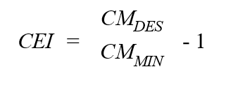
For metrics that decrease as efficiency increases, CEI shall be calculated as follows: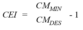
Where:
|
CMDES |
= |
Design cooling efficiency metric, part-load or annualized where available. |
|
CMMIN |
= |
Minimum required cooling efficiency metric, part-load or annualized where available from Section C403.3.2. |
For data centers using ASHRAE 90.4, CEI shall be calculated as follows: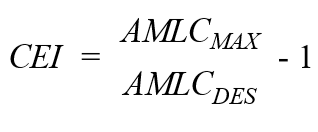
Where:
|
AMLCDES |
= |
As-designed annualized mechanical load component calculated in accordance with ASHRAE 90.4 Section 6.5. |
|
AMLCMAX |
= |
Maximum annualized mechanical load component from ASHRAE 90.4 Table 6.5. |
C406.2.2.2.3 Minimum fan efficiency. Where fan energy is not included in packaged equipment rating or it is and the fan size has been increased from the as-rated equipment condition, fan power or horsepower shall be less than 95 percent of the allowed fan power in Section C403.8.1.
C406.2.2.3 More efficient HVAC equipment heating performance. No less than 90 percent of the total HVAC capacity serving the total conditioned floor area of the entire building, building addition or tenant space in accordance with Section C406.1.1 shall comply with Sections C406.2.2.3.1 through C406.2.2.3.2.
C406.2.2.3.1 HVAC system selection. Equipment installed shall be types that are listed in the tables in Section C403.3.2. Electric resistance heating shall be limited to 20 percent of system capacity, with the exception of heat pump supplemental heating. No HVAC systems incorporating fossil fuel-fired equipment, or heat from district energy systems that are primarily heated by fossil fuel combustion, are permitted to utilize this credit unless the Section C401.3 fossil fuel compliance path is utilized for energy code compliance.
C406.2.2.3.2 Heating equipment efficiency. Equipment shall exceed the minimum heating efficiency requirements of the tables in Section C403.3.2 by at least 5 percent. Where equipment exceeds the minimum annual heating efficiency requirements by more than 5 percent, energy efficiency credits for heating shall be determined using Equation 4-16, rounded to the nearest whole number.
|
|
(Equation 4-16) |
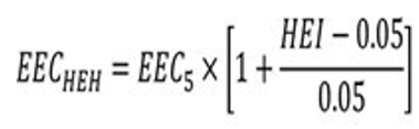
Where:
|
EECHEH |
= |
Energy efficiency credits for heating efficiency improvement. |
|
EEC5 |
= |
Section C406.2.2.2 credits from Table C406.2(1). |
|
HEI |
= |
The lesser of the improvement above minimum heating efficiency requirements or 20 percent (0.20). Where heating efficiency varies by system, use the capacity weighted average percentage for all heating equipment combined. For metrics that increase as efficiency increases, HEI shall be calculated as follows: |
|
|
|
|
Where:
|
HMDES |
= |
Design heating efficiency metric, part-load or annualized where available. |
|
HMMIN |
|
Minimum required heating efficiency metric, part-load or annualized where available from Section C403.3.2. |
EXCEPTION: In low energy spaces complying with Section C402.1.1 and semi-heated spaces complying with Section C402.1.1.2, no less than 90 percent of the installed heating capacity is provided by electric infrared or gas-fired radiant heating equipment for localized heating applications. Such spaces shall achieve credits for EEC5.
C406.2.2.4 Improved low-carbon district energy systems (10 percent better). Not less than 90 percent of the annual service hot water and space heating load, or not less than 90 percent of the annual service hot water, space heating, and space cooling load shall meet the criteria of Section C406.2.2.4.1 or C406.2.2.4.2.
Documentation for the low-carbon district system that is operational prior to the final inspection shall be provided to demonstrate that the definition as modified in Section C406.2.2.4.1 or C406.2.2.4.2 of low-carbon district energy exchange system is satisfied.
C406.2.2.4.1 Improved low-carbon district energy exchange systems (10 percent better). Low-carbon district energy exchange systems must demonstrate the following:
1. Forty-five percent of the annual district-system-net-load-met (sum of heating and cooling energy provided to attached buildings) comes from heat recovery between connected buildings, waste heat, or renewable energy resources; and
2. No more than 25 percent of the annual heat input to the system comes from fossil fuel or electric-resistance sources.
C406.2.2.4.2 Improved low-carbon district energy heating and cooling or heating only systems (10 percent better). Distribution losses must be accounted for and may not exceed 5 percent of the annual load delivered to buildings served by the system. Low-carbon district energy heating and cooling or heating only systems must demonstrate the following:
1. Forty-five percent of the annual district-system-net-load-met (sum of heating and cooling energy provided to attached buildings) comes from heat recovery between connected buildings, waste heat, or renewable energy resources and no more than 25 percent of the annual heat input to the system comes from fossil fuel or electric-resistance sources; or
2. No more than 10 percent of the system annual heat input to the system comes from fossil fuels or electric-resistance sources. The remaining annual heat input must be provided using heat pump technology with a minimum annual operating COP of 3.0.
C406.2.2.5 Improved low-carbon district energy systems (20 percent better). Not less than 90 percent of the annual service hot water and space heating load, or not less than 90 percent of the annual service hot water, space heating, and space cooling load shall meet the criteria of Section C406.2.2.5.1 or C406.2.2.5.2.
Documentation for the low-carbon district system that is operational prior to the final inspection shall be provided to demonstrate that the definition as modified in Section C406.2.2.4.1 or C406.2.2.4.2 of low-carbon district energy exchange system is satisfied.
C406.2.2.5.1 Improved low-carbon district energy exchange systems (20 percent better). Low-carbon district energy exchange systems must demonstrate the following:
1. Fifty percent of the annual district-system-net-load-met (sum of heating and cooling energy provided to attached buildings) comes from heat recovery between connected buildings, waste heat, or renewable energy resources; and
2. No more than 10 percent of the annual heat input to the system comes from fossil fuel or electric-resistance sources.
C406.2.2.5.2 Improved low-carbon district energy heating and cooling or heating only systems (20 percent better). Distribution losses must be accounted for and may not exceed 5 percent of the annual load delivered to buildings served by the system. Low-carbon district energy heating and cooling or heating only systems must demonstrate the following:
1. Fifty percent of the annual district-system-net-load-met (sum of heating and cooling energy provided to attached buildings) comes from heat recovery between connected buildings, waste heat, or renewable energy resources and no more than 10 percent of the annual heat input to the system comes from fossil fuel or electric-resistance sources; or
2. No more than 10 percent of the system annual heat input to the system comes from fossil fuels or electric-resistance sources. The remaining annual heat input must be provided using heat pump technology with a minimum annual operating COP of 4.0.
C406.2.2.6 High performance dedicated outdoor air system (DOAS). No less than 90 percent of the total conditioned floor area of the whole project, excluding floor area of unoccupied spaces that do not require ventilation as specified by the International Mechanical Code, shall be served by DOAS installed in accordance with Section C403.3.5 with the following adjustments:
1. Minimum heat recovery sensible effectiveness of 80 percent, calculated in accordance with Section C403.3.5.1, or C403.7.6.1 for R-2 occupancies.
2. Where design outdoor airflow is greater than 500 cfm (250 L/s), the DOAS shall be equipped with an economizer bypass, damper control, or wheel speed control that is active between 55°F (13°C) and 75°F (24°C) outdoor air temperature and minimizes energy recovery or maintains an appropriate DOAS leaving air temperature when the building is generally in cooling, based either on outdoor air temperature or a DDC zone-based cooling system reset.
3. DOAS total combined fan power shall comply with the fan power limits in Table C403.8.4 where applicable and shall be less than either:
3.1. 0.769 W/cfm (1.55 W/L/s) when calculated in accordance with Section C403.3.5.2.
3.2. Eighty percent of fan power allowance for a constant volume system when calculated in accordance with Section C403.8.1.
This option is not available to areas served by systems utilizing Section C403.2.2.1 Exception 5. No HVAC systems incorporating fossil fuel-fired equipment, or heat from district energy systems that are primarily heated by fossil fuel combustion, are permitted to utilize this credit unless the Section C401.3 fossil fuel compliance path is utilized for energy code compliance.
C406.2.2.7 Fault detection and diagnostics system. A project not required to comply with Section C403.2.3 or C403.6.10(16) shall achieve energy credits for installing a fault detection and diagnostics system to monitor the HVAC system’s performance and automatically identify faults. The installed system shall comply with items 1 through 6 in Section C403.2.3.
C406.2.3 Reduced lighting power. Interior lighting within the whole project, consisting of a whole building, building area, occupancy type, building addition, or tenant space, shall achieve credits by complying with Section C406.2.3.1 or C406.2.3.2. In Group R-1 and Group R-2 occupancies, dwelling and sleeping units shall comply with Section C406.2.3.3 and all other areas shall comply with section C406.2.3.1 or C406.2.3.2. Credits apply to the whole Group R-1 or Group R-2 area.
C406.2.3.1 Reduced lighting power option 1. The total connected interior lighting power calculated in accordance with Section C405.4.1 shall be 90 percent or less of the lighting power values specified in Table C405.4.2(1) times the floor area for the building types, or 90 percent or less of the total interior lighting power allowance calculated in accordance with Section C405.4.2.
C406.2.3.2 Reduced lighting power option 2. The total connected interior lighting power calculated in accordance with Section C405.4.1 shall be 80 percent or less of the lighting power values specified in Table C405.4.2(1) times the floor area of the building types, or 80 percent or less of the total interior lighting power allowance calculated in accordance with Section C405.4.2.
C406.2.3.3 Lamp efficacy. No less than 95 percent of the permanently installed light fixtures in dwelling units and sleeping units shall be provided by lamps with a minimum efficacy of 90 lumens per watt.
C406.2.4 Lighting controls. For buildings with nontransient dwelling units and sleeping units, energy credits shall be achieved by installation of systems that comply with the requirements of Section C406.2.4.1. All other buildings shall achieve energy credits by complying with Section C406.2.4.2. For buildings with mixed occupancies, credits shall be prorated based on floor area.
C406.2.4.1 Residential building lighting control. In buildings with nontransient dwelling units and sleeping units, lighting controls shall be configured to meet the following:
1. Each dwelling unit or sleeping unit shall have a main control by the main entrance that turns off all the lights and switched receptacles in the unit. The main control shall be permitted to have two controls, one for permanently wired lighting and one for switched receptacles. The main controls shall be clearly identified as “lights master off” and “switched outlets master off.”
2. Switched receptacles shall be clearly identified and all switched receptacles shall be located within 12 inches of an unswitched receptacle. Each room shall have a minimum of two switched receptacles except bathrooms, kitchens, and closets.
C406.2.4.2 Enhanced digital lighting controls. Measure credits shall be achieved where no less than 50 percent of the gross floor area within the project has luminaires and lighting controls that include high end trim in compliance with Section C405.2.8.3 and either luminaire-level lighting controls in compliance with Section C405.2.8.1 or networked lighting controls in accordance with Section C405.2.8.2. Open office areas subject to the requirements of Section C405.2.8 are not permitted to take credit for this option. Where general lighting in more than 50 percent of the gross floor area complies, the base credits from Table C406.2(1) shall be prorated as follows:
|
[Floor area with high end trim, %] × [Base energy credits for C406.2.4.2] / 50% |
C406.2.5 On-site and off-site renewable energy. Projects installing on-site or off-site renewable energy systems with a capacity of at least 0.1 watts per gross square foot (1.08 W/m2) of building area in addition to the renewable energy capacity required elsewhere in this code shall achieve energy credits for this measure. Renewable energy systems achieving energy credits shall not be used to satisfy other requirements of this code. Off-site renewable energy systems shall comply with Sections C411.2.2 and C411.2.3. Credits shall be prorated from the table value in accordance with Equation 4-17.
|
|
(Equation 4-17) |
Where:
|
AECRRa |
= |
Section C406.2.5 achieved energy credits for this project as calculated in accordance with Equation 4-17, limited to 50 percent of the required credits in Section C406.1. |
|
RRt |
= |
Actual total rating of on-site and off-site renewable energy systems (W) for each type of renewable energy source in Table C411.2.1. |
|
RRr |
= |
Rating of renewable energy systems required by Section C411.1, other sections in this code, or used to qualify for exceptions in this code (W). |
|
RRb |
= |
0.1 W/square foot (1.08 W/m2) |
|
PGFA |
= |
Project gross floor area, square feet (m2). |
|
AECb |
= |
Section C406.2.5 base credits from Table C406.2(1). |
|
REF |
= |
Renewable Energy Factor from Table C411.2.1. |
Informative Note: On-site renewable energy may include thermal service water heating or pool water heating, in which case ratings in Btu/h can be converted to W where W = Btu/h / 3.413.
C406.2.6 Reduced energy use in service water heating. Buildings with service hot water heating equipment that serves the whole building, building addition or tenant space shall achieve credits through compliance with:
1. Section C406.2.6.1, C406.2.6.2, or C406.2.6.3.
2. Sections C406.2.6.1 and C406.2.6.2.
3. Sections C406.2.6.1 and C406.2.6.3.
No service water heating systems incorporating fossil fuel-fired equipment, or heat from district energy systems that are primarily heated by fossil fuel combustion, are permitted to utilize this credit.
C406.2.6.1 Shower drain heat recovery. Shower drain heat recovery units shall comply with Section C404.10 and preheat cold water supply to the showers. Potable waterside pressure loss shall be less than 10 psi (69 kPa) at maximum design flow. The efficiency of drain water heat recovery units shall be no less than 54 percent in accordance with CSA B55.1. Full credits are applicable to the following building use types: Multi-family, hotel, motel, dormitory, and schools with locker room showers. Where not all showers in the project have drain heat recovery, the credit is adjusted based on the following:
|
[Section C406.2.6.1 table credits] × [Showers with drain recovery] / [Total number of showers] |
C406.2.6.2 Service water heating energy recovery. Not less than 30 percent of the annual service hot water heating energy use, or not less than 70 percent of the annual service hot water heating energy use in buildings with condenser water systems subject to the requirements of Section C403.9.2.1 or qualifying for one of its exceptions, shall be provided by one or more of the following:
1. Waste heat recovery from service hot water, heat recovery chillers, building equipment, process equipment, or other approved system. Qualifying heat recovery must be above and beyond heat recovery required by other sections of this code.
2. On-site renewable energy water-heating systems where not used to meet other requirements or to obtain other energy credits.
C406.2.6.3 Heat pump water heating. Projects shall achieve credits through compliance with Section C406.2.6.3.1.
C406.2.6.3.1 Heat pump water heater. Credit shall be achieved where the primary heat pump service water heating system is sized to deliver no less than 100 percent of the net calculated demand for service water production during the peak demand period with entering dry bulb or wet bulb outdoor air temperature at 40°F (4°C) for air-source heat pumps, or 44°F (7°C) ground temperature for ground-source heat pumps, as calculated using the equipment manufacturer’s selection criteria or another approved methodology. For this credit, the net calculated demand shall be the gross building demand less any portion of the demand complying with the exceptions to Section C404.2.1. Supplemental heating is permitted in accordance with Section C404.2.1, but cannot use fossil fuels. The refrigerant used in the heat pump system must have a global warming potential (GWP) no greater than 680. Heat pump water heaters shall comply with one of the following:
1. The COP rating shall be a minimum COP of 3.0 reported at the design leaving heat pump water temperature with an entering air temperature of 60°F (16°C) or lower. For water-source equipment, the COP rating will be reported at the design leaving load water temperature with an entering load water temperature of 74°F (23°C) or lower.
2. The uniform energy factor (UEF) shall be a minimum of 3.40 rated based on U.S. Department of Energy requirements.
C406.2.6.4 High efficiency service water heating, gas-fired. The credit achieved shall be from Table C406.2(2) where hot water is supplied by gas-fired equipment with minimum efficiency of 0.91 UEF.
C406.2.7 Improved service hot water temperature maintenance. For buildings with gross floor area greater than 10,000 square feet, credit shall be achieved when hot water temperature maintenance is installed in accordance with Section C406.2.7.1 or C406.2.7.2.
C406.2.7.1 Self-regulated heat trace system. The credit achieved shall be from Table C406.2(1). This system shall include self-regulating electric heat cables, connection kits and electronic controls. The cable shall be installed directly on the hot water supply pipes underneath the insulation to replace standby losses.
C406.2.7.2. Point of use water heater. The credit achieved shall be from Table C406.2(1) where any fixtures requiring hot water shall be supplied from a localized electric source of hot water with no recirculation or heat trace and limited to 2 kW and 6 gallons of storage. The supply pipe length from the point of use water heater to the termination of the fixture supply pipe shall be no more than 20 feet.
C406.2.8 Service hot water distribution right sizing. To achieve this credit, where Group occupancies are served by a central service hot water system, the distribution system serving dwelling units shall be sized using Appendix M of the Uniform Plumbing Code.
C406.2.9 High performance service hot water temperature maintenance system. Systems with multiple riser service hot water circulation systems shall use only heat pump technology for temperature maintenance. The heat pump technology shall have a minimum COP of 3.0 or UEF of 3.4. For air-source equipment, the COP rating will be reported at the design leaving heat pump water temperature with an entering dry bulb air temperature of 60°F (16°C) or lower and a relative humidity of 50 percent or lower. For water-source equipment, the COP rating will be reported at the design leaving load side water temperature with an entering source side water temperature of 74°F (23°C) or lower. The system shall comply with the requirements of Section C404.7.1.
C406.2.10 High efficiency service hot water circulation system. Multiple riser service hot water circulation systems shall use a variable volume circulation pump controlled to vary the pump speed based on system demand and shall include self-actuated thermostatic balancing valves to control the system flow at each riser.
C406.2.11 Low flow showerheads for Group R-1 and R-2 occupancies. All showerheads installed in Group R-1 and R-2 dwelling units or sleeping units shall have a maximum listed flowrate of 1.25 gallons per minute or less at 80 psi operating pressure for fixed showerheads and a maximum listed flowrate of 1.50 gallons per minute or less at 80 psi operating pressure for handheld showerheads. When a shower is served by more than one showerhead, including handheld showerheads, the combined flow rate of all showerheads and/or other shower outlets controlled by a single valve shall not exceed 1.25 gallons per minute or less for fixed or 1.5 gallons per minute or less for handheld, or the shower shall be designed to allow only one shower outlet to be in operation at a time.
C406.2.12 Enhanced envelope performance. The Proposed Total UA of the thermal envelope of the project shall be 15 percent lower than the Allowable Total UA determined in accordance with Section C402.1.5 and Equation 4-2.
C406.2.13 Reduced air leakage. Energy credits shall be achieved where measured air leakage of the total conditioned floor area of the whole building, fully isolated building addition or tenant space is determined in accordance with Section C402.5.1.2 and complies with the maximum leakage in either Section C406.2.13.1 or C406.2.13.2.
C406.2.13.1 Base reduced air leakage. Measured air leakage shall not exceed 68 percent of the maximum leakage allowed by Section C402.5.1.2.
C406.2.13.2 Enhanced reduced air leakage. Measured air leakage shall not exceed 33 percent of the maximum leakage allowed by Section C402.5.1.2.
C406.2.15 Residential kitchen equipment. For projects with Group R-1 and R-2 occupancies, energy credits shall be achieved where not less than 90 percent of dishwashers, refrigerators, and freezers comply with all of the following:
1. Achieve the ENERGY STAR Most Efficient label in accordance with the 2021 specifications.
2. Be installed prior to the issuance of the certificate of occupancy.
For Group R-1 where only some guestrooms are equipped with both refrigerators and dishwashers, the table credits shall be prorated as follows:
|
[Section C406.2.15 table credits] × [Floor area of guestrooms with kitchens] / [Total guestroom floor area] |
C406.2.16 Residential laundry appliances. For projects with Group R-2 occupancies, energy credits shall be achieved where not less than 90 percent of clothes washers and dryers in the project meet the following requirements:
1. Each dwelling unit contains in-unit washing washer and dryer equipment that meets the following requirements:
1.1. Achieve the ENERGY STAR Most Efficient label in accordance with the 2021 specifications.
1.2. Be installed prior to the issuance of the certificate of occupancy.
2. Where only some dwelling units are equipped with both washers and dryers, the table credits shall be prorated as follows:
|
[Section C406.2.16 table credits] × [Floor area of dwelling units with laundry] / [Total dwelling unit floor area] |
C406.2.17 Heat pump clothes dryers. Not less than 90 percent of domestic clothes dryers located in Group R-1 and R-2 of the whole project are ENERGY STAR rated heat pump dryers. Credit applies only to buildings where laundry facilities are provided either within each residential dwelling or sleeping units or grouped together in central multi-family use laundry rooms, or a mix of the two.
To claim this credit, the building permit drawings shall specify the appliance type and provide documentation of ENERGY STAR compliance. At the time of inspection, all appliances shall be installed and connected to utilities.
C406.2.18 Efficient elevator equipment. Qualifying elevators in the building shall be Energy Efficient Class A in accordance with ISO 25745-2, Table 7. Only buildings three or more floors above grade shall be permitted to use this credit. Credits shall be prorated based on Equation 4-18, rounded to the nearest whole credit. Projects with a compliance ratio (CRe in Equation 4-18) below 0.5 do not qualify for this credit.
|
|
(Equation 4-18) |
Where:
|
ECe |
= |
Elevator energy credit achieved for building. |
|
ECt |
= |
Section C406.2.18 table energy credit. |
|
CRe |
= |
|
|
FA |
= |
Sum of floors served by Class A elevators. |
|
FB |
= |
Sum of floors served by all building elevators and escalators. |
C406.3 Load management credits. Load management measures installed in the building that meet the requirements in Sections C406.3.1 through C406.3.7 shall achieve the credits listed for the occupancy group in Table C406.3 or where calculations required by Sections C406.3.1 through C406.3.7 create or modify the table credits the credits achieved will be based upon the section calculations.
Each load management measure shall require automatic controls activated by either utility demand response, utility price response signal, peak price period time control, or local building demand monitoring. Controls shall be capable of and configured to provide the required load management sequences. As used in this section, “peak period” shall be either the coincident peak building load period, the peak price period, the peak utility load period, or the peak building demand period. The following additional requirements apply to these measures:
1. Where credit is taken for C406.3.6, service water heating energy storage, the equipment shall be provided with controls that comply with ANSI/CTA 2045-B.
2. For load management measures in Sections C406.3.1 through C406.3.5:
2.1. Where the serving utility has a real-time demand response or pricing program, an interface compliant with serving utility requirements shall be installed.
2.2. Where the serving utility does not have a real-time demand response or pricing program, a digital input to the system to support future utility programs shall be installed and building demand monitoring shall be installed and integrated into the load management sequence.
2.3. All equipment involved in the required load management sequence shall have controls connected to a central DDC system.
|
Measure Title |
Applicable Section |
Occupancy Group |
|||||
|---|---|---|---|---|---|---|---|
|
Group R-1 |
Group R-2 |
Group B |
Group E |
Group M |
All Other |
||
|
1. Lighting load management |
C406.3.1 |
12 |
15 |
27 |
15 |
NA |
NA |
|
2. HVAC load management |
C406.3.2 |
29 |
24 |
42 |
23 |
13 |
26 |
|
3. Automated shading |
C406.3.3 |
NA |
7 |
12 |
16 |
NA |
NA |
|
4. Electric energy storage |
C406.3.4 |
41 |
50 |
126 |
72 |
37 |
65 |
|
5. Cooling energy storage |
C406.3.5 |
13 |
10 |
14 |
19 |
NA |
14 |
|
6. Service hot water energy storage |
C406.3.6 |
31 |
248 |
59 |
8 |
5 |
70 |
|
7. Building thermal mass |
C406.3.7 |
NA |
NA |
50 |
95 |
96 |
80 |
C406.3.1 Lighting load management. Automatic controls shall be capable of gradually reducing general lighting power with continuous dimming in 75 percent of the building area by at least 20 percent during peak demand periods. Where less than 75 percent, but at least 50 percent, of the building area lighting is controlled, the credits from Table C406.3 shall be prorated as follows:
|
[Area of building with lighting load management, %] × [Table credits for C406.3.1] 75% |
EXCEPTION: Warehouse or retail storage building areas shall be permitted to achieve this credit by switching off at least 25 percent of lighting power in 75 percent of the building area without dimming.
C406.3.2 HVAC load management. Automatic controls shall:
1. Where electric cooling is used, be configured to gradually increase, over a minimum of three hours, the cooling setpoint by at least 3°F during the summer peak periods.
2. Where electric heating is used, be configured to gradually reduce, over a minimum of three hours, the heating setpoint by at least 3°F during winter peak periods.
C406.3.3 Automated shading load management. Where fenestration on south and west exposures exceeds 20 percent of the wall area, automatic controls shall be configured to operate movable exterior shading devices or dynamic glazing to reduce solar gain through sunlit fenestration on southern and western exposures by at least 50 percent during summer peak periods.
Informative Note: This credit can be met by exterior roller, movable blind or movable shutter shading devices; however, fixed overhang, screen or shutter shading will not meet the requirement. Roller shades that reject solar gain but still allow a view are allowed as long as they provide an effective 50 percent reduction in net solar gain (e.g., have a shading coefficient of less than 0.5 for the shading material itself). Interior shading devices will not meet the requirement. Electrochromatic windows that achieve 50 percent of SHGC would qualify.
C406.3.4 Electric energy storage. Automatic controls shall store electricity in electric storage devices during nonpeak periods and use stored energy during peak periods. Electric storage devices shall have a minimum capacity of 5 Wh/ft2 (58 Wh/m2) of gross building area. For greater storage capacity up to 15 Wh/ft2 (160 Wh/m2), credits shall be prorated as follows:
|
[Installed electric storage capacity, Wh/ft2]/5 × [C406.3.4 credits from Table C406.3] |
C406.3.5 Cooling energy storage. Automatic controls shall be capable of activating ice or chilled water storage to reduce peak period electric demand. Credits shown in Table C406.3 are based on storage capacity of 2 ton-hours per design day ton of cooling load (2 kWh per design day kW) with a 1.15 sizing factor. Credits shall be prorated for installed storage systems sized between 0.5 and 3.5 ton-hours per design day ton (kWh per design day kW) of cooling load rounded to the nearest whole credit. The storage tank shall have no more than 1.5 percent of storage capacity standby loss per day.
C406.3.6 Service hot water energy storage. To achieve this credit, where service hot water is heated by electricity, automatic controls shall preheat stored service hot water before the peak period and suspend electric water heating during the peak period. Storage capacity shall be provided by either:
1. Preheating water above 140°F (60°C) delivery temperature with at least 1.34 kWh of energy storage per kW of water heating capacity. Tempering valves shall be provided at the water heater delivery location.
2. Providing additional heated water tank storage capacity above peak service hot water demand with equivalent peak storage capacity to item 1.
C406.3.7 Building thermal mass. To achieve this credit, the building shall have both additional passive interior mass and a night-flush control of the HVAC system.
1. Interior to the building thermal envelope insulation, provide 15 pounds of passive thermal mass per square foot of building floor area. Mass construction shall be in the building interior and the indoor facing portion of the exterior wall, and interior floor construction. Mass construction shall have mass surfaces in direct contact with the air in conditioned spaces with directly attached wall board or hard surface flooring allowed. Mass with carpet or furred wallboard shall not be counted toward the building mass required. For integral insulated concrete block walls complying with ASTM C90, only the mass of the interior face shall be counted toward the building mass required.
2. When summer mode is active and indoor average temperature is 5°F (3°C) or more above outdoor temperature and between 10:00 p.m. and 6:00 a.m., automatic night flush controls shall operate outdoor air economizers at low fan speed less than 66 percent during the unoccupied period until the average indoor air temperature falls to the occupied heating setpoint. Summer mode shall be activated when outdoor air exceeds 70°F (21°C) and continues until deactivated when outdoor air falls below 45°F (7°C). Another night flush strategy shall be permitted where demonstrated to be effective, avoids added morning heating and is approved by the code official.
Informative Note: The simplified night flush sequence described will operate in “summer mode” below the 70°F outdoor air trigger temperature down until outdoor air of 45°F is hit when the “summer mode” is deactivated until the outdoor air temperature rises above 70°F again. Other strategies may be implemented that cool the space below the heating setpoint and adjust the morning heating setpoint to avoid morning reheating.
SECTION C407 TOTAL BUILDING PERFORMANCE
C407.1 Scope. This section establishes criteria for compliance using total building performance. All systems and loads shall be included in determining the total building performance including, but not limited to: Heating systems, cooling systems, service water heating, fan systems, lighting power, receptacle loads and process loads.
EXCEPTION: Energy used to recharge or refuel vehicles that are used for on-road and off-site transportation purposes.
C407.2 Mandatory requirements. Compliance with Section C407 also requires compliance with those sections shown in Table C407.2.
The building permit application for projects utilizing this method shall include in one submittal all building and mechanical drawings and all information necessary to verify that the building envelope and mechanical design for the project corresponds with the annual energy analysis. If credit is proposed to be taken for lighting energy savings, then an electrical permit application shall also be submitted and approved prior to the start of building construction. If credit is proposed to be taken for energy savings from other components, then the corresponding permit application (e.g., plumbing, boiler, etc.) shall also be submitted and approved prior to the building permit application. Otherwise, components of the project that would not be approved as part of a building permit application shall be modeled in the baseline in accordance with ANSI/ASHRAE/IESNA 90.1 Appendix G and in the proposed model in accordance with the requirements of the Shoreline Energy Code.
|
Sectiona |
Title |
Comments |
|---|---|---|
|
Envelope |
||
|
C401.4 |
Thermal envelope certificate |
|
|
C402.2.7 |
Airspaces |
|
|
C402.5 |
Air leakage |
|
|
Mechanical |
||
|
C403.1.2 |
Calculation of heating and cooling loads |
|
|
C403.1.3 |
Data centers |
|
|
C403.2 |
System design |
|
|
C403.3.1 |
Equipment and system sizing |
|
|
C403.3.2 |
HVAC equipment performance requirements |
|
|
C403.3.3 |
Hot gas bypass limitation |
|
|
C403.3.4.4 |
Boiler turndown |
|
|
C403.4.1 |
Thermostatic controls |
|
|
C403.4.2 |
Off-hour controls |
|
|
C403.4.7 |
Combustion heating equipment controls |
|
|
C403.4.8 |
Group R-1 hotel/motel guestrooms |
See Section C403.7.4 |
|
C403.4.9 |
Group R-2 and R-3 dwelling units |
|
|
C403.4.10 |
Group R-2 sleeping units |
|
|
C403.4.11 |
Direct digital control systems |
|
|
C403.5.5 |
Economizer fault detection and diagnostics (FDD) |
|
|
C403.7 |
Ventilation and exhaust systems |
Except for C403.7.6.2 |
|
C403.8 |
Fan and fan controls |
|
|
C403.9.1.1 |
Variable flow controls |
For cooling tower fans ≥ 7.5 hp |
|
C403.9.1.3 |
Limitation on centrifugal fan cooling towers |
For open cooling towers |
|
C403.10 |
Construction of HVAC elements |
|
|
C403.11 |
Mechanical systems located outside of the building thermal envelope |
|
|
C403.14 |
Commissioning |
|
|
Service Water Heating |
||
|
C404 |
Service water heating |
Except for C404.2.1 |
|
Lighting and Electrical |
||
|
C405 |
Electrical power and lighting systems |
|
|
Other Requirements |
||
|
C407 |
Total building performance |
|
|
C408 |
System commissioning |
|
|
C409 |
Energy metering |
|
|
C410 |
Refrigeration requirements |
|
|
C411b |
Renewable energy |
|
|
C412 |
Compressed air systems |
|
a Reference to a code section includes all the relative subsections except as indicated in the table.
b Compliance with any of these sections includes compliance with any exception to that section.
C407.3 Performance-based compliance. Compliance with this section requires compliance with ASHRAE Standard 90.1 Appendix G, Performance Rating Method, in accordance with Standard 90.1 Section 4.2.1 with the following modifications:
1. The mandatory requirements of the Shoreline Energy Code are required to be met, instead of those of Section G1.2.1a of ANSI/ASHRAE/IESNA 90.1
2. Compliance with Section C407 requires meeting both a regulated site energy target and a total site energy reduction target in accordance with the following:
2.1. Regulated site energy target. The regulated site energy target is focused on regulated load energy efficiency, thus shall be met only via regulated load savings without consideration of the contribution of on-site or off-site renewable energy or unregulated load savings. Adjustments to the PCI, to account for the contribution of renewable energy found in ANSI/ASHRAE/IESNA 90.1 Section 4.2.1.1 shall not be used. References to energy cost in Section 4.2.1.1 and Appendix G shall be replaced by site energy use. Heating or cooling energy provided by a district energy system may utilize coefficient of performance (COP) ratios acceptable to the code official for the respective district energy sources. The building performance factors in Table 4.2.1.1 of ANSI/ASHRAE/IESNA 90.1 shall be replaced with those in Table C407.3(2).
2.2. Total site energy target. The total site energy performance target shall be met including the contributions of on-site or off-site renewable energy as described in Section C411.2 as well as the contributions of improvements in unregulated loads as allowed by Section C407.3.4. The annual on-site and off-site renewable energy production (as adjusted by the factors in Table C411.2.1) shall be subtracted from the proposed building annual site energy use. Compliance with the site energy performance target requires that the proposed building site energy use/baseline building site energy use is less than or equal to the site energy performance target from Table C407.3(3).
3. Documentation requirements in Section G1.3.2.d shall be replaced by a list showing compliance with the mandatory provisions of Table C407.2.
4. Forms demonstrating compliance with Appendix G developed by the U.S. Department of Energy shall be completed and submitted to the code official. The forms are available at energycodes.gov/ashrae-standard-901-performance-based-compliance-form.
5. References to yet-to-be-designed future building components in the Proposed Building Performance column of Table G3.1 shall be modified to reference the corresponding sections of the Shoreline Energy Code in lieu of the requirements of ANSI/ASHRAE/IESNA 90.1 in the following sections of the table:
5.1. No. 1, Design Model, subclause c.
5.2. No. 6, Lighting, subclause c.
5.3. No. 11, Service Water Heating System, subclause c.
5.4. No. 12, Receptacle and Other Loads, subclause b.
6. HVAC systems, subclauses c and d of Table G3.1, shall meet the following requirements:
6.1. For yet-to-be-designed systems in office, retail, library, education, and multifamily buildings and occupancies subject to the TSPR requirements of Section C403.1.1, the system type and efficiency parameters in the proposed model shall meet but not exceed those shown in Table D602.11 Standard Reference Design HVAC Systems.
6.2. For all other buildings and occupancies, the system type shall be the same as the system modeled in the baseline design and shall comply with but not exceed the requirements of Section C403 in lieu of ANSI/ASHRAE/IESNA 90.1.
6.3. For HVAC systems serving future tenant spaces, where the current building permit applies to only a portion of an HVAC system, and future components will receive HVAC services from systems included in the current building permit, those future components shall be modeled as the type required to complete the HVAC system portions under the current permit and shall meet but not exceed the requirements found in Section C403.
7. The requirements for proposed and baseline building lighting system shall be modified in accordance with Addendum af to ANSI/ASHRAE/IESNA 90.1.
8. Energy modeler qualifications. The energy analyst in responsible charge of the Section C407 submittal shall meet at least one of the following:
8.1. ASHRAE Building Energy Modeling Professional (BEMP) certification.
8.2. Association of Energy Engineer’s Building Energy Simulation Analyst (BESA) certification.
8.3. Successful completion of at least five projects modeled following any version of ANSI/ASHRAE/IESNA 90.1 Appendix G within the last three years that were reviewed and approved by a code official or rating authority.
|
Building Area Type |
Building Performance Factor |
|---|---|
|
Multifamily |
0.45 |
|
Health care/hospital |
0.70 |
|
Hotel/motel |
0.46 |
|
Office |
0.44 |
|
Restaurant |
0.33 |
|
Retail |
0.41 |
|
School |
0.35 |
|
Warehouse |
0.18 |
|
All others |
0.43 |
|
Building Area Type |
Site Energy Performance Targets |
|---|---|
|
Multifamily |
0.53 |
|
Health care/hospital |
0.72 |
|
Hotel/motel |
0.56 |
|
Office |
0.58 |
|
Restaurant |
0.59 |
|
Retail |
0.46 |
|
School |
0.52 |
|
Warehouse |
0.29 |
|
All others |
0.55 |
C407.3.1 Limits on substandard building envelopes. The Proposed Total UA of the proposed building shall be no more than 10 percent higher than the Allowed Total UA as defined in Section C402.1.5.
C407.3.2 On-site and off-site renewable energy accounting for use with Appendix G. Qualifying on-site and off-site renewable energy delivered or credited to the building project to comply with Section C407.3 item 2.2 shall meet the requirements of Section C411.2.
C407.3.3 Low-carbon district energy use with Appendix G. Qualifying low-carbon district heating and cooling or heating only systems and low-carbon district energy exchange systems shall meet the requirements of Section C407.3.3.1 or C407.3.3.2, as applicable.
C407.3.3.1 Utilization of low-carbon district heating and cooling or heating only systems. Applicable if heating and cooling or heating only is provided to the proposed building from a low-carbon district heating and cooling or heating only system that is fully operational prior to the final inspection. Proposed model shall account for all on-site HVAC and service hot water related equipment, such as circulation pump energy and heat-exchanger efficiency.
1. The following modifications shall be applied to Appendix G of ANSI/ASHRAE/IESNA 90.1 in addition to what is described in Section C407.3:
1.1. For low-carbon district heating and cooling systems, strike the text of Sections G3.1.1.1, G3.1.1.2, G3.1.1.3.1, G3.1.1.3.3, and G3.1.1.3.4. Baseline system shall be selected based on unmodified versions of Tables G3.1.1-3 and G3.1.1-4, comparing energy use to determine compliance.
1.2. For low-carbon district heating only systems, strike the text of Sections G3.1.1.1, G3.1.1.3.1, and G3.1.1.3.4. Baseline system shall be selected based on unmodified versions of Tables G3.1.1-3 and G3.1.1-4, comparing energy use to determine compliance.
2. Any heating or cooling energy provided by the low-carbon district heating and cooling or heating only system shall utilize a calculated energy use reduction factor acceptable to the code official to account for energy use reduction from those end uses.
3. Energy “credit” for any waste/recoverable heat exported to the low-carbon district heating and cooling or heating only systems shall be accounted for in the proposed design by multiplying the quantity of heat exported by the appropriate seasonal utilization factor in Items 3.1 and 3.2 below. This energy “credit” is subtracted from the total proposed design energy use calculated in accordance with ASHRAE 90.1 Section 4.2.1.1.
3.1. Fifty percent of the waste heat exported to the low-carbon district heating and cooling or heating only systems during the months of October through December and January through March.
3.2. Twenty-five percent of the waste heat exported to the low-carbon district heating and cooling or heating only systems during the months of April through September.
EXCEPTION: Waste heat exported from the building to the low-carbon district heating and cooling or heating only system shall not be subtracted from the proposed design energy use if they are already accounted for in the calculation of energy use from the district heating or cooling plant as part of the district energy efficiency factor.
Documentation for the low-carbon district system that is operational prior to the final inspection shall be provided to demonstrate the following:
1. Distribution losses must be accounted for and may not exceed 10 percent of the annual load delivered to buildings served by the system.
2. Twenty-five percent of the annual district-system-net-load-met (sum of heating and cooling energy provided to attached buildings) comes from heat recovery between connected buildings, waste heat or renewable energy resources and no more than 25 percent of the annual heat input to the system comes from fossil fuel or electric-resistance sources, or not more than 10 percent of the system annual heat input to the system comes from fossil fuel or electric-resistance sources.
C407.3.3.2 Utilization of low-carbon district energy exchange systems. Applicable if heating or cooling is provided to the proposed building from a low-carbon district energy exchange system that is fully operational prior to the final inspection. Proposed model shall account for all on-site HVAC and service hot water related equipment, such as circulation pump energy and heat-exchanger efficiency.
1. The following modifications shall be applied to Appendix G of ANSI/ASHRAE/IESNA 90.1 in addition to what is described in Section C407.3:
1.1. Strike the text of Sections G3.1.1.1, G3.1.1.2, G3.1.1.3, G3.1.1.3.1, G3.1.1.3.2, G3.1.1.3.3, and G3.1.1.3.4. Baseline system shall be selected based on unmodified versions of Tables G3.1.1-3 and G3.1.1-4.
2. Any heating or cooling energy provided by a low-carbon district energy exchange system shall utilize a calculated energy use reduction factor acceptable to the code official to account for the reduction in the proposed model.
3. Energy use “credit” for any waste/recoverable heating exported to the low-carbon district energy exchange system shall be accounted for in the proposed design by multiplying the quantity of heat exported by the appropriate seasonal utilization factor in Items 3.1 and 3.2 below. This energy use “credit” is subtracted from the total proposed design energy use calculated in accordance with ASHRAE 90.1 Section 4.2.1.1.
3.1. Fifty percent of the waste heat exported to the low-carbon district energy exchange system during the months of October through December and January through March.
3.2. Twenty-five percent of the waste heat exported to the low-carbon district energy exchange system during the months of April through September.
EXCEPTION: Waste heat exported from the building to the low-carbon district heating and cooling or heating only system shall not be subtracted from the proposed design energy use if they are already accounted for in the calculation of energy use from the district heating or cooling plant as part of the district energy efficiency factor.
Documentation for the low-carbon district system that is operational prior to the final inspection shall be provided to demonstrate that the definition of low-carbon district energy exchange system is satisfied.
C407.3.4 Credit for improvements in unregulated loads when using Appendix G. When calculating savings for site energy targets in accordance with Section C407.3 item 2.2, but not when calculating savings for site energy targets in accordance with Section C407.3 item 2.1, differences in the simulation of unregulated loads and equipment modeled in the baseline building design from those in the proposed design shall be approved by the code official based on documentation that the equipment installed in the proposed design represents a significant verifiable departure from documented current conventional practice. All unregulated equipment for which savings is claimed must be installed by the time of final inspection. The burden of this documentation is to demonstrate that accepted conventional practice would result in baseline building equipment different from that installed in the proposed design. Occupancy and occupancy schedules shall not be changed.
C407.3.4.1 Approved unregulated load types. Unregulated load types for which reductions of energy use are claimed shall be one of those listed in Table C407.3.4.1 or shall be approved and publicly listed by the Building Official. Requests for approval of such load types shall include the identification with predicted energy use of the baseline case in addition to the identification with predicted energy use of the proposed alternate. Listings for specific load types may be withdrawn and made unavailable for subsequent permit applications in cases by the Building Official where it is considered that the unregulated load type listed has become accepted conventional practice. Unregulated load savings shall follow the methodology outlined in this section, and not use the language from Appendix G Table G3.1 - No. 12 Receptacle and Other Load Baseline Building Performance Exception.
|
In compliance with the requirements of section |
Predicted energy reductions (%) |
|
|---|---|---|
|
Group R-1 |
Group R-2 |
|
|
C406.2.15, Enhanced residential kitchen equipment |
1.2 |
1.9 |
|
C406.2.16, Enhanced residential laundry equipment |
N/A |
0.6 |
|
C406.2.17, Heat pump clothes dryers |
0.6 |
0.6 |
SECTION C408 SYSTEM COMMISSIONING
C408.1 General. A building commissioning process led by a certified commissioning professional and functional testing requirements shall be completed for mechanical systems in Section C403; service water heating systems in Section C404; controlled receptacle and lighting control systems in Section C405; equipment, appliances and systems installed to comply with Sections C406 or C407; energy metering in Section C409; and refrigeration systems in Section C410.
EXCEPTION: Buildings, or portions thereof, which are exempt from Sections C408.2 through C408.7 may be excluded from the commissioning process.
1. Mechanical systems that are not required to comply with Section C403.3.5 are exempt from the commissioning process where the installed total mechanical equipment capacity is less than 180,000 Btu/h (15 tons) cooling capacity and less than 240,000 Btu/h (20 tons) heating capacity and energy recovery ventilation (ERV) equipment is less than 300 cfm capacity.
2. Service water heating systems are exempt from the commissioning process in buildings where the largest service water heating system capacity is less than 200,000 Btu/h and where there are none of the following:
2.1. pools or permanent spas.
2.2. solar thermal water heating.
2.3. recirculation pumps.
2.4. heat pump water heaters, except fully-packaged for individual residential dwelling unit use.
3. Lighting control systems are exempt from the commissioning process in buildings where both the total installed lighting load is less than 10 kW and the lighting load controlled by occupancy sensors or automatic daylighting controls is less than 5 kW.
4. Refrigeration systems are exempt from the commissioning process in buildings if they are limited to self-contained units.
C408.1.1 Commissioning in construction documents. Construction documents shall clearly indicate provisions for commissioning process. Electrical permit documents shall indicate required commissioning work for lighting and metering systems, and mechanical permit documents shall indicate required commissioning work for mechanical and water heating systems. The construction documents shall minimally include the following:
1. A narrative description of the activities that will be accomplished during the commissioning process. At a minimum, the commissioning process is required to include:
1.1. Development and execution of the commissioning plan, including all subsections of Section C408.1.2;
1.2. The certified commissioning professional’s review of the building documentation and close out submittals in accordance with Section C103.6; and
1.3. The commissioning report in accordance with Section C408.1.3.
2. Roles, responsibilities, and required qualifications of the certified commissioning professional.
3. A listing of the specific equipment, appliances, or systems to be tested.
C408.1.2 Commissioning plan. A commissioning plan shall be developed by the project’s certified commissioning professional, shall be submitted to the Building Official prior to the first mechanical inspection, and shall outline the organization, schedule, allocation of resources, and documentation requirements of the commissioning process.
1. A narrative description of the activities that will be accomplished during each phase of commissioning, including the personnel intended to accomplish each of the activities, systems testing and balancing, functional performance testing, and verification of the building documentation requirements in Section C103.6.
2. Roles and responsibilities of the commissioning team, including the name and statement of qualifications of the certified commissioning professional.
3. A listing of the specific equipment, appliances or systems to be tested and a description of the tests to be performed.
C408.1.2.1 In-house commissioning disclosure and conflict management plan. Where the certified commissioning professional’s contract or employment is other than directly with the building owner, an in-house commissioning disclosure and conflict management plan shall be a part of the commissioning process. A copy shall be included in the commissioning plan. This plan shall disclose the certified commissioning professional’s contractual relationship with other team members and provide a conflict management plan demonstrating that the certified commissioning professional is free to identify any issues discovered and report directly to the owner.
C408.1.2.2 Functional performance testing. Functional performance testing shall be conducted for mechanical systems in Sections C403; service water heating systems in Section C404; controlled receptacles and lighting control systems in Section C405; equipment, appliances, systems installed to comply with Section C406 or C407; energy metering in Section C409; and refrigeration systems in Section C410. Written procedures which clearly describe the individual systematic test procedures, the expected system response or acceptance criteria for each procedure, the actual response or findings, and any pertinent discussion shall be followed. This testing shall include control systems which will be tested to document that control devices, components, equipment, and systems are calibrated and adjusted to operate in accordance with approved construction documents. Testing shall affirm the conditions required within Sections C408.2 through C408.7 under system testing.
C408.1.2.3 Functional performance testing - Sampling. For projects with 7 or fewer similar systems, each system shall be tested. For projects with more than 7 systems, testing shall be done for each unique combination of control types. Where multiples of each unique combination of control types exist, no fewer than 20 percent of each combination shall be tested unless the code official or design professional requires a higher percentage to be tested. Where 30 percent or more of the tested system fail, all remaining identical combinations shall be tested.
C408.1.2.4 Deficiencies. Deficiencies found during testing shall be resolved including corrections and retesting.
C408.1.3 Commissioning report. A commissioning report shall be completed and certified by the certified commissioning professional and delivered to the building owner or owner’s authorized agent. The report shall be organized with mechanical, service water heating, controlled receptacle and lighting control systems, energy metering, and refrigeration findings in separate sections to allow independent review. The report shall record the activities and results of the commissioning process and be developed from the final commissioning plan with all of its attached appendices. The report shall be submitted to building official prior to the final inspection and shall include:
1. Results of functional performance tests.
2. Disposition of deficiencies found during testing, including details of corrective measures used or proposed.
3. Functional performance test procedures used during the commissioning process including measurable criteria for test acceptance, provided herein for repeatability.
4. Commissioning plan.
5. Testing, adjusting and balancing report.
EXCEPTION: Deferred tests which cannot be performed at the time of report preparation due to climatic conditions.
C408.1.4 Commissioning process completion requirements. Prior to the final mechanical, plumbing and electrical inspections or obtaining a certificate of occupancy, the certified commissioning professional shall provide evidence of building commissioning in accordance with the provisions of this section.
C408.1.4.1 Commissioning compliance. The mechanical and water portions of the commissioning report in compliance with Sections C408.2, C408.3, and C408.7, shall be submitted to the building official prior to completion and approval of mechanical permit final inspection. Metering portions of the commissioning report, in compliance with Sections C408.4 and C408.6, shall be submitted to the building official prior to completion and approval of electrical permit final inspection. The controlled receptacle, lighting and metering portions of the commissioning report, in compliance with Sections C408.4 and C408.6 shall be submitted to the building official prior to completion and approval of electrical permit final inspection.
The following items shall be submitted to the building official prior to completion and approval of final inspection to demonstrate commissioning compliance:
1. Full commissioning report, in compliance with Section C408.1.3.
a. The commissioning report shall include a list of all unresolved deficiencies and any incomplete commissioning work required by Section C408, with description and anticipated date of completion for each, or a statement signed by the certified commissioning professional attesting to successful commissioning of the entire project with no unresolved deficiencies or incomplete tests.
b. Where tenant spaces will be built out under separate permits, the commissioning report shall describe the certified commissioning professional’s scope of work required to complete commissioning of the central building HVAC systems and lighting control systems as the tenant spaces are completed.
2. Commissioning checklist, from Figure C408.1.4.1, signed by the certified commissioning professional.
3. Statement that the owner has received a copy of the commissioning report, signed by the owner or owner’s authorized agent.
C408.1.4.1.1 Post-occupancy commissioning completion. Where there are unresolved deficiencies or other incomplete commissioning tasks that conflict with requirements of this code, the applicant shall comply with the requirements of one of the following three options.
1. In addition to the Temporary Certificate of Occupancy requirements of SBC 109.4, the Building Official may issue a temporary certificate of occupancy (TCO) to remain in effect pending resolution of commissioning issues. Applicant must complete all outstanding commissioning work and complete a revised commissioning report before the Building Official will issue a final Certificate of Occupancy.
2. Applicant must post a performance bond in the amount of 2 percent of the building permit project valuation as determined in accordance with the fee subtitle, to ensure completion of the required commissioning work within 12 months.
3. Applicant must obtain electrical and mechanical permits as required to incorporate all remaining electrical and mechanical work, including required commissioning of those systems. Applicant must complete all outstanding electrical and mechanical commissioning work and complete a revised commissioning report prior to completion and approval of final inspection for those permits.
C408.2 Mechanical systems commissioning. Mechanical equipment and controls subject to Section C403 shall be included in the commissioning process required by Section C408.1. The commissioning process shall minimally include all energy code requirements for which the code states that equipment or controls shall “be capable of” or “configured to” perform specific functions.
Exception: Mechanical systems are exempt from the commissioning process where the installed total mechanical equipment capacity is less than 180,000 Btu/h cooling capacity and less than 240,000 Btu/h heating capacity, and energy recovery ventilation (ERV) equipment is less than 300 cfm capacity.
C408.2.1 Reserved.
FIGURE C408.1.4.1
COMMISSIONING COMPLIANCE CHECKLIST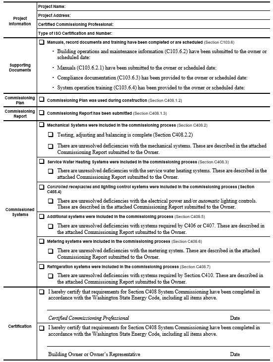
C408.2.2 Systems adjusting and balancing. HVAC systems shall be balanced in accordance with generally accepted engineering standards. Air and water flow rates shall be measured and adjusted to deliver final flow rates within the tolerances provided in the project specifications. Test and balance activities shall include air system and hydronic system balancing.
C408.2.2.1 Air systems balancing. Each supply air outlet and zone terminal device shall be equipped with means for air balancing in accordance with the requirements of Chapter 6 of the International Mechanical Code. Discharge dampers used for air system balancing are prohibited on constant volume fans and variable volume fans with motors 10 hp (18.6 kW) and larger. Air systems shall be balanced in a manner to first minimize throttling losses then, for fans with system power of greater than 1 hp (0.74 kW), fan speed shall be adjusted to meet design flow conditions.
EXCEPTION: Fans with fan motors of 1 hp (0.74 kW) or less.
C408.2.2.2 Hydronic systems balancing. Individual hydronic heating and cooling coils shall be equipped with means for balancing and measuring flow. Hydronic systems shall be proportionately balanced in a manner to first minimize throttling losses, then the pump impeller shall be trimmed or pump speed shall be adjusted to meet design flow conditions. Each hydronic system shall have either the capability to measure pressure across the pump, or test ports at each side of each pump.
EXCEPTION: The following equipment is not required to be equipped with means for balancing or measuring flow:
1. Pumps with pump motors of 5 hp (3.7 kW) or less.
2. Where throttling results in no greater than five percent of the nameplate horsepower draw above that required if the impeller were trimmed.
C408.2.3 System testing. Functional performance testing shall demonstrate the components, systems, and system-to-system interfacing relationships are installed and operate in accordance with approved construction documents. Testing shall include the sequence of operation, and be conducted under full-load, part-load and the following conditions:
1. All modes as described in the sequence of operation;
2. Redundant or automatic back-up mode;
3. Performance of alarms; and
4. Mode of operation upon a loss of power and restoration of power.
C408.3 Service water heating systems commissioning. Service water heating equipment and controls subject to Section C404 shall be included in the commissioning process required by Section C408.1. The commissioning process shall minimally include equipment and components installed to meet all energy code requirements for devices to “start,” “automatically turn off,” “automatically adjust,” “limit operation,” and “limit the temperature” and “be configured to.”
C408.3.1 System testing. Functional performance testing shall demonstrate that heaters, piping, distribution systems, and system-to-system interfacing relationships are installed and operate in accordance with approved construction documents. Testing shall include the sequence of operation, and be conducted under at least 50 percent water heating load, part-load and the following conditions:
1. Normal operation;
2. Redundant or automatic back-up mode;
3. Performance of alarms; and
4. Mode of operation upon a loss of power and restoration of power.
C408.4 Controlled receptacle and lighting control system commissioning. Controlled receptacles and lighting control systems subject to Section C405 shall be included in the commissioning process required by Section C408.1. The configuration and function of controlled receptacles and lighting control systems required by this code shall be tested and shall comply with Section C408.4.1.
EXCEPTION: Lighting control systems and controlled receptacles are exempt from the commissioning process in buildings where:
1. The total installed lighting load is less than 20 kW, and
2. The lighting load controlled by occupancy sensors or automatic daylighting controls is less than 10 kW.
C408.4.1 System testing. Functional performance testing shall demonstrate that occupant sensors, time switches, manual overrides, time switch scheduled lighting shutoff, daylight responsive control, and controlled receptacles are installed and operate in accordance with approved construction documents. Testing shall include the sequence of operation and be conducted under the following conditions:
1. Normal operation;
2. Redundant or automatic back-up mode;
3. Performance of alarms; and
4. Mode of operation upon a loss of power and restoration of power.
C408.5 Systems installed to meet Section C406 or C407. Equipment, components, controls or configuration settings for systems which are included in the project to comply with Section C406 or C407 shall be included in the commissioning process required by Section C408.1.
C408.5.1 System testing. Functional performance testing for these appliances, equipment, components, controls and/or configuration settings shall demonstrate operation, function and maintenance serviceability for each of the commissioned systems in accordance with the approved construction documents.
C408.6 Metering system commissioning. Energy metering systems required by Section C409 shall comply with Section C408.6 and be included in the commissioning process required by Section C408.1. The commissioning process shall include all energy metering equipment and controls required by Section C409.
C408.6.1 System testing. Functional performance testing shall demonstrate that energy source meters, end-use meters, data acquisition systems, and energy displays are installed and operate in accordance with approved construction documents. At a minimum, testing shall confirm that:
1. The metering system devices and components work properly under low and high load conditions.
2. The metered data is delivered in a format that is compatible with the data collection system.
3. The energy display is in a location with access to building operation and management personnel.
4. The energy display meets code requirements regarding views required in Section C409.4.3. The display shows energy data in identical units (e.g., kWh).
C408.7 Refrigeration system commissioning. All installed refrigeration systems subject to Section C410 shall be included in the commissioning process required by Section C408.1.
EXCEPTIONS:
1. Self-contained refrigeration systems are exempt from the commissioning process.
2. Total installed capacity for refrigeration is equal to or less than 240 kBtu/h.
C408.7.1 System Testing. Functional performance testing shall demonstrate that compressors, heat exchangers, piping, distribution systems, and system-to-system interfacing relationships are installed and operate in accordance with approved construction documents. Testing shall include the sequence of operation and be conducted under full-load at, part-load and the following conditions:
1. Normal mode;
2. Redundant or automatic back-up mode;
3. Performance of alarms; and
4. Mode of operation upon a loss of power and restoration of power.
SECTION C409 ENERGY METERING AND ENERGY CONSUMPTION MANAGEMENT
C409.1 General. All new buildings and additions shall have the capability of metering all source energy usage in accordance with Section C409.2 in addition to the source energy for on-site renewable energy production in accordance with Section C409.2.4 and the end-use energy usage for electric vehicle charging in accordance with Section C409.3.4. New buildings and additions with a gross conditioned floor area over 20,000 square feet shall comply with Sections C409.2, C409.3, and C409.4. New buildings and additions shall be equipped to measure, monitor, record and display energy consumption data for each energy source and end use category per the provisions of this section, to enable effective energy management. Existing buildings shall comply with the energy metering provisions of Section C506.1. For Group R-2 buildings, the floor area of dwelling units shall be excluded from the total conditioned floor area for the purposes of determining the 20,000 square foot threshold. Alterations and additions to existing buildings shall conform to Section C506.
EXCEPTIONS:
1. Tenant spaces smaller than 20,000 ft2 square feet within buildings if the tenant space has its own utility service and utility meters shall comply with Section C409.2 and are exempt from the end-use metering, measurement devices, data acquisition system and energy display requirements of Sections C409.3 and C409.4, but are not exempt from the electric vehicle charging end-use metering requirements of C409.3.4.
2. Buildings in which there is no gross conditioned floor area over 10,000 square feet, including building common area, that is served by its own utility services and meters shall comply with Section C409.2 and are exempt from the end-use metering, measurement devices, data acquisition system and energy display requirements ofSections C409.3 and C409.4, but are not exempt from the electric vehicle charging end-use metering requirements of C409.3.4.
3. Group R-2 buildings with more than 20,000 square feet of conditioned floor area not occupied by dwelling units, and not exempt from end-use metering in accordance with Exception 1 of C409.1, are permitted to provide 0.12 watts of renewable energy per square foot of gross conditioned floor area, or 15 additional C406 credits, in lieu of the end-use metering systems required by this section. The renewable energy or C406 credits provided must be in addition to the renewable energy and C406 credits required cumulatively by all other sections of this code. Common areas in Group R-2 buildings using this exception are exempt from the end-use metering, measurement device, data acquisition system, and energy display requirements of Section C409.3 and C409.4, but not exempt from the electrical vehicle charging end-use metering requirements of C409.3.4.
C409.1.1 Alternate metering methods. Where approved by the building official, energy use metering systems may differ from those required by this section, provided that they are permanently installed and that the source energy measurement, end use category energy measurement, data storage and data display have similar accuracy to and are at least as effective in communicating actionable energy use information to the building management and users, as those required by this section.
C409.1.2 Conversion factor. Any threshold stated in kW shall include the equivalent BTU/h heating and cooling capacity of installed equipment at a conversion factor of 3,412 Btu per kW or 2,730 Btu per kVA.
C409.1.3 Dwelling units. See Sections C404.9 and C405.7 for additional metering requirements for Group R-2 dwelling units.
C409.2 Energy source metering. Buildings shall have a meter at each energy source. For each energy supply source listed in Section C409.2.1 through C409.2.4, meters shall collect data for the whole building or for each separately metered portion of the building where not exempted by the exceptions to Section C409.1.
Exceptions:
1. Energy source metering is not required where end use metering for an energy source accounts for all usage of that energy type within a building, and the data acquisition system accurately totals the energy delivered to the building or separately metered portion of the building.
2. Solid fuels such as coal, firewood or wood pellets that are delivered via mobile transportation do not require metering.
C409.2.1 Electrical energy. This category shall include all electrical energy supplied to the building and its associated site, including site lighting, parking, recreational facilities, and other areas that serve the building and its occupants.
EXCEPTION: Where site lighting and other exterior non-building electrical loads are served by an electrical service and meter that are separate from the building service and meter, the metering data from those loads is permitted to be either combined with the building’s electrical service load data or delivered to a separate data acquisition system.
C409.2.2 Gas and liquid fuel supply energy. This category shall include all natural gas, fuel oil, propane and other gas or liquid fuel energy supplied to the building and site.
C409.2.3 District energy. This category shall include all net energy extracted from district steam systems, district chilled water loops, district hot water systems, or other energy sources serving multiple buildings.
C409.2.4 Site-generated renewable energy. This category shall include all net energy generated from on-site solar, wind, geothermal, tidal or other natural sources, and waste heat reclaimed from sewers or other off-site sources. For buildings exempt from data collection systems, the data from these meters is permitted to either be stored locally using a manual totalizing meter or other means at the meter or fed into a central data collection system.
C409.3 End-use metering. Meters shall be provided to collect energy use data for each end-use category listed in Sections C409.3.1 through C409.3.7. These meters shall collect data for the whole building or for each separately metered portion of the building where not exempted by the exception to Section C409.1. Not more than 10 percent of the total connected load of any of the end-use metering categories in Sections C409.3.1 through C409.3.6 is permitted to be excluded from that end-use data collection. Not more than 10 percent of the total connected load of any of the end-use metering categories in Sections C409.3.1 through C409.3.6 is permitted to consist of loads not part of that category. Multiple meters may be used for any end-use category, provided that the data acquisition system totals all of the energy used by that category. Full-floor tenant space submetering data shall be provided to the tenant in accordance with Section C409.7, and the data shall not be required to be included in other end-use categories.
EXCEPTIONS:
1. HVAC and service water heating equipment serving only an individual dwelling unit or sleeping unit does not require end-use metering.
2. Separate metering is not required for fire pumps, stairwell pressurization fans or other life safety systems that operate only during testing or emergency.
3. End use metering is not required for individual tenant spaces not exceeding 2,500 square feet in floor area when a dedicated source meter meeting the requirements of Section C409.4.1 is provided for the tenant space.
4. Healthcare facilities with loads in excess of 150 kVA are permitted to have submetering that measures electrical energy usage in accordance with the normal and essential electrical systems as identified in Section 517 of the Seattle Electrical Code except that submetering is required for the following load categories:
4.1. HVAC system energy use in accordance with the requirements of Section C409.3.1.
4.2. Service water heating energy use in accordance with the requirements of Section C409.3.2.
4.3. Process load system energy in accordance with the requirements of Section C409.3.6 for each significant facility not used in direct patient care, including but not limited to, food service, laundry and sterile processing facilities, where the total connected load of the facility exceeds 100 kVA.
5. End-use metering is not required for electrical circuits serving only hotel rooms and guest suites within Group R-1 occupancies. This exception does not apply to common areas or to equipment serving multiple sleeping rooms.
C409.3.1 HVAC system energy use. This category shall include all energy including electrical, gas, liquid fuel, district steam and district chilled water that is used by boilers, chillers, pumps, fans and other equipment used to provide space heating, space cooling, dehumidification and ventilation to the building, but not including energy that serves process loads, service water heating or miscellaneous loads as defined in Section C409.3. Multiple HVAC energy sources, such as gas, electric and steam, are not required to be summed together.
EXCEPTIONS:
1. 120 volt equipment.
2. An HVAC branch circuit where the total MCA of equipment served equates to less than 10 kVA.
3. Individual fans or pumps that are not on a variable frequency drive.
C409.3.2 Service water heating energy use. This category shall include all energy used for heating of domestic and service hot water, but not energy used for space heating.
EXCEPTION: Service water heating energy use less than 50 kVA does not require end-use metering.
C409.3.3 Lighting system energy use. This category shall include all energy used by interior and exterior lighting, including lighting in parking structures and lots, but not including plug-in task lighting.
C409.3.4 Electric vehicle charging energy use. This category shall include all energy used for electrical vehicle charging. For buildings exempt from data collection systems, the data from these meters is permitted to either be stored locally using a manual totalizing meter or other means at the meter or fed into a central data collection system.
C409.3.5 Plug load system energy use. This category shall include all energy used by appliances, computers, plug-in task lighting, and other equipment or equipment covered by other end-use metering categories listed in Section C409.3. In a building where the main service is 480/277 volt, each 208/120 volt panel is permitted to be assumed to serve only plug load for the purpose of Section C409, unless it serves nonresidential refrigeration or cooking equipment.
EXCEPTIONS:
1. Where the total connected load of all plug load circuits is less than 50 kVA, end-use metering is not required.
2. Electric receptacles located in fire-rated or smoke-rated corridors, enclosed stairwells, or egress passageways are not required to be metered.
C409.3.6 Process load system energy use. This category shall include all energy used by any non-building process load, including but not limited to nonresidential refrigeration and cooking equipment, laundry equipment, industrial equipment and stage lighting.
EXCEPTION: Where the process load energy use is less than 50 kVA, end-use metering is not required.
C409.3.7 Full-floor tenant space electrical submetering. In a multi-tenant building where more than 90 percent of the leasable area of a floor is occupied by a single tenant, an electrical energy use display shall be provided to the tenant in accordance with the requirements of Section C409.4.3. Electrical loads from areas outside of the tenant space or from equipment that serves areas outside of the tenant space shall not be included in the tenant space submetering. A single display is permitted to serve multiple floors occupied by the same tenant.
C409.4 Measurement devices, data acquisition system and energy display.
C409.4.1 Meters. Meters and other measurement devices required by this section shall be configured to automatically communicate energy data to a data acquisition system and energy display. Source meters may be any digital-type meters. Current sensors or flow meters are allowed for end use metering, provided that they have an accuracy of +/- 5%. All required metering systems and equipment shall provide data that is fully integrated into the data acquisition and display system per the requirements of Section C409. Electrical meters shall be configured to communicate data to the data acquisition system and energy display for both consumption (e.g., kWh) and consumption rate (e.g., kW). Other meters and measurement devices shall be configured to communicate data to the data acquisition system for consumption.
EXCEPTION: Where site lighting and other exterior non-building electrical loads are served by an electrical service and meter that are separate from the building service and meter, the metering data from those loads is permitted to be either combined with the building’s electrical service load data or delivered to a separate data acquisition system.
C409.4.2 Data acquisition system. The data acquisition system shall store the data from the required meters and other sensing devices in a single database for a minimum of 36 months. For each energy supply and end use category required by C409.2 and C409.3, it shall provide energy consumption logged in one-hour or less intervals and energy consumption rate logged in 10-minute or less intervals. Data from the data acquisition system shall be viewable via the energy display in accordance with the requirements of Section C409.4.3.
C409.4.3 Energy display. For each building subject to Section C409.2 and C409.3, either a single visible display in a location with ready access, or a single web page or other electronic document available for access to building operation and management personnel or to a third-party energy data analysis service shall be provided in the building; for metering data acquisition systems and energy displays monitored by a third-party energy data analysis service, building operation and management personnel shall retain access to the metering data acquisition system and energy display. The display shall numerically provide the current energy consumption rate and energy consumption total for each whole building energy source and each end use category. The energy display shall also graphically and numerically display logged data from the data acquisition system for energy consumption for each whole building energy source and energy consumption rate for whole building electrical use and each end use category for any selected day, week, month, or year.
C409.4.4 Commissioning. Energy metering and energy consumption management systems shall be commissioned in accordance with Section C408.6.
SECTION C410 REFRIGERATION SYSTEM REQUIREMENTS
C410.1 General. Walk-in coolers, walk-in freezers, refrigerated warehouse coolers, refrigerated warehouse freezers, and refrigerated display cases shall comply with this Section. Where they comprise any portion of the thermal envelope of the building, they shall also comply with the requirements of Section C402, using the R-values or U-values listed in this Section C410. Section C402.1.5 component performance alternative is permitted to be used for the thermal envelope of the refrigerated space where approved by the code official.
|
Equipment Category |
Condensing Unit Configuration |
Equipment Family |
Rating Temp. °F |
Operating Temp. °F |
Equipment Classificationc |
Maximum Daily Energy Consumption kWh/dayd,e |
Test Standard |
|---|---|---|---|---|---|---|---|
|
Remote condensing commercial refrigerators and commercial freezers |
Remote (RC) |
Vertical open (VOP) |
38 (M) |
≥32 |
VOP.RC.M |
0.64 × TDA + 4.07 |
AHRI 1200 |
|
0 (L) |
<32 |
VOP.RC.L |
2.20 × TDA + 6.85 |
||||
|
Semivertical open (SVO) |
38 (M) |
≥32 |
SVO.RC.M |
0.66 × TDA + 3.18 |
|||
|
0 (L) |
<32 |
SVO.RC.L |
2.20 × TDA + 6.85 |
||||
|
Horizontal open (HZO) |
38 (M) |
≥32 |
HZO.RC.M |
0.35 × TDA + 2.88 |
|||
|
0 (L) |
<32 |
HZO.RC.L |
0.55 × TDA + 6.88 |
||||
|
Vertical closed transparent (VCT) |
38 (M) |
≥32 |
VCT.RC.M |
0.15 × TDA + 1.95 |
|||
|
0 (L) |
<32 |
VCT.RC.L |
0.49 × TDA + 2.61 |
||||
|
Horizontal closed transparent (HCT) |
38 (M) |
≥32 |
HCT.RC.M |
0.16 × TDA + 0.13 |
|||
|
0 (L) |
<32 |
HCT.RC.L |
0.34 × TDA + 0.26 |
||||
|
Vertical closed solid (VCS) |
38 (M) |
≥32 |
VCS.RC.M |
0.10 × V + 0.26 |
|||
|
0 (L) |
<32 |
VCS.RC.L |
0.21 × V + 0.54 |
||||
|
Horizontal closed solid (HCS) |
38 (M) |
≥32 |
HCS.RC.M |
0.10 × V + 0.26 |
|||
|
0 (L) |
<32 |
HCS.RC.L |
0.21 × V + 0.54 |
||||
|
Service over counter (SOC) |
38 (M) |
≥32 |
SOC.RC.M |
0.44 × TDA + 0.11 |
|||
|
0 (L) |
<32 |
SOC.RC.L |
0.93 × TDA + 0.22 |
||||
|
Self-contained commercial refrigerators and commercial freezers with and without doors |
Self-contained (SC) |
Vertical open (VOP) |
38 (M) |
≥32 |
VOP.RC.M |
1.69 × TDA + 4.71 |
AHRI 1200 |
|
0 (L) |
<32 |
VOP.RC.L |
4.25 × TDA + 11.82 |
||||
|
Semivertical open (SVO) |
38 (M) |
≥32 |
SVO.RC.M |
1.70 × TDA + 4.59 |
|||
|
0 (L) |
<32 |
SVO.RC.L |
4.26 × TDA + 11.51 |
||||
|
Horizontal open (HZO) |
38 (M) |
≥32 |
HZO.RC.M |
0.72 × TDA + 5.55 |
|||
|
0 (L) |
<32 |
HZO.RC.L |
1.90 × TDA + 7.08 |
||||
|
Vertical closed transparent (VCT) |
38 (M) |
≥32 |
VCT.RC.M |
0.10 × V + 0.86 |
|||
|
0 (L) |
<32 |
VCT.RC.L |
0.29 × V + 2.95 |
||||
|
Vertical closed solid (VCS) |
38 (M) |
≥32 |
VCS.RC.M |
0.05 × V + 1.36 |
|||
|
0 (L) |
<32 |
VCS.RC.L |
0.22 × V + 1.38 |
||||
|
Self-contained commercial refrigerators and commercial freezers with and without doors |
Self-contained (SC) |
Horizontal closed transparent (HCT) |
38 (M) |
≥32 |
HCT.RC.M |
0.06 × V + 0.37 |
AHRI 1200 |
|
0 (L) |
<32 |
HCT.RC.L |
0.08 × V + 1.23 |
||||
|
Horizontal closed solid (HCS) |
38 (M) |
≥32 |
HCS.RC.M |
0.05 × V + 0.91 |
|||
|
0 (L) |
<32 |
HCS.RC.L |
0.06 × V + 1.12 |
||||
|
Service over counter (SOC) |
38 (M) |
≥32 |
SOC.RC.M |
0.52 × TDA + 1.00 |
|||
|
0 (L) |
<32 |
SOC.RC.L |
1.10 × TDA + 2.10 |
||||
|
Self-contained commercial refrigerators with transparent doors for pull-down temperature applications |
Self-contained (SC) |
Pull-down |
38(M) |
≥32 |
PD.SC.M |
0.11 × V + 0.81 |
AHRI 1200 |
|
Commercial ice cream freezers |
Remote (RC) |
Vertical open (VOP) |
-15 (I) |
≤-5b |
VOP.RC.I |
2.79 × TDA + 8.70 |
AHRI 1200 |
|
Semivertical open (SVO) |
SVO.RC.I |
2.79 × TDA + 8.70 |
|||||
|
Horizontal open (HZO) |
HZO.RC.I |
0.70 × TDA + 8.74 |
|||||
|
Vertical closed transparent (VCT) |
VCT.RC.I |
0.58 × TDA + 3.05 |
|||||
|
Horizontal closed transparent (HCT) |
HCT.RC.I |
0.40 × TDA + 0.31 |
|||||
|
Vertical closed solid (VCS) |
VCS.RC.I |
0.25 × V + 0.63 |
|||||
|
Horizontal closed solid (HCS) |
HCS.RC.I |
0.25 × V + 0.63 |
|||||
|
Service over counter (SOC) |
SOC.RC.I |
1.09 × TDA + 0.26 |
|||||
|
Self-contained (SC) |
Vertical open (VOP) |
-15 (I) |
≤-5b |
VOP.SC.I |
× TDA + |
AHRI 1200 |
|
|
Semivertical open (SVO) |
SVO.SC.I |
× TDA + |
|||||
|
Horizontal open (HZO) |
HZO.SC.I |
× TDA + |
|||||
|
Vertical closed transparent (VCT) |
VCT.SC.I |
× TDA + |
|||||
|
Horizontal closed transparent (HCT) |
HCT.SC.I |
× TDA + |
|||||
|
Vertical closed solid (VCS) |
VCS.SC.I |
× V + |
|||||
|
Horizontal closed solid (HCS) |
HCS.SC.I |
× V + |
|||||
|
Service over counter (SOC) |
SOC.SC.I |
× TDA + |
For SI: 1 square foot = 0.0929 m2, 1 cubic foot = 0.02832 m3, °C = (°F - 32)/1.8.
a The meaning of the letters in this column is indicated in the columns to the left.
b Ice cream freezer is defined in DOE 10 C.F.R. Part 431.62 as a commercial freezer that is designed to operate at or below -5°F and that the manufacturer designs, markets or intends for the storing, displaying, or dispensing of ice cream.
c Equipment class designations consist of a combination [(in sequential order separated by periods (AAA).(BB).(C))] of:
(AAA) An equipment family code where:
VOP = Vertical open SVO = Semi-vertical open HZO = Horizontal open
VCT = Vertical transparent doors VCS = Vertical solid doors
HCT = Horizontal transparent doors HCS = Horizontal solid doors
SOC = Service over counter (BB) An operating mode code:
RC = Remote condensing SC = Self-contained
(C) A rating temperature code:
M = Medium temperature (38°F) L = Low temperature (0°F)
I = Ice cream temperature (15°F)
For example, “VOP.RC.M” refers to the “vertical-open, remote-condensing, medium-temperature” equipment class.
d V is the volume of the case (ft3) as measured in AHRI 1200, Appendix C.
e TDA is the total display area of the case (ft2) as measured in AHRI 1200, Appendix D.
C410.2 Commercial refrigerators, freezers and refrigerator-freezers. Refrigeration equipment, defined in DOE 10 C.F.R. Part 431.62, shall have an energy use in kWh/day not greater than the values of Table C410.2 when tested and rated in accordance with AHRI Standard 1200. The energy use shall be verified through certification under an approved certification program or, where a certification program does not exist, the energy use shall be supported by data furnished by the equipment manufacturer.
C410.2.1 Refrigerated display cases. Refrigerated display cases shall comply with the following:
1. Lighting in refrigerated display cases shall be controlled by one of the following:
1.1. Time switch controls to turn off lights during nonbusiness hours. Timed overrides for display cases shall turn the lights on for up to 1 hour and shall automatically time out to turn the lights off.
1.2. Motion sensor controls on each display case section that reduce lighting power by at least 50 percent within 3 minutes after the area within the sensor range is vacated.
2. Low-temperature display cases shall incorporate temperature-based defrost termination control with a time-limit default. The defrost cycle shall terminate first on an upper temperature limit breach and second upon a time limit breach.
3. Antisweat heater controls shall reduce the energy use of the antisweat heater as a function of the relative humidity in the air outside the door or to the condensation on the inner glass pane.
C410.3 Walk-in coolers, walk-in freezers, refrigerated warehouse coolers and refrigerated warehouse freezers. Site-assembled and site-constructed walk-in coolers and walk-in freezers and refrigerated warehouse coolers and refrigerated warehouse freezers shall comply with the following:
1. Automatic door-closers shall be provided that fully close walk-in doors that have been closed to within 1 inch (25 mm) of full closure.
EXCEPTION: Automatic closers are not required for doors more than 45 inches (1143 mm) in width or more than 7 feet (2134 mm) in height.
2. Doorways shall be provided with strip doors, curtains, spring-hinged doors or other method of minimizing infiltration when doors are open.
3. Walk-in coolers and refrigerated warehouse coolers shall be provided with wall, ceiling, and door insulation of not less than R-25 or have wall, ceiling and door assembly U-factors no greater than U-0.039. Walk-in freezers and refrigerated warehouse freezers shall be provided with wall, ceiling and door insulation of not less than R-32 or have wall, ceiling and door assembly U-factors no greater than U-0.030.
EXCEPTION: Insulation is not required for glazed portions of doors or at structural members associated with the walls, ceiling or door frame.
2. The floor of walk-in coolers shall be provided with floor insulation of not less than R-25 or have a floor assembly U-factor no greater than U-0.40. The floor of walk-in freezers shall be provided with floor insulation of not less than R-28 or have a floor assembly U-factor no greater than U-0.035.
EXCEPTION: Insulation is not required in the floor of a walk-in cooler that is mounted directly on a slab on grade.
5. Transparent fixed window and reach-in doors for walk-in freezers and windows in walk-in freezer doors shall be provided with triple-pane glass, with the interstitial spaces filled with inert gas or be provided with heat-reflective treated glass.
6. Transparent fixed window and reach-in doors for walk-in coolers and windows for walk-in coolers doors shall be provided with double-pane or triple-pane glass, with interstitial space filled with inert gas, or be provided with heat-reflective treated glass.
7. Evaporator fan motors that are less than 1 hp (0.746 kW) and less than 460 volts shall be provided with electronically commutated motors, brushless direct-current motors, or 3-phase motors.
8. Condenser fan motors that are less than 1 hp (0.746 kW) shall use electronically commutated motors, permanent split capacitor-type motors or 3-phase motors.
9. Antisweat heaters that are not provided with antisweat heater controls shall have a total door rail, glass and frame heater power draw of not greater than 7.1 W/ft2 (76 W/m2) of door opening for walk-in freezers and not greater than 3.0 W/ft2 (32 W/m2) of door opening for walk-in coolers.
10. Where antisweat heater controls are provided, they shall be capable of reducing the energy use of the antisweat heater as a function of the relative humidity in the air outside the door or to the condensation on the inner glass pane.
11. Lights in walk-in coolers, walk-in freezers, refrigerated warehouse coolers and refrigerated warehouse freezers shall either be provided with light sources with an efficacy of not less than 40 lumens per watt, including ballast losses, or shall be provided with a device that automatically turns off the lights within 15 minutes of when the walk-in cooler or walk-in freezer space is not occupied.
12. Evaporator fans in refrigerated warehouses shall be variable speed, and the speed shall be controlled in response to space conditions.
EXCEPTION: Evaporators served by a single compressor without unloading capability.
13. Where they comprise any portion of the thermal envelope of the building, the floor, wall, and ceiling components shall also comply with the requirements of Section C402, using the R-values or U-values listed in this Section C410.2. Section C402.1.5 component performance alternative is permitted to be used where approved by the code official.
C410.3.1 Performance standards. Site-assembled and site-constructed walk-in coolers and walk-in freezers shall meet the requirements of Tables C410.3.1(1), C410.3.1(2), and C410.2.1(3).
|
Class Description |
Class |
Maximum Energy Consumption (kWh/day)a |
|---|---|---|
|
Display door, medium temperature |
DD, M |
0.04 × Add + 0.41 |
|
Display door, low temperature |
DD, L |
0.15 × Add + 0.29 |
a Add is the surface area of the display door.
|
Class Description |
Class |
Maximum Energy Consumption (kWh/day)a |
|---|---|---|
|
Passage door, medium temperature |
PD, M |
0.05 × And + 1.7 |
|
Passage door, low temperature |
PD, L |
0.14 × And + 4.8 |
|
Freight door, medium temperature |
FD, M |
0.04 × And + 1.9 |
|
Freight door, low temperature |
FD, L |
0.12 × And + 5.6 |
a And is the surface area of the display door.
|
Class Description |
Class |
Minimum Annual Walk-in Energy Factor AWEF (Btu/hW-h) |
Test Procedure |
|---|---|---|---|
|
Dedicated condensing, medium temperature, indoor system |
DC.M.I |
5.61 |
AHRI 1250 |
|
Dedicated condensing, medium temperature, outdoor system |
DC.M.O |
7.60 |
|
|
Dedicated condensing, low temperature, indoor system, net capacity (qnet) < 6,500 Btu/h |
DC.L.I, < 6,500 |
9.091 × 10⁻⁵ × qnet + 1.81 |
|
|
Dedicated condensing, low temperature, indoor system, net capacity (qnet) ≥ 6,500 Btu/h |
DC.L.I, ≥ 6,500 |
2.40 |
|
|
Dedicated condensing, low temperature, outdoor system, net capacity (qnet) < 6,500 Btu/h |
DC.L.O, < 6,500 |
9.091 × 10⁻⁵ × qnet + 2.73 |
|
|
Dedicated condensing, low temperature, outdoor system, net capacity (qnet) ≥ 6,500 Btu/h |
DC.L.O, ≥ 6,500 |
3.15 |
|
|
Unit cooler, medium |
UC.M |
9.00 |
|
|
Unit cooler, low temperature, net capacity (qnet) < 15,500 Btu/h |
UC.L, < 15,500 |
9.091 × 10⁻⁵ × qnet + 2.73 |
|
|
Unit cooler, low temperature, net capacity (qnet) ≥ 15,500 Btu/h |
UC.L, ≥ 15,500 |
4.15 |
|
C410.4 Refrigerated case and walk-in display doors. Lighting in glass doors in all walk-in coolers and walk-in freezers and all refrigerated warehouse coolers and refrigerated warehouse freezers shall comply with the following:
1. Time switch controls to turn off lights during nonbusiness hours. Timed overrides for display cases shall turn the lights on for up to 1 hour and shall automatically time out to turn the lights off.
2. Motion sensor controls on each display case section that reduce lighting power by at least 50 percent within 3 minutes after the area within the sensor range is vacated.
C410.5 Refrigeration systems. Refrigerated display cases, walk-in coolers or walk-in freezers that are served by remote compressors and remote condensers not located in a condensing unit, shall comply with Sections C410.5.1, C410.5.2, and C403.9.2.3.
EXCEPTION: Systems where the working fluid in the refrigeration cycle goes through both subcritical and supercritical states (transcritical) or that use ammonia refrigerant are exempt.
C410.5.1 Condensers serving refrigeration systems. Fan-powered condensers shall comply with the following:
1. The design saturated condensing temperatures for air-cooled condensers shall not exceed the design dry-bulb temperature plus 10°F (5.6°C) for low-temperature refrigeration systems, and the design dry-bulb temperature plus 15°F (8°C) for medium temperature refrigeration systems where the saturated condensing temperature for blend refrigerants shall be determined using the average of liquid and vapor temperatures as converted from the condenser drain pressure.
2. Condenser fan motors that are less than 1 hp (0.75 kW) shall use electronically commutated motors, permanent split-capacitor-type motors or 3-phase motors.
3. Condenser fans for air-cooled condensers, evaporatively cooled condensers, air- or water-cooled fluid coolers or cooling towers shall reduce fan motor demand to not more than 30 percent of design wattage at 50 percent of design air volume, and incorporate one of the following continuous variable speed fan control approaches:
3.1. Refrigeration system condenser control for air-cooled condensers shall use variable setpoint control logic to reset the condensing temperature setpoint in response to ambient dry-bulb temperature.
3.2. Refrigeration system condenser control for evaporatively cooled condensers shall use variable setpoint control logic to reset the condensing temperature setpoint in response to ambient wet-bulb temperature.
4. Multiple fan condensers shall be controlled in unison.
5. The minimum condensing temperature setpoint shall be not greater than 70°F (21°C).
C410.5.2 Compressor systems. Refrigeration compressor systems shall comply with the following:
1. Compressors and multiple-compressor system suction groups shall include control systems that use floating suction pressure control logic to reset the target suction pressure temperature based on the temperature requirements of the attached refrigeration display cases or walk-ins.
EXCEPTION: Controls are not required for the following:
1. Single-compressor systems that do not have variable capacity capability.
2. Suction groups that have a design saturated suction temperature of 30°F (-1.1°C) or higher, suction groups that comprise the high stage of a two-stage or cascade system, or suction groups that primarily serve chillers for secondary cooling fluids.
2. Liquid subcooling shall be provided for all low-temperature compressor systems with a design cooling capacity equal to or greater than 100,000 Btu/hr (29.3 kW) with a design-saturated suction temperature of -10°F (-23°C) or lower. The subcooled liquid temperature shall be controlled at a maximum temperature setpoint of 50°F (10°C) at the exit of the subcooler using either compressor economizer (interstage) ports or a separate compressor suction group operating at a saturated suction temperature of 18°F (-7.8°C) or higher.
2.1. Insulation for liquid lines with a fluid operating temperature less than 60°F (15.6°C) shall comply with Table C403.2.10.
3. Compressors that incorporate internal or external crankcase heaters shall provide a means to cycle the heaters off during compressor operation.
4. Compressor systems utilized in refrigerated warehouses shall conform to the following:
4.1. Compressors shall be designed to operate at a minimum condensing temperature of 70°F or less.
4.2. The compressor speed of a screw compressor greater than 50 hp shall be controllable in response to the refrigeration load or the input power to the compressor shall be controlled to use no more than 60 percent of full load input power when operated at 50 percent of full refrigeration capacity.
EXCEPTION: Refrigeration plants with more than one dedicated compressor per suction group.
C410.6 Commissioning. Refrigeration systems shall be commissioned in accordance with Section C408.
EXCEPTION: Self-contained units.
SECTION C411 RENEWABLE ENERGY
C411.1 On-site renewable energy. Each new building or addition, larger than 5,000 square feet of gross conditioned floor area, shall include a renewable energy generation system consisting of not less than 0.5 W/ft2 or 1.7 Btu/ft2 multiplied by the sum of the gross conditioned floor area.
EXCEPTIONS:
1. Where a building’s net roof area is not large enough to accommodate the entire on-site renewable energy generation system required by this section, the portion of that system that cannot be accommodated within the net roof area is permitted to be provided by one of the following options:
a. Additional efficiency credits in accordance with Section C411.1.1.
b. Off-site renewable energy in accordance with Section C411.2.1, including the requirements of Sections C411.2 and C411.2.2.
For the purposes of this exception, the net roof area excludes the following:
a. Areas shaded by existing natural or built objects in accordance with Exception 1 of Section C411.3.
b. Areas occupied by mechanical equipment, including adjacent equipment service areas required by manufacturer or by applicable code.
c. Areas required by applicable codes to remain clear for egress, fire department access, or equipment access.
d. Areas with slopes greater than 2:12.
e. Planted or vegetated areas.
f. Skylights.
g. Occupied roof decks.
2. Reduced Building Performance Factor. For projects utilizing the Section C407 Total Building Performance compliance path the on-site renewable energy generation system is not required where the building performance factor (BPF) is not less than 3 percent lower than the maximum BPF permitted cumulatively by all other sections of this code.
2.1. Where the BPF is not less than 1 percent lower than the BPF required cumulatively by other sections of this code, the size of the on-site renewable energy generation system is permitted to be reduced by 1/3.
2.2. Where the BPF is not less than 2 percent lower than the BPF required cumulatively by other sections of this code, the size of the on-site renewable energy generation system is permitted to be reduced by 2/3.
3. Affordable Housing. The on-site renewable energy generation system is not required for affordable housing projects.
C411.1.1 Additional efficiency credits. Buildings which qualify for Exception 1 in Section C411.1 to omit installation of on-site renewable energy are permitted to achieve additional efficiency package credits from Table C406.2(1) equal to five times the number of credits provided for compliance with the renewable energy measure detailed in Section C406.2.5, in lieu of installing the on-site renewable energy required by Section C411.1. The additional credits are permitted to be reduced based on a prorated fraction of renewable capacity that is installed on-site.
On-site renewable energy installations of lower than required capacity can be counted proportionally toward achievement of required or additional efficiency credits in Section C411.1.1 based on the capacity of renewable energy installed compared to the requirements of Section C411.1.
C411.2 On-site and off-site renewable energy accounting. Qualifying on-site and off-site renewable energy delivered or credited to the building project to comply with this code shall meet the requirements of this section. Renewable energy certificates for an on-site or off-site renewable energy system shall be retired on behalf of the building owner for a period of not less than 15 years and tracked in accordance with Section C411.2.3 and submitted to the code official before the final inspection. Renewable energy certificates (RECs) themselves are not a qualifying type of off-site renewable energy system.
C411.2.1 Qualifying types of off-site renewable energy systems. The following are considered qualifying off-site renewable energy systems:
1. Self-generation (an off-site renewable energy system owned by the building project owner) systems complying with Section C411.2.2.
2. Community renewable energy facility systems complying with Section C411.2.2.
3. Renewable power purchase agreement (PPA) contracts complying with Section C411.2.2 and, where applicable, Section C411.2.3.
4. Each source of renewable energy delivered to or credited to the building project shall be connected to the Western Interconnection and energy or capacity multiplied by the factors in Table C411.2.1.
|
Location |
Renewable Energy Source |
Renewable Energy Factor |
||
|---|---|---|---|---|
|
In the state of Washington |
Western Interconnected |
In the states of Oregon or Idaho |
||
|
On-site |
On-site renewable energy system |
1 |
NA |
NA |
|
Off-site |
Directly owned off-site renewable energy system that begins operation after submission of the initial permit application |
0.95 |
0.75 |
0.85 |
|
Off-site |
Community renewable energy facility that begins operation after submission of the initial permit application |
0.95 |
0.75 |
0.85 |
|
Off-site |
Directly owned off-site renewable energy system that begins operation before submission of the initial permit application |
0.75 |
0.55 |
0.65 |
|
Off-site |
Community renewable energy facility that begins operation before submission of the initial permit application |
0.75 |
0.55 |
0.65 |
|
Off-site |
Renewable Power Purchase Agreement (PPA) |
0.75 |
0.55 |
0.65 |
|
Off-site |
Renewable Energy Investment Fund (REIF) |
0.95 |
0.75 |
0.85 |
C411.2.2 Documentation requirements for off-site renewable energy systems. Off-site renewable energy delivered or credited to the building project to comply with Section C407.3 item 2.2, or other requirements of this code, shall be subject to a legally binding contract to procure qualifying off-site renewable energy. Qualifying off-site renewable energy shall meet the following requirements:
1. Documentation of off-site renewable energy procurement shall be submitted to the code official before the final inspection.
2. The purchase contract shall have a duration of not less than 15 years. The contract shall be structured to survive a partial or full transfer of ownership of the building property.
3. Records on renewable power purchased by the building owner from the off-site renewable energy generator that specifically assign the RECs to the building owner shall be retained or retired by the building owner on behalf of the entity demonstrating financial or operational control over the building seeking compliance to this standard and made available for inspection by the code official upon request.
4. Where multiple buildings in a building project are allocated energy procured by a contract subject to this section, the owner shall allocate for not less than 15 years the energy procured by the contract to the buildings in the building project. A plan on operation shall be developed which shall indicate how renewable energy produced from on-site or off-site systems that is not allocated before issuance of the certificate of occupancy will be allocated to new or existing buildings included in the building project.
C411.2.3 Renewable energy certificate (REC) tracking. For multitenant buildings where RECs are transferred to tenants, the plan for operation shall include procedures for tracking the quantity and vintage of RECs that are required to be retained and retired. The plan shall include provisions to transfer the RECs to building tenants, or to retire RECs on their behalf, in proportion to the gross conditioned and semi-heated floor area leased or rented. The plan shall include provisions to use a REC tracking system that meets the requirements of Section V.B of the Green-e Framework for Renewable Energy Certification. The plan shall describe how the building owner will procure alternative qualifying renewable energy in the case that the renewable energy producer ceases. The plan shall be submitted to the code official prior to the final inspection.
C411.3 Solar readiness. A solar zone shall be provided on buildings that are 20 stories or less in height above grade plan. The solar zone shall be located on the roof of the building or on another structure elsewhere on the site. The solar zone shall be in accordance with this section and the International Fire Code.
EXCEPTION: A solar zone is not required under the following conditions:
1. Where the solar exposure of the building’s roof area is less than 75 percent of that of an unshaded area, as defined in Section C411.3.4, in the same location, as measured by one of the following:
1.1. Incident solar radiation expressed in kWh/ft2-yr using typical meteorological year (TMY) data.
1.2. Annual sunlight exposure expressed in cumulative hours per year using TMY data.
1.3. Shadow studies indicating that the roof area is more than 25 percent in shadow, on September 21st at 10 a.m., 11 a.m., 12 p.m., 1 p.m., and 2 p.m. solar time.
2. Buildings, building additions, changes in space conditioning or occupancy where the total floor area is equal to or less than 500 square feet.
C411.3.1 Minimum area. The minimum area of the solar zone shall be determined by one of the following methods, whichever results in the smaller area:
1. 40 percent of roof area. The roof area shall be calculated as the horizontally projected gross roof area less the area covered by skylights, occupied roof decks, mechanical equipment, mechanical equipment service clearances required by equipment manufacturer or by code, and planted areas.
2. 20 percent of electrical service size. The electrical service size is the rated capacity of the total of all electrical services to the building, and the required solar zone size shall be based upon 10 peak watts of photovoltaic per square foot.
EXCEPTION: Subject to the approval of the code official, buildings with extensive rooftop equipment that would make full compliance with this section impractical shall be permitted to reduce the size of the solar zone required by Section C411.3 to the maximum practicable area.
C411.3.2 Contiguous area. The solar zone is permitted to be comprised of separated subzones. Each subzone shall be at least 5 feet wide in the narrowest dimension.
C411.3.3 Obstructions. The solar zone shall be free of pipes, vents, ducts, HVAC equipment, skylights and other obstructions, except those serving photovoltaic systems within the solar zone. The solar zone is permitted to be located above any such obstructions, provided that the racking for support of the future system is installed at the time of construction, the elevated solar zone does not shade other portions of the solar zone, and its height is permitted by the International Building Code and the Shoreline Land Use Code. Photovoltaic or solar water heating systems are permitted to be installed within the solar zone.
C411.3.4 Shading. The solar zone shall be set back from any existing or new object on the building or site that is located south, east or west of the solar zone a distance at least two times the object’s height above the nearest point on the roof surface. Such objects include, but are not limited to, taller portions of the building itself, parapets, chimneys, antennas, signage, rooftop equipment, trees, and roof plantings. No portion of the solar zone shall be located on a roof slope greater than 2:12 that faces within 45 degrees of true north.
C411.3.5 Access. Areas contiguous to the solar zone shall provide access pathways and provisions for emergency smoke ventilation as required by the International Fire Code.
C411.3.6 Structural integrity. The as-designed dead load and live load for the solar zone shall be clearly marked on the record drawings and shall accommodate future photovoltaic system arrays at an assumed dead load of 4 pounds per square foot in addition to other required live and dead loads. A location for future inverters shall be designated either within or adjacent to the solar zone, with a minimum area of 2 square feet for each 1000 square feet of solar zone area, and shall accommodate an assume dead load of 175 pounds per square foot. Where photovoltaic systems are installed in the solar zone, structural analysis shall be based upon calculated loads, not upon these assumed loads.
C411.3.7 Photovoltaic interconnection. A minimum 2-inch diameter roof penetration conduit shall be provided, with threaded caps above and below the roof deck and minimum R-10 insulation wrapping the lower portion, within each 2,500 square foot section of the required solar zone area. Interconnection of the future photovoltaic system shall be provided for at the main service panel, either ahead of the service disconnecting means or at the end of the bus opposite the service disconnecting means, in one of the following forms:
1. A space for the mounting of a future overcurrent device, sized to accommodate the largest standard rated overcurrent device that is less than 20 percent of the bus rating.
2. Lugs sized to accommodate conductors with an ampacity of at least 20 percent of the bus rating, to enable the mounting of an external overcurrent device for interconnection.
The electrical construction documents shall indicate all of the following:
1. Solar zone boundaries and access pathways.
2. Location for future inverters and metering equipment.
3. Route for future wiring between the photovoltaic panels and the inverter, and between the inverter and the main service panel.
SECTION C412 COMPRESSED AIR SYSTEMS
C412.1 General. All new compressed air systems, and all additions or alterations of compressed air systems where the total combined horsepower (hp) of the compressor(s) is 25 hp or more, shall meet the requirements of this section. These requirements apply to the compressors, related piping systems, and related controls that provide compressed air and do not apply to any equipment or controls that use or process the compressed air.
EXCEPTION: Medical gas compressed air systems in health care facilities.
C412.2 Trim compressor and storage. The compressed air system shall be equipped with an appropriately sized trim compressor and primary storage to provide acceptable performance across the range of the system and to avoid control gaps. The compressed air system shall comply with 1 or 2 below:
1. The compressed air system shall include one or more variable speed drive (VSD) compressors. For systems with more than one compressor, the total combined capacity of the VSD compressor(s) acting as trim compressors must be at least 1.25 times the largest net capacity increment between combinations of compressors. The compressed air system shall include primary storage of at least one gallon per actual cubic feet per minute (acfm) of the largest trim compressor; or
2. The compressed air system shall include a compressor or set of compressors with total effective trim capacity at least the size of the largest net capacity increment between combinations of compressors, or the size of the smallest compressor, whichever is larger. The total effective trim capacity of single compressor systems shall cover at least the range from 70 percent to 100 percent of rated capacity. The effective trim capacity of a compressor is the size of the continuous operational range where the specific power of the compressor (kW/100 acfm) is within 15 percent of the specific power at its most efficient operating point. The total effective trim capacity of the system is the sum of the effective trim capacity of the trim compressors. The system shall include primary storage of at least 2 gallons per acfm of the largest trim compressor.
EXCEPTIONS:
1. Alterations where the total combined added or replaced compressor horsepower is less than the average per-compressor horsepower of all compressors in the system.
2. Alterations where all added or replaced compressors are variable speed drive (VSD) compressors and compressed air systems includes primary storage of at least one gallon per acfm of the largest trim compressor.
3. Compressed air systems that have been preapproved as having demonstrated that the system serves loads for which typical air demand fluctuates less than 10 percent.
4. Alterations of existing compressed air systems that include one or more centrifugal compressors.
C412.3 Controls. Compressed air systems with three or more compressors and a combined horsepower rating of more than 100 hp, shall operate with controls that are able to choose the most energy efficient combination and loading of compressors within the system based on the current compressed air demand.
C412.4 Monitoring. Compressed air systems having a combined horsepower rating equal to or greater than 100 hp shall have an energy and air demand monitoring system with the following minimum requirements:
1. Measurement of system pressure.
2. Measurement of amps or power of each compressor.
3. Measurement or determination of total airflow from compressors in cfm.
4. Data logging of pressure, power in kW, airflow in cfm, and compressed air system specific efficiency in kW/100 cfm at intervals of five minutes or less.
5. Maintained data storage of at least the most recent 24 months.
6. Visual trending display of each recorded point, load and specific efficiency.
C412.5 Leak testing of compressed air piping. Compressed air system piping greater than 50 adjoining feet in length shall be pressure tested after being isolated from the compressed air supply and end-uses. The piping shall be pressurized to the design pressure and test pressures shall be held for a length of time at the discretion of the local jurisdiction, but in no case for less than 30 minutes, with no perceptible drop in pressure.
If dial gauges are used for conducting this test, for pressure tests less than or equal to 100 psi (689 kPa) gauges shall be incremented in units of 1 psi (7 kPa) less, for pressure tests greater than 100 psi (689 kPa) gauges shall be incremented in units less than 2 percent of the test pressure. Test gauges shall have a pressure range not exceeding twice the test pressure.
Piping less than or equal to 50 adjoining feet in length shall be pressurized and inspected. Connections shall be tested with a noncorrosive leak-detecting fluid or other leak-detecting methods as preapproved by the local jurisdiction.
C412.6 Pipe sizing. Compressed air piping greater than 50 adjoining feet in length shall be designed and installed to minimize frictional losses in the distribution network. These piping installations shall meet the requirements of Section C412.6.1 and either Section C412.6.2 or C412.6.3.
C412.6.1 Service line piping. Service line piping shall have inner diameters greater than or equal to 3/4 inch. Service line piping are pipes that deliver compressed air from distribution piping to end uses.
C412.6.2 Piping section average velocity. Compressor room interconnection and main header piping shall be sized so that at coincident peak flow conditions, the average velocity in the segment of pipe is no greater than 20 ft/sec. Compressor room interconnection and main header piping are the pipes that deliver compressed air from the compressor outlets to the inlet to the distribution piping. Each segment of distribution and service piping shall be sized so that at coincident peak flow conditions, the average velocity in the segment of pipe is no greater than 30 ft/sec. Distribution piping are pipes that deliver compressed air from the compressor room interconnection piping or main header piping to the service line piping.
C412.6.3 Piping total pressure drop. Piping shall be designed such that piping frictional pressure loss at coincident peak loads are less than 5 percent of operating pressure between the compressor and end use or end use regulator.
C412.7 Compressed air system acceptance. Before an occupancy permit is granted for a compressed air system, a certificate of acceptance shall be submitted to the enforcement agency that certifies that the equipment and systems meet the requirements of this code.
Chapter 5 [CE]
EXISTING BUILDINGS
|
The following are amendments to the identified sections listed in WAC 51-11C-50000 to WAC 51-11C-50600. Amendments either add new sections or replace the section in their entirety. All other sections remain as stated in WAC 51-11C. |
SECTION C501 GENERAL
C501.1 Scope. The provisions of this chapter shall control the alteration, repair, addition and change of occupancy of existing buildings and structures.
C501.1.1 Existing buildings. Except as specified in this chapter, this code shall not be used to require the removal, alteration or abandonment of, nor prevent the continued use and maintenance of, an existing building or building system lawfully in existence at the time of adoption of this code. Unaltered portions of existing buildings used for residential purposes that received a certificate of occupancy at least three years prior to a permit application for residential uses shall not be required to comply with this code, except where required by other provisions of this code.
C501.2 Compliance. Additions, alterations, repairs, changes in space conditioning and changes of occupancy to, or relocation of, existing buildings and structures shall comply with Section C502, C503, C504, or C505 of this code, and with all applicable provisions in the International Building Code, International Existing Building Code, International Fire Code, International Fuel Gas Code, International Mechanical Code, Uniform Plumbing Code, and the State Electrical Code.
C501.2.1 U-factor requirements for additions and alterations. For existing building projects where an addition or building envelope alteration area is combined with existing-to-remain building areas to demonstrate compliance with this code as a whole building, the U-factors applied to existing-to-remain envelope assemblies shall be in accordance with record documents.
EXCEPTION: If accurate record documents are not available, U-factors for the existing envelope assemblies may be in accordance with the edition of the Washington State Energy Code that was in effect at the time the building was permitted, or as approved by the code official.
C501.2.2 Calculations of mechanical heating and cooling loads for alterations. For the installation of new or replacement mechanical equipment that serves existing building areas, design loads associated with heating, cooling and ventilation of the existing building areas served shall be determined in accordance with Section C403.1.2.
R-values and U-factors used to determine existing thermal envelope performance for the purpose of calculating design loads shall be in accordance with record documents or existing conditions.
EXCEPTION: If accurate record documents are not available, R-values and U-factors used to determine existing building thermal envelope performance may be in accordance with the edition of the Washington State Energy Code that was in effect at the time the building was permitted, or as approved by the code official.
C501.3 Maintenance. Buildings and structures, and parts thereof, shall be maintained in a safe and sanitary condition. Devices and systems which are required by this code shall be maintained in conformance with the code edition under which installed. The owner or the owner’s authorized agent shall be responsible for the maintenance of buildings and structures. The requirements of this chapter shall not provide the basis for removal or abrogation of energy conservation, fire protection and safety systems and devices in existing structures.
C501.4 New and replacement materials. Except as otherwise required or permitted by this code, materials permitted by the applicable code for new construction shall be used. Like materials shall be permitted for repairs, provided no hazard to life, health or property is created. Hazardous materials shall not be used where the code for new construction would not permit their use in buildings of similar occupancy, purpose and location.
C501.5 Landmarks. The code official may modify the specific requirements of this code for landmarks and require in lieu thereof alternate provisions that the code official determines will not have an adverse effect on the designated historic features of the building and will result in a reasonable degree of energy efficiency.
C501.6 Commissioning. Existing building systems shall be commissioned in accordance with Section C408. For the purposes of meeting the commissioning thresholds in Section C408.1, only the new and altered system capacities are considered when determining whether the project is exempt from some portion of the commissioning process.
SECTION C502 ADDITIONS
C502.1 General. Additions to an existing building, building system or portion thereof shall conform to the provisions of this code as they relate to new construction without requiring the unaltered portion of the existing building or building system to comply with this code. Additions shall not create an unsafe or hazardous condition or overload existing building systems. An addition shall be deemed to comply with this code if the addition alone complies or if the existing building and addition comply with this code as a single building.
This allowance applies to prescriptive compliance in accordance with Section C502.2 or total building performance in accordance with Section C407.
C502.1.1 Additional energy efficiency credits. Additions shall comply with Section C406.1. The addition shall be deemed to comply with this section if the addition alone complies or if the addition area is combined with existing building areas to demonstrate compliance with an additional efficiency credit.
Exception: Additions smaller than 500 square feet of conditioned floor area are not required to comply with Section C406.
C502.1.2 Renewable energy. Additions shall comply with Section C411. The addition shall be deemed to comply with this section if the addition alone complies or if the addition area is combined with existing building areas to demonstrate compliance with the requirements for on-site renewable energy or solar readiness, as applicable.
C502.2 Prescriptive compliance. Additions shall comply with Sections C502.2.1 through C502.2.8.
C502.2.1 Vertical fenestration. Additions with vertical fenestration that results in a total building vertical fenestration area less than or equal to that specified in Section C402.4.1 shall comply with Section C402.4. Additions with vertical fenestration that results in a total building vertical fenestration area greater than that specified in Section C402.4.1 shall comply with one of the following:
1. Component performance alternative with target area adjustment per Section C402.1.5 for the addition area of the building only.
2. Existing building and addition area are combined to demonstrate compliance with the component performance alternative for the whole building.
3. Total building performance in accordance with Section C407 for the addition area of the building only.
4. Total building performance for the whole building.
C502.2.2 Skylights. Additions with skylights shall comply with the following:
1. Where an addition with skylight area results in a total building skylight area less than or equal to the maximum allowed by Section C402.4.1, the addition shall comply with Section C402.4.
2. Where an addition with skylight area results in a total building skylight area greater than the maximum allowed by Section C402.4.1 (regardless of the ratio prior to the addition), the addition shall comply with one of the following:
2.1. Component performance alternative with target area adjustment per Section C402.1.5 for the addition area of the building only.
2.2. Existing building and addition area are combined to demonstrate compliance with the component performance alternative for the whole building. U-factors applied to existing envelope assemblies in the UA calculation shall comply with Section C501.2.1.
2.3. Total building performance in accordance with Section C407 for the addition area of the building only.
2.4. Total building performance for the whole building.
C502.2.3 (Reserved)
C502.2.4 Building mechanical systems. New mechanical systems and equipment serving the building heating, cooling or ventilation needs, that are installed as a part of the addition shall comply with Sections C403, C408.2, C506.1, and C501.6.
C502.2.5 Service water heating systems. New service water-heating systems and equipment that are installed as a part of the addition shall comply with Sections C404, C408.3, C506.1, and C501.6.
C502.2.6 Pools and permanent spas. Systems and equipment serving new pools and permanent spas that are installed as a part of the addition shall comply with Sections C404.11, C408.3, C506.1, and C501.6.
C502.2.7 Electrical power and lighting systems and motors. New electrical power and lighting systems and motors that are installed as a part of the addition shall comply with Sections C405, C408.4, C506.1, and C501.6.
C502.2.7.1 Interior lighting power. The total interior lighting power for the addition shall comply with Section C405.4.2 for the addition alone, or the existing building and the addition shall comply as a single building.
C502.2.7.2 Exterior lighting power. The total exterior lighting power for the addition shall comply with Section C405.5.2 for the addition alone, or the existing building and the addition shall comply as a single building.
C502.2.8 Refrigeration systems. New refrigerated spaces and refrigeration systems and equipment that are installed as a part of the addition shall comply with Sections C408.7, C506.1, C410, and C501.6.
C502.3 Building envelope. Additions shall comply with Sections C402.1 through C402.5, C502.3.1, and C502.3.2.
EXCEPTION: Air leakage testing is not required for additions smaller than 500 square feet.
C502.3.1 Vertical fenestration. Additions with vertical fenestration shall comply with the following:
1. Where an addition with vertical fenestration area results in a total building vertical fenestration area less than or equal to the maximum allowed by Section C402.4.1, the addition shall comply with Section C402.4.
2. Where an addition with vertical fenestration area results in a total building vertical fenestration area greater than the maximum allowed by Section C402.4.1 (regardless of the ratio prior to the addition), the addition shall comply with one of the following:
2.1. Component performance alternative with target area adjustment per Section C402.1.5 for the addition area of the building only.
2.2. Existing building and addition area are combined to demonstrate compliance with the component performance alternative for the whole building. U-factors applied to existing envelope assemblies in the UA calculation shall comply with Section C501.2.1.
2.3. Total building performance in accordance with Section C407 for the addition area of the building only.
2.4. Total building performance for the whole building.
SECTION C503 ALTERATIONS
C503.1 General. Alterations to any building or structure shall comply with the requirements of Section C503 and the code for new construction. Alterations to an existing building, building system or portion thereof shall conform to the provisions of this code as they relate to new construction without requiring the unaltered portions of the existing building or building system to comply with this code. Alterations shall be such that the existing building or structure is no less conforming with the provisions of this code than the existing building or structure was prior to the alteration. The additional energy efficiency credit requirements in Section C406.1 and the renewable energy requirements in Section C411 do not apply to alterations, except substantial alterations or change of space conditioning, occupancy, or use, in compliance with Section C505. Substantial alterations and repairs shall comply with Section C503.9.
EXCEPTION: The following alterations need not comply with the requirements for new construction provided the energy use of the building is not increased:
1. Storm windows installed over existing fenestration.
2. Surface applied window film installed on existing single pane fenestration assemblies to reduce solar heat gain provided the code does not require the glazing fenestration to be replaced.
3. Existing ceiling, wall or floor cavities exposed during construction provided that these cavities are insulated to full depth with insulation having a minimum nominal value of R-3.0 per inch installed per Section C402.
4. Construction where the existing roof, wall or floor cavity is not exposed.
5. Roof recover.
6. Air barriers shall not be required for roof recover and roof replacement where the alterations or renovations to the building do not include alterations, renovations or repairs to the remainder of the building envelope.
7. Replacement of existing doors that separate conditioned space from the exterior shall not require the installation of a vestibule or revolving door, provided however that an existing vestibule that separates a conditioned space from the exterior shall not be removed.
C503.2 Reserved.
C503.3 Building envelope. New building envelope assemblies that are part of the alteration shall comply with Sections C402.1 through C402.5 and Sections C503.3.1 through C503.3.3. Where an opaque envelope assembly is altered or replaced, the new assembly shall in no case have a higher overall U-value than the existing.
EXCEPTION: Air leakage testing is not required for alterations and repairs, unless the project has been defined as a substantial alteration according to Section C503.9, or includes a change in space conditioning according to Section C505.2 or a change of occupancy or use according to Section C505.3.
C503.3.1 Roof replacement. Roof replacements shall comply with Table C402.1.3 or C402.1.4 where the existing roof assembly is part of the building thermal envelope and contains no insulation or the insulation is located entirely above the roof deck. In no case shall the R-value of the roof insulation be reduced or the U-factor of the roof assembly be increased as part of the roof replacement.
C503.3.2 Vertical fenestration. Alterations that include the addition of new vertical fenestration area shall comply with the following:
1. Where the addition of new vertical fenestration area results in a total building vertical fenestration area less than or equal to the maximum allowed by Section C402.4.1, the alteration shall comply with Section C402.4.
2. Where the addition of new vertical fenestration area results in a total building vertical fenestration area greater than the maximum allowed by Section C402.4.1 (regardless of the ratio prior to the addition), the alteration shall comply with one of the following:
2.1. Vertical fenestration alternate in accordance with Section C402.4.1.1 for the new vertical fenestration added, where the calculation of vertical fenestration area and gross above-grade wall area shall include either the entire building or, where approved, only those areas of the building involved in the alteration.
2.2. (Reserved)
2.3. Existing building and alteration areas are combined to demonstrate compliance with the component performance alternate in accordance with Section C402.1.5 for the whole building. U-factors applied to existing envelope assemblies in the UA calculation shall comply with Section C501.2.1. The Proposed Total UA is allowed to be up to 110 percent of the Allowed Total UA.
2.4. Total building performance in accordance with Section C407 for the whole building. The total annual energy consumption of the proposed design is allowed to be up to 110 percent of the annual energy consumption allowed in accordance with Section C407.3.
2.5. The alteration does not increase the existing fenestration area.
EXCEPTION: Where approved by the code official, additional fenestration is permitted where sufficient envelope upgrades beyond those required by other sections of this code are included in the project so that the addition of new vertical fenestration does not cause an increase in the overall energy use of the building.
C503.3.2.1 Replacement fenestration products. Where some or all of an existing fenestration unit is replaced with a new fenestration product, including sash and glazing, the replacement fenestration unit shall meet the applicable requirements for U-factor and SHGC in Table C402.4. In addition, the area-weighted U-value of the new fenestration shall be equal to or lower than the U-value of the existing fenestration.
EXCEPTION: An area-weighted average of the U-factor of replacement fenestration products being installed in the building for each fenestration product category listed in Table C402.4 shall be permitted to satisfy the U-factor requirements for each fenestration product category listed in Table C402.4. Individual fenestration products from different product categories listed in Table C402.4 shall not be combined in calculating the area-weighted average U-factor.
C503.3.3 Skylights. Alterations that include the addition of new skylight area shall comply with the following:
1. Where the addition of new skylight area results in a total building skylight area less than or equal to the maximum allowed by Section C402.4.1, the alteration shall comply with Section C402.4.
2. Where the addition of new skylight area results in a total building skylight area greater than the maximum allowed by Section C402.4.1 (regardless of the ratio prior to the addition), the alteration shall comply with one of the following:
2.1. Existing building and alteration area are combined to demonstrate compliance with the component performance alternative with target area adjustment in accordance with Section C402.1.5 for the whole building. U-factors applied to existing envelope assemblies in the UA calculation shall comply with Section C501.2.1. The Proposed Total UA is allowed to be up to 110 percent of the Allowed Total UA.
2.2. Total building performance in accordance with Section C407 for the whole building. The annual energy consumption of the proposed design is allowed to be up to 110 percent of the annual energy consumption allowed in accordance with Section C407.3.
EXCEPTION: Additional envelope upgrades are included in the project so the addition of new skylights does not cause a reduction in overall building energy efficiency, as approved by the code official.
C503.4 Building mechanical systems. Components of existing mechanical systems that are altered or replaced shall comply with Section C403 or Section C407, unless specifically exempted in Section C503.4, and Sections C408.2, C506.1, C501.2.2, C501.6, and C503.4.2 through C503.4.6. Additions or alterations shall not be made to an existing mechanical system that will cause the existing system to become out of compliance.
EXCEPTIONS:
1. Existing mechanical systems are not required to be modified to comply with Section C403.3.5 where mechanical cooling capacity is not added to a system that did not have cooling capacity prior to the alteration.
2. Compliance with Section C403.1.4 is not required where the alteration does not include replacement of a heating appliance.
3. Alternate mechanical system designs that are not in full compliance with this code may be approved when the code official determines that existing building constraints including, but not limited to, available mechanical space, limitations of the existing structure, or proximity to adjacent air intakes or exhausts makes full compliance impractical. Alternate designs shall include additional energy saving strategies not prescriptively required by this code for the scope of the project including, but not limited to, demand control ventilation, energy recovery, or increased mechanical cooling or heating equipment efficiency above that required by Tables C403.3.2(1) through C403.3.2 (16).
4. Only those components of existing HVAC systems that are altered or replaced shall be required to comply with Section C403.8.1. Section C403.8.1 does not require the removal and replacement of existing system ductwork. Additional fan power allowances are available when determining the fan power budget (Fan kWbudget) as specified in Table C503.4. These values can be added to the fan power allowance values in Tables C403.8.1.1(1) and C403.8.1.1(2) when calculating a new Fan kWbudget for the fan system being altered. The additional fan power allowance is not applicable to alterations that add or change passive components which do not increase the fan system static pressure.
|
Airflow |
Multi-Zone VAV Systemsa ≤5,000 cfm |
Multi-Zone VAV Systemsa ˃5,000 and ≤10,000 cfm |
Multi-Zone VAV Systemsa ˃10,000 cfm |
All Other Fan Systems ≤5,000 cfm |
All Other Fan Systems ˃5,000 and ≤10,000 cfm |
All Other Fan Systems ˃10,000 cfm |
|---|---|---|---|---|---|---|
|
Supply Fan System additional allowance |
0.135 |
0.114 |
0.105 |
0.139 |
0.120 |
0.107 |
|
Supply Fan System additional allowance in unit with adapter curb |
0.033 |
0.033 |
0.043 |
0.000 |
0.000 |
0.000 |
|
Exhaust/Relief/Return/Transfer Fan System additional allowance |
0.070 |
0.061 |
0.054 |
0.070 |
0.062 |
0.055 |
|
Exhaust/Relief/Return/Transfer Fan System additional allowance with adapter curb |
0.016 |
0.017 |
0.220 |
0.000 |
0.000 |
0.000 |
a See definition of FAN SYSTEM, MULTI-ZONE VARIABLE AIR VOLUME (VAV).
C503.4.1 New building mechanical systems. All new mechanical systems and equipment in existing buildings shall comply with Sections C403, C408.2, C506.1, and C501.6.
C503.4.2 Addition of cooling capacity. Where mechanical cooling is added to a space that was not previously cooled, the mechanical system shall comply with either Section C403.3.5 or C403.5.
EXCEPTIONS:
1. Qualifying small equipment: Economizers are not required for cooling units and split systems serving one zone with a total cooling capacity rated in accordance with Section C403.3.2 of less than 33,000 Btu/h (hereafter referred to as qualifying small systems) provided that these are high-efficiency cooling equipment with SEER and EER values more than 15 percent higher than minimum efficiencies listed in Tables C403.3.2 (1), (2), (4), (8), (9), and (14), in the appropriate size category, using the same test procedures. Equipment shall be listed in the appropriate certification program to qualify for this exception. The total capacity of all qualifying small equipment without economizers shall not exceed 72,000 Btu/h per building, or 5 percent of the building total air economizer capacity, whichever is greater.
Notes and exclusions for Exception 1:
1.1. The portion of the equipment serving Group R occupancies is not included in determining the total capacity of all units without economizers in a building.
1.2. Redundant units are not counted in the capacity limitations.
1.3. This exception shall not be used for the initial tenant improvement of a shell-and-core building or space, or for Total Building Performance in accordance with Section C407.
1.4. This exception shall not be used for unitary cooling equipment installed outdoors or in a mechanical room adjacent to the outdoors.
2. Chilled water terminal units connected to systems with chilled water generation equipment with IPLV values more than 25 percent higher than minimum part load equipment efficiencies listed in Table C403.3.2 (3), in the appropriate size category, using the same test procedures. Equipment shall be listed in the appropriate certification program to qualify for this exception. The total capacity of all systems without economizers shall not exceed 72,000 Btu/h (141 kW) per building, or 20 percent of the building total air economizer capacity, whichever is greater.
Notes and exclusions for Exception 2:
2.1. The portion of the equipment serving Group R occupancy is not included in determining the total capacity of all units without economizers in a building.
2.2. This exception shall not be used for the initial tenant improvement of a shell-and-core building or space, or for total building performance in accordance with Section C407.
C503.4.3 Alterations or replacement of existing cooling systems. Alterations to, or replacement of, existing mechanical cooling systems shall not decrease the building total economizer capacity unless the system complies with either Section C403.3.5 or C403.5. System alterations or replacement shall comply with Table C503.4.3 when either the individual cooling unit capacity or the building total capacity of all cooling equipment without economizer does not comply with the exceptions in Section C403.5. Equipment replacements that include space heating shall also comply with Section C503.4.6.
C503.4.3.1 Addition of new or replacement of existing air-cooled chiller systems. Where one or more air-cooled chillers are added or replaced, and the existing HVAC heating equipment is included in one of the categories listed below and is fossil fuel–fired or electric resistance, the replacement cooling appliance shall be an electric heat pump system in compliance with Section C403.1.4, integrated with the existing HVAC heating system and configured to serve as the first stage of heating when conditions permit use of the fluid temperatures produced by the heat pump system, with the existing fossil fuel–fired or electric resistance HVAC heating equipment serving as supplemental heat. Additions, alterations, or replacements shall not be made to an existing HVAC heating system that will cause the system to become out of compliance.
Exceptions:
1. Exempt buildings and occupancies. The new heat pump is not required to serve as the first stage of heating if it serves any of the following building categories and the requirements of Section C503.4.6.2 are met.
a. Affordable housing.
b. Group I-1, I-2, and I-3 occupancies.
c. Buildings with more than 50 percent of conditioned floor area occupied by organizations recognized as nonprofit by the State of Washington or by federal tax law.
d. Buildings with no more than 20,000 square feet of conditioned floor area.
2. Exempt systems. Air-cooled chillers that serve dedicated server rooms, electronic equipment rooms, telecom switch rooms, or similar spaces that only require cooling and do not have any associated space heating equipment are not required to be replaced with heat pump systems. New heat pump systems are not required to serve as the first stage of heating if they serve any of the following system types, and if the requirements of Section C503.4.6.2 are met.
a. Steam heating systems, including replacement of existing steam boilers with steam distribution piping to terminal units and replacement of the existing associated boiler feed equipment.
b. Terminal unit equipment including but not limited to electric resistance VAV boxes, electric duct heaters, electric resistance fan coils, or electric resistance heaters.
|
Unit Type |
Option A |
Option B (alternate to A) |
Option C (alternate to A) |
Option D (alternate to A) |
|---|---|---|---|---|
|
Any alteration with new or replacement equipment |
Replacement unit of the same type with the same or smaller output capacity |
Replacement unit of the same type with a larger output capacity |
New equipment added to existing system or replacement unit of a different type |
|
|
1. Packaged Units |
Efficiency: min. a Economizer: C403.5b |
Efficiency: min. a Economizer: C403.5b |
Efficiency: min. a Economizer: C403.5b |
Efficiency: min. a Economizer: C403.5b |
|
2. Split Systems |
Efficiency: min. a Economizer: C403.5b |
For units ≤ 60,000 Btuh, comply with two of two measures: 1. Efficiency: + 10%e 2. Economizer: shall not decrease existing economizer capability |
For units ≤ 60,000 Btuh replacing unit installed prior to 1991 comply with at least one of two measures: 1. Efficiency: + 10%e 2. Economizer: 50% f |
Efficiency: min. a Economizer: C403.5b |
|
For all other capacities: Efficiency: min. a Economizer: C403.5b |
For all other capacities: Efficiency: min. a Economizer: C403.5b |
|||
|
3. Water Source Heat Pump |
Efficiency: min. a Economizer: C403.5b |
For units ≤ 72,000 Btuh, comply with at least two of three measures: 1. Efficiency: +10%e 2. Flow control valve g 3. Economizer: 50% f |
For units ≤ 72,000 Btuh, comply with at least three of three measures: 1. Efficiency: +10%e 2. Flow control valve g 3. Economizer: 50% f (except for certain pre-1991 systems q) |
Efficiency: min. a Economizer: C403.5b (except for certain pre-1991 systems q) |
|
For all other capacities: Efficiency: min. a Economizer: C403.5b |
For all other capacities: Efficiency: min. a Economizer: C403.5b |
|
||
|
4. Water Economizer using Air-Cooled Heat Rejection Equipment (Dry Cooler) |
Efficiency: min. a Economizer: C403.5b |
Efficiency: + 5%d Economizer: shall not decrease existing economizer capacity |
Efficiency: min. a Economizer: C403.5b |
Efficiency: min. a Economizer: C403.5b |
|
5. Air-Handling Unit (including fan coil units) where the system has an air-cooled chiller |
Efficiency: min. a Economizer: C403.5b |
Economizer: shall not decrease existing economizer capacity |
Efficiency: min. a Economizer: C403.5b (except for certain pre-1991 systems q) |
Efficiency: min. a Economizer: C403.5b (except for certain pre-1991 systems q) |
|
6. Air-Handling Unit (including fan coil units) and Water-cooled Process Equipment, where the system has a water-cooled chiller10 |
Efficiency: min. a Economizer: C403.5b |
Economizer: shall not decrease existing economizer capacity |
Efficiency: min. a Economizer: C403.5b (except for certain pre-1991 systems q and certain 1991-2016 systems i) |
Efficiency: min. a Economizer: C403.5b (except for certain pre-1991 systems q and certain 1991-2016 systems i) |
|
7. Cooling Tower |
Efficiency: min. a Economizer: C403.5b |
No requirements |
Efficiency: min. a Economizer: C403.5b |
Efficiency: min. a Economizer: C403.5b |
|
8. Air-Cooled Chiller |
Efficiency: min. a Economizer: C403.5b |
Efficiency: + 10%k Economizer: shall not decrease existing economizer capacity |
Efficiency: Comply with two of two measures: 1. + 10% k,l and 2. Multistage compressor(s) Economizer: shall not decrease existing economizer capacity |
Efficiency: min. a Economizer: C403.5b |
|
9. Water-Cooled Chiller |
Efficiency: min. a Economizer: C403.5b |
Efficiency: Comply with at least one of two measures: 1. Part load IPLV + 15%n or 2. Plate frame heat exchanger o Economizer: shall not decrease existing economizer capacity |
Efficiency: Comply with at least one of two measures: 1. Part load IPLV + 15%n or 2. Plate frame heat exchanger o Economizer: shall not decrease existing economizer capacity |
Efficiency: min. a Economizer: C403.5b |
|
10. Package Terminal Air Conditioner |
Efficiency: min. a Economizer: C403.5b |
Efficiency: + 5%a Economizer: shall not decrease existing economizer capacity |
Efficiency: + 5%a Economizer: shall not decrease existing economizer capacity |
Efficiency: min. a Economizer: C403.5b |
|
11. Package Terminal Heat Pump |
Efficiency: min. a Economizer: C403.5b |
Cooling efficiency: + 5%d Heating efficiency: + 10%e Shall not decrease existing economizer capacity |
Cooling efficiency: + 5%d Heating efficiency: + 10%e Shall not decrease existing economizer capacity |
Efficiency: min. a Economizer: C403.5b |
a Minimum equipment efficiency shall comply with Section C403.3.2 and the tables in Section C403.3.2.
b All separate new equipment and replacement equipment shall have air economizer complying with Section C403.5 including both the individual unit size limits and the total building capacity limits on units without economizer. It is acceptable to comply using one of the exceptions to Section C403.5.
c Reserved.
d Equipment shall have a capacity-weighted average cooling system efficiency that is 5% better than the requirements in the tables in Section C403.3.2 (1.05 × values in the tables).
e Equipment shall have a capacity-weighted average cooling system efficiency that is 10% better than the requirements in the tables in Section C403.3.2 (1.10 × values in the tables).
f Minimum of 50% air economizer that is ducted in a fully enclosed path directly to every heat pump unit in each zone, except that ducts may terminate within 12 inches of the intake to an HVAC unit provided that they are physically fastened so that the outside air duct is directed into the unit intake. If this is an increase in the amount of outside air supplied to this unit, the outside air supply system shall be configured to provide this additional outside air and be equipped with economizer control.
g Water-source heat pump systems shall have a flow control valve to eliminate flow through the heat pumps that are not in operation and variable speed pumping control complying with Section C403.4.3 for that heat pump.
- When the total capacity of all units with flow control valves exceeds 15% of the total system capacity, a variable frequency drive shall be installed on the main loop pump.
- As an alternate to this requirement, the capacity-weighted average cooling system efficiency shall be 5% better than the requirements in footnote e for water-source heat pumps (i.e., a minimum of 15% greater than the requirements in Table C403.3.2 (14)).
h Water economizer equipment shall have a capacity-weighted average cooling system efficiency that is 10% better than the requirements in Tables C403.3.2 (7), C403.3.2(10), and C403.3.2 (16) (1.10 × values in Tables C403.3.2 (7), C403.3.2(10), and C403.3.2 (16)).
i Air economizer is not required for systems installed with water economizer plate and frame heat exchanger complying with previous codes between 1991 and June 2016, provided that the total fan coil load does not exceed the existing or added capacity of the heat exchangers.
j For water-cooled process equipment where the manufacturers specifications require colder temperatures than available with waterside economizer, that portion of the load is exempt from the economizer requirements.
k The air-cooled chiller shall have an IPLV efficiency that is a minimum of 10% greater than the IPLV requirements in EER in Table C403.3.2 (3) (1.10 × IPLV values in EER in Table C403.3.2 (3)).
l The air-cooled chiller shall be multistage with a minimum of two compressors.
m Reserved
n The water-cooled chiller shall have an IPLV value that is a minimum of 15% lower than the IPLV requirements in Table C403.3.2(3) (0.85 × IPLV values in Table C403.3.2(3)). Water-cooled centrifugal chillers designed for nonstandard conditions shall have an NPLV value that is at least 15% lower than the adjusted maximum NPLV rating in kW per ton defined in Section C403.3.2.3 (0.85 × NPLV).
o Economizer cooling shall be provided by adding a plate-frame heat exchanger on the waterside with a capacity that is a minimum of 20% of the chiller capacity at standard AHRI rating conditions.
p Reserved.
q Systems installed prior to 1991 without fully utilized capacity are allowed to comply with Option B, provided that the individual unit cooling capacity does not exceed 90,000 Btuh.
C503.4.4 Controls for cooling equipment replacement. When space cooling equipment is replaced, controls shall comply with all requirements under Section C403.3.5 and related subsections, and Section C403.5.1 for integrated economizer control.
C503.4.5 Mechanical equipment relocation. Existing equipment currently in use may be relocated within the same floor or same tenant space if removed and reinstalled within the same permit.
C503.4.6 Addition or replacement of HVAC heating appliances. New HVAC heating systems shall comply with Section C403.1.4. Where one or more HVAC mechanical heating appliances are added or replaced, the added or replaced appliances shall comply with Section C401.3, Section C403.1.4, Section C407, or with an alternate compliance option in Table C503.4.6, and in all cases with Sections C501.6 and C506.1. When complying with the alternate compliance option in Table C503.4.6, added or replaced HVAC heating appliances must select HVAC heating appliances from one of the Proposed Heating Type Options and the applicable Heating Efficiency Tables. Additions, alterations, or replacements shall not be made to an existing HVAC heating system that will cause the existing system to become out of compliance. Where use of heat pump equipment for space heating is required by this section, it is permissible to utilize the Fossil Fuel Compliance Path in Section C401.3 to attain the credits required for building additions shown in Table C401.3.3.
EXCEPTIONS:
1. Exempt buildings and occupancies. Replacement heating equipment serving any of the following building categories is permitted to use the same fuel type as the existing equipment, provided the replacement equipment complies with the minimum efficiency in Table C503.4.6 and the same or lower capacity than the existing, and that the requirements of Section C503.4.6.2 are met.
1. Affordable housing.
2. Group I-1, I-2, and I-3 occupancies.
3. Buildings with more than 50 percent of conditioned floor area occupied by organizations recognized as nonprofit by the State of Washington or by federal tax law.
4. Buildings with no more than 20,000 square feet of conditioned floor area.
2. Retention of portion of existing system capacity. For buildings not exempted by Exception 1 above, a maximum of 50 percent of the existing fossil fuel or electric resistance heating capacity is permitted to be retained or replaced to serve as supplemental heat for the new heat pump heating system, provided that the supplemental heat is controlled to be used only when the heat pump system capacity is insufficient to meet the load, in compliance with the applicable Exception 5, 6, or 7 to Section C403.1.4, and that the requirements of Section C503.4.6.2 are met. Where an alteration replaces less than 50 percent of the existing fossil fuel or electric resistance heating capacity, the remaining heating appliances are permitted to be retained. Where the alteration project decreases the peak heating load, the fossil fuel or electric resistance heating capacity shall be limited to 50 percent of the calculated peak heating load. The replacement equipment shall comply with the minimum efficiency in Table C503.4.6.
3. Temporary replacement of failing equipment. Temporary like-for-like replacement of one or more heating appliances, in excess of the 50 percent capacity permitted by Exception 2 above, is permitted where those appliances require immediate replacement, and where no other work on the HVAC system is planned. When using this exception, it is acceptable to replace a single appliance with two or more smaller appliances, provided the total capacity is not greater than that of the original appliance. In addition, the requirements of Section C503.4.6.2 shall be met, and the applicant shall ensure completion of the required heat pump system in compliance with one of the following options.
a. The Building Official will issue a temporary certificate of occupancy (TCO), which will remain in force until the heat pump heating system is installed and the final inspection of the system has been completed.
b. Applicant shall post a performance bond in the amount of the full estimated cost of installation of the required heat pump system, to ensure completion of the heat pump system within 48 months.
4. Utility service upgrade. Compliance with Section C403.1.4 is not required where the requirements of Section C503.4.6.2 are met, and where such compliance would trigger an unplanned utility electrical service upgrade, where one or more of the following is required:
a. A new utility transformer vault located in the existing building or on the site, or an enlargement of the floor area of such a vault.
b. Trenching across the vehicle lanes of a public way.
c. The estimated construction cost for the required electrical service enlargement exceeds 50 percent of the project valuation for the remainder of the work, as determined in accordance with the fee subtitle. Construction cost shall be documented by an AACE Level 3 or equivalent cost estimate, including required demolition, construction, site work, and utility fees.
The replacement equipment shall comply with the minimum efficiency in Table C503.4.6.
5. Exempt equipment. Alterations to the following equipment types are not required to comply with this section.
a. Terminal unit equipment including but not limited to hydronic VAV terminal units, electric resistance VAV boxes, electric duct heaters, water source heat pumps, fan coils, or VRF indoor units, except such modifications to terminal equipment with hydronic heating coils as are required to accommodate lower-temperature fluids circulated from new central heat pump systems in accordance with Section C403.3.8.2.
b. Air handling equipment with hydronic heating coils, except such modifications to the air handling equipment as are required to accommodate lower-temperature fluids circulated from central heat pump systems in accordance with Section C403.3.8.2.
c. Replacement of existing steam boilers with steam distribution piping to terminal units and replacement of the existing associated boiler feed equipment.
C503.4.6.1 Hydronic system alteration supply water temperature. Hydronic heating coils and appliances subject to Section C503.4.5 or Section C503.4.6 shall comply with Section C403.3.8.2.
C503.4.6.2 Future decarbonization plan. For buildings with more than 20,000 square feet of conditioned space, a schematic-level design of a heat pump system to replace the existing system shall be prepared by a professional engineer and submitted to the code official. The professional engineer must be identified on the schematic design documents, but the engineer’s signature and date is not required, and no party is obligated to provide any further development of the schematic design. Documents submitted with the schematic design must include:
1. Completed City of Seattle Department of Construction & Inspections (SDCI) decarbonization planning form, available on the SDCI website at www.seattle.gov/sdci.
2. Mechanical and electrical one-line system diagrams, showing only the impacted portions of systems.
3. Equipment sized and laid out to scale on plans of the existing facility. Only the impacted areas need be depicted, at a simple schematic level of detail.
4. Required louvers, ducts, and air handling equipment.
5. Required structural modifications.
6. Required partitions, doors, and other architectural modifications.
7. Required electrical infrastructure, including any electrical service upgrade and vault.
8. Schematic-level cost estimate, AACE Class 5, or equivalent, including separate line items for structural, mechanical, electrical, architectural, and utility costs.
9. Applicable compliance dates for Washington State Clean Buildings Performance Standards with maximum allowable energy use index (EUI) and carbon emissions.
|
|
Proposed Heating Equipment Typea |
Heating Efficiency Table Reference |
Alternate Compliance Options to Section C403.1.4 |
|---|---|---|---|
|
1 |
Air-Cooled Unitary Heat Pumps |
Table C403.3.2(2) |
1. Compliance with C403.1.4, except heat pump rated capacity in accordance with Section C403.1.4 exception 5d is permitted to be sized equal to the supplemental internal resistance heating capacity in Climate Zone 4 or 5c 2. Compliance with C403.1.4, except electric resistance mixed air preheat is permissiblec |
|
2 |
Packaged terminal, single-package vertical, and room air-conditioner heat pumps |
Table C403.3.2(4) |
1. Compliance with C403.1.4, except heat pump rated capacity in accordance with Section C403.1.4 Exception 5d is permitted to be sized equal to the supplemental internal resistance heating capacity in Climate Zone 4 or 5 |
|
3 |
Furnaces, duct furnaces, and unit heaters |
Table C403.3.2(5) |
1. Permitted only when qualifying for and complying with Section C503.4.6 Exceptions 1, 2, 3 or 4 2. Efficiency: +5%b |
|
4 |
Gas-fired hot water boilers |
Table C403.3.2(6) |
1. Permitted only when qualifying for and complying with Section C503.4.6 Exceptions 1, 2, 3 or 4 2. Efficiency: +5%b |
|
5 |
Variable refrigerant flow air-to-air and applied heat pumps |
Table C403.3.2(9) |
No alternate compliance option |
|
6 |
DX-DOAS equipment |
Table C403.3.2(12) and Table C403.3.2(13) |
1. DX-DOAS is provided with heat recovery if not required by C403.3.5.1. |
|
7 |
Water-source heat pumps |
Table C403.3.2(14) |
No alternate compliance option |
a Includes replacement of equipment with a unit that is the same type or higher efficiency and the same or lower capacity, or a replacement of one equipment type with a different equipment type.
b Equipment shall have a capacity-weighted average heating system efficiency that is 5 percent better than that shown in the reference table (1.05 x values in reference table).
c Option 1 and Option 2 can be combined.
C503.5 New Service water heating equipment. All new service water heating systems shall comply with Section C404.
C503.5.1 Addition or replacement of service water heating equipment. All existing service hot water systems, equipment, and components of existing systems that are altered or replaced shall comply with Section C404 or Section C407 and in all cases with C506.1, and C501.6. Additions or alterations shall not be made to an existing service water heating system that will cause the existing system to become out of compliance. Where use of heat pump equipment for space heating is required by this section, it is permissible to utilize the Fossil Fuel Compliance Path in Section C401.3 to attain the credits required for building additions shown in Table C401.3.3.
EXCEPTIONS:
1. Utility service upgrade. Compliance with Section C403.1.4 is not required where the requirements of Section C503.4.6.2 are met, and where such compliance would trigger an unplanned utility electrical service upgrade, where one or more of the following is required:
a. A new utility transformer vault located in the existing building or on the site, or an enlargement of the floor area of such a vault.
b. Trenching across the vehicle lanes of a public way.
c. The estimated construction cost for the required electrical service enlargement exceeds 50 percent of the project valuation for the remainder of the work, as determined in accordance with the fee subtitle. Construction cost shall be documented by an AACE Level 3 or equivalent cost estimate, including required demolition, construction, site work, and utility fees.
The replacement equipment shall comply with the minimum efficiency in Table C503.4.6.
2. Exempt Systems. Replacement of any of the following water heater appliances is not required to comply with this section or with Section C404.2.1:
2.1. Electric water heaters with an input of 24 kW or less.
2.2. Gas storage water heaters with an input of 75,000 Btu/h or less.
2.3. Gas instantaneous water heaters with an input of 200,000 Btu/h or less and 2 gallons or less of storage.
2.4. Replacement of existing steam boilers with steam distribution piping to terminal units and replacement of the existing associated boiler feed equipment.
3. (Reserved)
4. Exempt buildings. Replacement service water heating equipment for the following buildings is permitted to use the same fuel type as the existing equipment, provided the new equipment has no lower efficiency and no higher capacity than the existing, and that the requirements of Section C503.4.6.2 are met.
a. Affordable housing.
b. Group I-1, I-2, or I-3 occupancies.
c. Buildings with more than 50 percent of conditioned floor area occupied by organizations recognized as nonprofit by the State of Washington or by federal tax law.
d. Buildings smaller than 20,000 square feet.
5. Retention of portion of existing system capacity. A maximum of 50 percent of the existing central fossil fuel or electric resistance water heating capacity is permitted to be provided as supplemental heat for the new heat pump water heating system, provided that the supplemental heat is controlled to be used only when the heat pump system capacity is insufficient to meet the load, in compliance with Section C404.2.1.4, and that the requirements of Section C503.4.6.2 are met. Where an alteration replaces less than 50 percent of the existing fossil fuel or electric resistance service water heating capacity, the remaining service water heating appliances are permitted to be retained. Where the alteration project decreases the peak service water heating load, the fossil fuel or electric resistance heating capacity shall be limited to 50 percent of the calculated peak heating load.
6. Temporary replacement of failing equipment. Temporary like-for-like replacement of one or more service water heating appliances, in excess of the 50 percent capacity permitted by Exception 5 above, is permitted where those appliances require immediate replacement, and where no other work on the service water heating system is planned. When using this exception, it is acceptable to replace a single appliance with two or more smaller appliances, provided the total capacity is not greater than that of the original appliance. In addition, the requirements of Section C503.4.6.2 shall be met, and the applicant shall ensure completion of the required heat pump water heating system in compliance with one of the following options.
a. The building official will issue a temporary certificate of occupancy (TCO), which will remain in force until the heat pump water heating system is installed and the final inspection of the system has been completed.
b. Applicant shall post a performance bond in the amount of the full estimated cost of installation of the required heat pump water heating system, to ensure completion of the system within 48 months.
C503.6 Pools and permanent spas. All new systems and equipment serving pools and permanent spas and components of existing systems that are altered or replaced, shall comply with Sections C404.11, C408.3, C506.1, and C501.6. Additions or alterations shall not be made to an existing system serving a pool or spa that will cause the existing system to become out of compliance.
C503.7 Electrical power and lighting systems and motors. Alterations or the addition of lighting, receptacles and motors shall comply with Sections C503.7.1 through C503.7.7. Additions or alterations shall not be made to an existing lighting or electrical system that will cause the existing system to become out of compliance.
C503.7.1 New lighting system controls. All new interior and exterior lighting systems within an existing building site shall be provided with lighting controls in accordance with Section C405.2 and shall comply with C408.4, C506.1, and C501.6.
C503.7.2 Luminaire additions and alterations. Alterations that add or replace 20 percent or more of the luminaires, or of the lamps plus ballasts alone, in a space enclosed by walls or ceiling-height partitions, replace 20 percent or more of parking garage luminaires, or replace 20 percent or more of the total installed wattage of exterior luminaires shall comply with Sections C405.4 and C405.5. Exterior power allowance shall be determined using the specific area allowances for the areas altered and shall not include the base site allowance. Where less than 20 percent of the fixtures in an interior space enclosed by walls or ceiling-height partitions or in a parking garage are added or replaced, or less than 20 percent of the installed exterior wattage is replaced, the installed lighting wattage shall be maintained or reduced.
C503.7.3 Rewiring and recircuiting. Where new wiring is being installed to serve added fixtures and/or fixtures are being relocated to a new circuit, lighting controls shall comply with all applicable requirements in accordance with Sections C405.2.1, C405.2.3, C405.2.4, C405.2.5, C405.2.6, C405.2.7, C405.2.8, C408.4, and C501.6.
C503.7.4 New or moved lighting panel. Where a new lighting panel (or a moved lighting panel) with all new raceway and conductor wiring from the panel to the fixtures is being installed, lighting controls shall also comply with, in addition to the requirements of Section C503.7.3, all requirements in Sections C405.2, C408.4, and C501.6.
C503.7.5 Newly-created rooms. Where new walls or ceiling-height partitions are added to an existing space and create a new enclosed space, but the lighting fixtures are not being changed, other than being relocated, the new enclosed space shall have lighting controls that comply with all applicable requirements in accordance with Sections C405.2.1, C405.2.2, C405.2.3, C405.2.4, C405.2.5, C405.2.6, C408.4 and C501.6.
C503.7.6 Motors. Motors that are altered or replaced shall comply with Section C405.8. In no case shall the energy efficiency of the building be decreased.
C503.7.7 Controlled receptacles. Where electric receptacles are added or replaced, controlled receptacles shall be provided in accordance with Section C405.10 and shall comply with Sections C408.4 and C501.6.f
EXCEPTIONS:
1. Where an alteration project impacts an area smaller than 5,000 square feet, controlled receptacles are not required.
2. Where existing systems furniture or partial-height relocatable office cubical partitions are reconfigured or relocated within the same area, controlled receptacles are not required in the existing systems furniture or office cubicle partitions.
3. Where new or altered receptacles meet Exception 1 to Section C405.10, they are not required to be controlled receptacles or be located within 12 inches of noncontrolled receptacles.
C503.8 Refrigeration systems. Components of existing refrigeration systems that are altered or replaced shall comply with Sections C408.7, C410 and C501.6. Additions or alterations shall not be made to an existing refrigeration system that will cause the existing system to become out of compliance. All new refrigerated spaces and refrigeration systems and equipment in existing buildings, including new refrigerated display cases, shall comply with Sections C408.7, C506.1, C410 and C501.6.
C503.9 Substantial alterations or repairs. In addition to meeting the requirements of this code, any building or structure to which substantial alterations or repairs are made shall comply with the requirements of this section. Compliance with Sections C502, C503, and C504 is not required.
EXCEPTIONS:
1. Alterations and repairs to landmark buildings shall comply with this section to the extent that the code official determines that such compliance does not have an adverse effect on the designated historic features of the building. The energy use allowed by subsections 2, 3 or 4 of Section C503.9.3 is permitted to be increased in proportion to the additional energy use required for preservation of such designated features.
2. A project that is defined as a substantial alteration primarily due to the seismic retrofitting of a building’s unreinforced masonry walls is exempt from the requirements of this section.
3. A building constructed in compliance with the 2003 or more recent edition of the State Building Code that would be classified as a substantial alteration only due to being reoccupied after being substantially vacant for more than 24 months is exempt from the requirements of this section.
4. Re-occupancy of a building that has been substantially vacant for more than 24 months in occupancies other than Group R-3.
C503.9.1 Definition. For the purposes of this section, substantial alterations or repairs means items 1, 2 or 4, or any combination thereof, of the definition of substantial alterations or repairs in Chapter 3 of the International Existing Building Code, as determined by the code official.
C503.9.2 Pre-submittal conference. The applicant shall attend a pre-submittal conference to discuss the selected compliance path. Prior to this conference, the applicant shall meet with each energy utility serving the building to determine whether technical assistance or financial incentives are available for energy efficiency upgrades, and shall submit documentation of these meetings at the pre-submittal conference.
C503.9.3 Energy efficiency. Buildings undergoing substantial alterations shall comply with Section C503.4.6 and one of the following:
1. Full code compliance. Fully comply with the requirements of this code for new construction, including Section C406.
2. Envelope thermal performance within 15 percent of code. Demonstrate that heat loss through the building envelope is no more than 15 percent greater than allowed by the Shoreline Energy Code, using the Component Performance Building Envelope Option in Section C402.1.5, and meet all other prescriptive requirements of the Shoreline Energy Code for new construction, including Section C406.
2.1. Default U-values. The values listed in Appendix A and Section C303 shall be used as the default U-values for existing building envelope components. For buildings whose original construction permits were applied for after January 1, 1992, existing building envelope components are deemed to meet the minimum U-values required by the edition of the State Energy Code in effect at the time of permit application, where visual inspection by the code official reveals that those components appear to be equal to or better than code-compliant components.
2.2. Disproportionality. Where approved by the code official, the cost of required thermal improvements to the building envelope are not required to exceed 20 percent of the valuation of the substantial alterations project, determined in accordance with the Fee Subtitle, when using this envelope thermal performance compliance method. Envelope improvement costs shall be documented using standard cost estimating software and methodology.
3. Total building performance within 10 percent of code. Demonstrate that the Building Performance Factor is no more than 10 percent higher than that permitted by Table C407.3(2).
EXCEPTION: The UxA calculation required by Section C407.3.1 is not required when using this option.
4. Operating energy alternative. The code official is permitted to allow calculated building performance factor 20 percent greater than the baseline building design calculated in accordance with the Total Building Performance methodology in Section C407, provided that:
a. The applicant demonstrates that constructability, economic, or historic preservation considerations preclude conformance with any of the above options; and
b. The owner agrees to operate the building at or below the annual energy use level predicted for that calculated energy performance during a period of 12 consecutive months, concluding no later than three years after issuance of the certificate of occupancy, adjusted as allowed by Sections C401.4.7 through C401.4.11, and to meet the requirements of Sections C401.4.12 through C401.4.14, substituting the energy consumption standard in option 4 of this Section C503.9.3 for the energy consumption targets set out in Section C401.4.2.
4.1. Reporting. The building owner shall report the energy consumption in kBTU/square foot using automated reporting directly from utilities via Energy Star Portfolio Manager, and shall authorize the code official to view the reports directly in Portfolio Manager during the demonstration period.
C503.9.4 Impracticality. In cases where full compliance with all the requirements of Section C503.9 is impractical, the applicant is permitted to arrange a pre-application conference with the design team and the code official to seek modifications. The applicant shall identify specific requirements that are impractical, and shall identify design solutions and modifications that achieve a comparable level of energy efficiency. The code official is authorized to waive specific requirements in this code to the extent that the code official determines those requirements to be impractical.
SECTION C504 REPAIRS
C504.1 General. Buildings and structures, and parts thereof, shall be repaired in compliance with Section C501.3 and this section. Work on nondamaged components that is necessary for the required repair of damaged components shall be considered part of the repair and shall not be subject to the requirements for alterations in this chapter. Routine maintenance required by Section C501.3, ordinary repairs exempt from permit, and abatement of wear due to normal service conditions shall not be subject to the requirements for repairs in this section.
C504.2 Application. For the purposes of this code, the following shall be considered repairs.
1. Glass only replacements in an existing sash and frame.
2. Roof repairs.
3. Air barriers shall not be required for roof repair where the repairs to the building do not include alterations, renovations or repairs to the remainder of the building envelope.
4. Replacement of existing doors that separate conditioned space from the exterior shall not require the installation of a vestibule or revolving door, provided however that an existing vestibule that separates a conditioned space from the exterior shall not be removed.
5. Repairs where only the bulb and/or ballast within the existing luminaires in a space are replaced provided that the replacement does not increase the installed interior lighting power.
SECTION C505 CHANGE OF SPACE CONDITIONING, OCCUPANCY OR USE
C505.1 General. Buildings or spaces undergoing a change in space conditioning alteration shall comply with Sections C505.1.1, C505.1.2, C505.2 and C505.4. Buildings or spaces undergoing a change in occupancy alteration shall comply with Sections C505.1.1, C505.1.2, C505.3 and C505.4. Spaces changing from one use type to another shall also comply with Section C505.5.
Buildings or spaces undergoing a change in space conditioning, change in occupancy or change in use shall conform to the provisions of this code without requiring the unaltered portion of the existing building to comply with this code. Alterations shall be such that the existing building or structure is no less conforming to the provisions of this code than the existing building or structure was prior to the alteration.
Buildings or spaces are permitted to utilize one of the following modifications for compliance with this section:
1. Increased envelope UA with prescriptive compliance. Where the component performance alternative in Section C402.1.5 is used to demonstrate compliance with this section, and the project area complies with all other requirements of this code, the Proposed Total UA is allowed to be up to 110 percent of the Allowable Total UA. This exception is permitted to be applied to the project area alone, or to the existing building and project area combined as a whole building.
2. Increased site energy use with total building performance compliance. Where total building performance in accordance with Section C407 is used to demonstrate compliance with this section, the total annual energy consumption of the proposed design is allowed to be up to 110 percent of the annual energy consumption allowed by Section C407.3. This exception is permitted to be applied to the project area alone, or to the existing building and project area combined as a whole building.
C505.1.1 Additional energy efficiency credits. Buildings or spaces that are required to comply with Sections C505.2 or C505.3 shall also comply with Section C502.1.1 in the same manner as an addition.
C505.1.2 Renewable energy. Buildings or spaces that are required to comply with Section C505.2 or C505.3 shall also comply with Section C502.1.2 in the same manner as an addition.
C505.2 Change in space conditioning. For the purposes of this section, space conditioning area categories include: low energy space in accordance with Section C402.1.1.1, semi-heated space, and conditioned space. Spaces undergoing a change in space conditioning alteration shall be brought up to full compliance with this code, other than Sections C502, C503, and C504, for all disciplines in the following cases:
1. Any low energy space in accordance with Section C402.1.1.1 that is altered to become conditioned space or semi-heated space.
2. Any semi-heated space in accordance with Section C402.1.1.2 that is altered to become conditioned space or any heated but not cooled space that is altered to become both heated and cooled.
Interior walls, ceilings, floors and fenestration that separate conditioned spaces from low energy or semi-heated spaces shall comply with the thermal envelope requirements for conditioned space. Interior walls, ceilings, floors and fenestration that separate semi-heated spaces from low energy spaces shall comply with the thermal envelope requirements for semi-heated space.
A change in space conditioning is permitted to demonstrate compliance either if the alteration area alone complies or if the alteration area combined with all existing spaces of the same space conditioning area category complies. This applies to either prescriptive compliance in accordance with Section C505.4 or total building performance in accordance with Section C407.
EXCEPTIONS:
1. A change in space conditioning does not require full compliance with this code if the existing heated but not cooled space is altered to become both heated and cooled solely by replacement of the existing heating-only HVAC system with an electric heat pump HVAC system, provided that there is no change in the use or occupancy classification of the area served by the HVAC system that would increase the cooling load, and the new system includes a DOAS with energy recovery in compliance with Section C403.3.5.
2. The addition of cooling equipment to an already-conditioned floor area of less than 2,000 square feet does not trigger the requirement to comply with this Section 505.2.
C505.3 Change in occupancy. Spaces undergoing a change in occupancy alteration shall be brought up to full compliance with this code, other than Sections C502, C503, and C504, for all disciplines in the following cases:
1. Any space that is converted from a Group F, S or U occupancy to an occupancy other than Group F, S or U.
2. Any space that is converted to a Group R dwelling unit or portion thereof, from another use or occupancy.
3. Any Group R dwelling unit or portion thereof permitted prior to July 1, 2002, that is converted to a commercial use or occupancy.
A change in occupancy is permitted to demonstrate compliance either if the alteration area alone complies or if the alteration area combined with all existing spaces of the same space conditioning area category complies. This applies to either prescriptive compliance in accordance with Section C505.4 or total building performance in accordance with Section C407.
C505.4 Prescriptive compliance. Change in space conditioning and change in occupancy shall comply with Sections C505.4.1 through C505.4.6.
C505.4.1 Vertical fenestration. Either a change in space conditioning or change in occupancy to a space or building with vertical fenestration shall comply with the following:
1. Where the vertical fenestration area of the alteration combined with the vertical fenestration area of all equivalent space conditioning areas in the existing building results in a total vertical fenestration area that is less than or equal to the maximum allowed by Section C402.4.1, the alteration shall comply with Section C402.4.
2. Where the vertical fenestration area of the alteration combined with the vertical fenestration area of all equivalent space conditioning areas in the existing building results in a total vertical fenestration area that is greater than the maximum allowed by Section C402.4.1, the alteration shall comply with one of the following:
2.1. Component performance alternative with target area adjustment in accordance with Section C402.1.5 for the alteration area of the building only.
2.2. Alteration area is combined with all equivalent space conditioning areas to demonstrate compliance with the component performance alternative.
2.3. Total building performance in accordance with Section C407 for the alteration area of the building only.
2.4. Alteration area is combined with all equivalent space conditioning areas to demonstrate total building performance compliance.
2.5. The alteration does not increase the existing fenestration area.
C505.4.1.2 Skylights. Either a change in space conditioning or change in occupancy to a space or building with skylights shall comply with the following:
1. Where the skylight area of the alteration combined with the skylight area of all equivalent space conditioning areas in the existing building results in a total skylight area that is less than or equal to the maximum allowed by Section C402.4.1, the alteration shall comply with Section C402.4.
2. Where the skylight area of the alteration combined with the skylight area of all equivalent space conditioning areas in the existing building results in a total skylight area that is greater than the maximum allowed by Section C402.4.1, the alteration shall comply with one of the following:
2.1. Component performance alternative with target area adjustment in accordance with Section C402.1.5 for the alteration area of the building only.
2.2. Alteration area is combined with all equivalent space conditioning areas to demonstrate compliance with the component performance alternative.
2.3. Total building performance in accordance with Section C407 for the alteration area of the building only.
2.4. Alteration area is combined with all equivalent space conditioning areas to demonstrate total building performance compliance.
C505.4.2 Building mechanical systems. All new and existing mechanical systems and equipment that serve the new building heating, cooling and ventilation needs of the alteration area shall comply with Sections C403, C408.2, C506.1 and C501.6.
C505.4.3 Service water-heating systems. All new and existing service water-heating systems and equipment that serve the new service water-heating needs of the alteration area shall comply with Sections C404, C408.3, C506.1 and C501.6.
C505.4.4 Pools and permanent spas. All new and existing systems and equipment serving pools and permanent spas that are included in the alteration shall comply with Sections C404.11, C408.3, C506.1 and C501.6.
C505.4.5 Electrical power and lighting systems and motors. All new and existing electrical power and lighting systems and motors that are included in the alteration shall comply with Sections C405, C408.4, C506.1 and C501.6.
C505.4.6 Refrigeration systems. All new and existing refrigerated spaces and refrigeration systems and equipment that serve the new refrigeration needs of the alteration area shall comply with Sections C410, C408.7, C506.1 and C501.6.
C505.5 Change of use. Where the use in a space changes from one use in Table C405.4.2 (1) or (2) to another use in Table C405.4.2 (1) or (2), the installed lighting wattage in the space shall comply with Section C405.4 and the ventilation air flow provided to the space shall be in accordance with Chapter 4 of the International Mechanical Code.
SECTION C506 METERING FOR EXISTING BUILDINGS
C506.1 Existing buildings that were constructed subject to the requirements of this section. Where new or replacement systems or equipment are installed in an existing building that was constructed subject to the requirements of this section, metering shall be provided for such new or replacement systems or equipment so that their energy use is included in the corresponding end-use category defined in Section C409.2. This includes systems or equipment added in conjunction with additions or alterations to existing buildings.
C506.1.1 Small existing buildings. Metering and data acquisition systems shall be provided for additions over 25,000 square feet to buildings that were constructed subject to the requirements of this section, in accordance with the requirements of Sections C409.2 and C409.3.
C506.2 Metering for the addition or replacement of HVAC equipment in existing buildings. Where HVAC equipment is added or replaced, metering shall be provided according to Sections C506.2.1 or C506.2.2, as applicable.
C506.2.1 Addition or replacement of individual HVAC equipment pieces. Where HVAC equipment is added or replaced, but compliance with Section C506.2.2 is not required, metering shall be provided as follows, and the data from these meters is permitted to either be stored locally using a manual totalizing meter or other means at the meter or fed into a central data collection system.
1. Electrical metering shall be provided for all of the following:
a. Each new or existing branch circuit serving a new piece of HVAC equipment with minimum circuit ampacity (MCA) that equates to 50 kVA or more. A single meter is permitted to serve multiple circuits of the same sub-metering category from Section C409.3.
b. Each new or existing branch circuit supplied by a new electrical panel that is dedicated to serving HVAC equipment. It shall be permitted to meter the circuits individually or in aggregate.
c. Each new HVAC fan or pump on a variable speed drive, where the fan, pump, or variable speed drive are new, unless the variable speed drive is integral to a packaged HVAC unit or the existing variable speed drive does not have the capability to provide electric metering output.
2. Natural gas metering shall be provided for each new natural gas connection that is rated at 1,000 kBTU or higher. A single meter is permitted to serve multiple equipment pieces of the same sub-metering category from Section C409.3; HVAC, water heating or process.
C506.2.2 Addition or replacement of the majority of HVAC equipment in a building. Where permits are issued for new or replacement HVAC equipment that has a total heating and cooling capacity greater than 1,200 kBTU/hour and greater than 50 percent of the building’s existing HVAC heating and cooling capacity, within any 12-month period, the following shall be provided for the building:
1. Energy source metering required by Section C409.2.
2. HVAC system end-use metering required by Section C409.3.1
3. Data acquisition and display system per the requirements of Section C409.4.
Each of the building’s existing HVAC chillers, boilers, cooling towers, air handlers, packaged units and heat pumps that has a capacity larger than 5 tons or that represents more than 10 percent of the total heating and cooling capacity of the building shall be included in the calculation of the existing heating and cooling capacity of the building. Where heat pumps are configured to deliver both heating and cooling, the heating and cooling capacities shall both be included in the calculation of the total capacity.
Each of the building’s existing and new HVAC chillers, boilers, cooling towers, air handlers, packaged units and heat pumps that has a heating or cooling capacity larger than 5 tons or that represents more than 10 percent of the total heating and cooling capacity of the building shall be included in the HVAC system end-use metering.
Construction documents for new or replacement heating and cooling equipment projects shall indicate the total heating and cooling capacity of the building’s existing HVAC equipment and the total heating and cooling capacity of the new or replacement equipment. Where permits have been issued for new or replacement heating and cooling equipment within the 12 month period prior to the permit application date, the heating and cooling capacity of that equipment shall also be indicated. For the purpose of this tabulation, heating and cooling capacities of all equipment shall be expressed in kBTU/hour.
C506.3 Tenant space electrical sub-metering for existing buildings. For tenant improvements in which a single tenant will occupy a full floor or multiple floors of a building, the electrical consumption for the tenant space on that floor shall be separately metered, and the metering data provided to the tenant with a display system per the requirements of Section C409.4.3. For the purposes of this section, separate end use categories need not be segregated.
EXCEPTION: Where an existing branch circuit electrical panel serves tenant spaces on multiple full floors of a building, the floors served by that panel are not required to comply with this section.
C506.4 Metering for complete electrical system replacement. If all, or substantially all, of the existing electrical system is replaced under a single electrical permit or within a 12-month period, all of the provisions of Section C409 shall be met.
Chapter 6 [CE]
REFERENCED STANDARDS
This chapter lists the standards that are referenced in various sections of this document. The standards are listed herein by the promulgating agency of the standard, the standard identification, the effective date and title, and the section or sections of this document that reference the standard. The application of the referenced standards shall be as specified in Section C106.
|
AAMA |
American Architectural Manufacturers Association 1827 Walden Office Square Suite 550 Schaumburg, IL 60173-4268 |
|
|---|---|---|
|
Standard reference number |
Title |
Referenced in code section number |
|
AAMA/WDMA/CSA 101/I.S.2/A C440—17 |
North American Fenestration Standard/Specifications for Windows, Doors and Unit Skylights |
Table C402.4.1.1.2 |
|
AHAM |
Association of Home Appliance Manufacturers 1111 19th Street, N.W., Suite 402 Washington, D.C. 20036 |
|
|
Standard reference number |
Title |
Referenced in code section number |
|
ANSI/AHAM RAC-1—2008 |
Room Air Conditioners |
C403.3.2(4) |
|
AHAM HRF-1—2017 |
Energy, Performance and Capacity of Household Refrigerators, Refrigerator-Freezers and Freezers |
Table C410.1(1) |
|
AHRI |
Air Conditioning, Heating, and Refrigeration Institute 4100 North Fairfax Drive, Suite 200 Arlington, VA 22203 |
|
|
Standard reference number |
Title |
Referenced in code section number |
|
ISO/AHRI/ASHRAE 5801—2017 |
Fans—Performance Testing Using Standardized Airways |
C403.8.1.1 |
|
ISO/AHRI/ASHRAE 13256-1 (2017) |
Water-source Heat Pumps—Testing and Rating for Performance—Part 1: Water-to-air and Brine-to-air Heat Pumps |
Table C403.3.2(14) |
|
ISO/AHRI/ASHRAE 13256-2 (2017) |
Water-source Heat Pumps—Testing and Rating for Performance—Part 2: Water-to-water and Brine-to-water Heat Pumps |
Table C403.3.2(14) |
|
210/240—(2017 and 2023) |
Performance Rating of Unitary Air Conditioning and Air-source Heat Pump Equipment |
Table C403.3.2(1), Table C403.3.2(2) |
|
310/380—2017 |
Standard for Packaged Terminal Air Conditioners and Heat Pumps |
Table C403.3.2(4) |
|
340/360—2018 |
Commercial and Industrial Unitary Air-conditioning and Heat Pump Equipment |
Table C403.3.2(1), Table C403.3.2(2) |
|
365—2009 |
Commercial and Industrial Unitary Air-conditioning Condensing Units |
Table C403.3.2(1) |
|
390—2015 |
Performance Rating of Single Package Vertical Air Conditioners and Heat Pumps |
Table C403.3.2(4) |
|
400—2015 |
Liquid to Liquid Heat Exchangers with Addendum 2 |
C403.3.2 |
|
430—2020 |
Performance Rating of Central Station Air-Handling Unit Supply Fans |
C403.8.1.1 |
|
440—19 |
Room Fan Coil |
C403.8.1.1, C403.10.3 |
|
460—05 |
Performance Rating Remote Mechanical Draft Air-cooled Refrigerant Condensers |
Table C403.3.2 (7) |
|
550/590—2018 |
Water Chilling Packages Using the Vapor Compression Cycle—with Addenda |
C403.3.2.3, Table C403.3.2(3), Table C403.3.2(15) |
|
560—2018 |
Absorption Water Chilling and Water-heating Packages |
Table C403.3.2(3) |
|
910—2014 |
Performance Rating of Indoor Pool Dehumidifiers |
Table C403.3.2(11) |
|
920—2015 |
Performance Rating of DX-Dedicated Outdoor Air System Units |
C202, Table C403.3.2(12), Table C403.3.2 (13) |
|
1160—2014 |
Performance Rating of Heat Pump Pool Heaters |
Table C404.2, C404.11.1 |
|
1200—2013 |
Performance Rating of Commercial Refrigerated Display Merchandisers and Storage Cabinets |
C410.1, Table C410.1(1), Table C410.1(2) |
|
1230—2014 |
Performance Rating of Variable Refrigerant Flow (VRF) Multi-Split Air-Conditioning and Heat Pump Equipment (with Addendum 1) |
Table C403.3.2(9) |
|
1250—2014 |
Standard for Performance Rating in Walk-in Coolers and Freezers |
Table C410.2.1(3) |
|
AMCA |
Air Movement and Control Association International 30 West University Drive Arlington Heights, IL 60004-1806 |
|
|
Standard reference number |
Title |
Referenced in code section number |
|
205—12 |
Energy Efficiency Classification for Fans |
C403.8.3 |
|
208—2018 |
Calculation of the Fan Energy Index |
C403.8 1.1, C403.8.3 |
|
210—2016 |
Laboratory Methods of Testing Fans for Certified Aerodynamic Performance Rating |
C403.8.1.1 |
|
220—19 |
Laboratory Methods for Testing Air Curtain Units for Aerodynamic Performance Rating |
C402.5.7 |
|
230—15 |
Laboratory Methods of Testing Air Circulating Fans for Rating and Certification |
C403.9 |
|
500D—18 |
Laboratory Methods for Testing Dampers for Rating |
C402.4.5.1, C402.4.5.2 |
|
ANSI |
American National Standards Institute 25 West 43rd Street Fourth Floor New York, NY 10036 |
|
|
Standard reference number |
Title |
Referenced in code section number |
|
ANSI/AMCA 208-2018 |
Calculation of the Fan Energy Index |
C403.8.1.1 |
|
ANSI/AMCA 210-16/ASHRAE 51-16 |
Laboratory Methods of Testing Fans for Certified Aerodynamic Performance Rating |
C403.8.1.1 |
|
ANSI/ASME A17.1—2010 |
Safety code for elevators and escalators |
C405.12.1 |
|
ANSI/CTA 2045-A—2018 |
Modular Communications Interface for Energy Management |
C404.14 |
|
ANSI/CTA 2045-B—2021 |
Modular Communications Interface for Energy Management |
C404.14 |
|
Z21 10.3/CSA 4.3—17 |
Gas Water Heaters, Volume III—Storage Water Heaters with Input Ratings Above 75,000 Btu per Hour, Circulating Tank and Instantaneous |
Table C404.2 |
|
Z21.47/CSA 2.3 16 |
Gas-fired Central Furnaces |
Table C403.3.2(5) |
|
Z83.8/CSA 2.6—16 |
Gas Unit Heaters, Gas Packaged Heaters, Gas Utility Heaters and Gas-fired Duct Furnaces |
Table C403.3.2(5) |
|
APSP |
The Association of Pool and Spa Professionals 2111 Eisenhower Avenue Alexandria, VA 22314 |
|
|
Standard reference number |
Title |
Referenced in code section number |
|
14—2019 |
American National Standards for Portable Electric Spa Efficiency |
C404.12 |
|
ASABE |
American Society of Agricultural and Biological Engineers 2950 Niles Road St. Joseph, MI 49085 |
|
|
Standard reference number |
Title |
Referenced in code section number |
|
S640—2017 |
Quantities and Units of Electromagnetic Radiation for Plants (Photosynthetic Organisms) |
C405.3 |
|
ASHRAE |
American Society of Heating, Refrigerating and Air-Conditioning Engineers, Inc. 1791 Tullie Circle, N.E. Atlanta, GA 30329-2305 |
|
|
Standard reference number |
Title |
Referenced in code section number |
|
ANSI/ASHRAE/ACCA Standard 127-2007 |
Method of Testing for Rating Computer and Data Processing Room Unitary Air Conditioners |
C403.5 |
|
ANSI/ASHRAE/ACCA Standard 183—RA2017 |
Peak Cooling and Heating Load Calculations in Buildings, Except Low-rise Residential Buildings |
C403.5, C403.1.2 |
|
ASHRAE-2020 |
ASHRAE HVAC Systems and Equipment Handbook-2020 |
C403.1.2 |
|
ISO/AHRI/ASHRAE 13256-1 (2012) |
Water-source Heat Pumps—Testing and Rating for Performance—Part 1: Water-to-air and Brine-to-air Heat Pumps |
Table C403.3.2(14) |
|
ISO/AHRI/ASHRAE 13256-2 (2012) |
Water-source Heat Pumps—Testing and Rating for Performance—Part 2: Water-to-water and Brine-to-water Heat Pumps |
Table C403.3.2(14) |
|
90.1—2022 |
Energy Standard for Buildings Except Low-rise Residential Buildings (ANSI/ASHRAE/IESNA 90.1—2022) |
Table C402.1.3, Table C402.1.4, C406.2 |
|
90.4—2022 |
Energy Standard for Data Centers (with Addenda a, b, d, e) |
C403.1.3 |
|
146—2011 |
Testing and Rating Pool Heaters |
Table C404.2 |
|
ASME |
American Society of Mechanical Engineers Two Park Avenue New York, NY 10016-5990 |
|
|
Standard reference number |
Title |
Referenced in code section number |
|
ASME A17.1/CSA B44—2019 |
Safety Code for Elevators and Escalators |
C405.9.2 |
|
BPVC Section IV-2021 |
Boiler and Pressure Vessel Code, Section IV—Rules for Construction of Heating Boilers |
C404.14 |
|
BPVC Section X-2021 |
Boiler and Pressure Vessel Code, Section X—Fiber-Reinforced Plastic Pressure Vessels |
C404.14 |
|
ASTM |
ASTM International 100 Barr Harbor Drive West Conshohocken, PA 19428-2859 |
|
|
Standard reference number |
Title |
Referenced in code section number |
|
C 90—206A |
Specification for Load-bearing Concrete Masonry Units |
Table C402.1.3 |
|
C518—17 |
Standard Test Method for Steady-State Thermal Transmission Properties by Means of the Heat Flow Meter Apparatus |
Table C403.10.1.1 |
|
C1363—11 |
Standard Test Method for Thermal Performance of Building Materials and Envelope Assemblies by Means of a Hot Box Apparatus |
C303.1.4.1, Table C402.1.4 |
|
C1363—11 |
Standard Test Method for Thermal Performance of Building Materials and Envelope Assemblies by Means of a Hot Box Apparatus |
C303.1.4.1, Table C402.1.4, C402.2.7 |
|
C 1371—15 |
Standard Test Method for Determination of Emittance of Materials Near Room Temperature Using Portable Emissometers |
Table C402.4 |
|
C 1549—09 |
Standard Test Method for Determination of Solar Reflectance Near Ambient Temperature Using A Portable Solar Reflectometer |
Table C402.4 |
|
D 1003—13 |
Standard Test Method for Haze and Luminous Transmittance of Transparent Plastics |
C402.4.2.2 |
|
E 283—04 (2012) |
Test Method for Determining the Rate of Air Leakage Through Exterior Windows, Curtain Walls and Doors Under Specified Pressure Differences Across the Specimen |
C402.5.8 |
|
E 408—13 |
Test Methods for Total Normal Emittance of Surfaces Using Inspection-meter Techniques |
Table C402.3 |
|
E 779— 2018 |
Standard Test Method for Determining Air Leakage Rate by Fan Pressurization |
C402.5.1.2.3 |
|
E 903—12 |
Standard Test Method Solar Absorptance, Reflectance and Transmittance of Materials Using Integrating Spheres (Withdrawn 2005) |
Table C402.4 |
|
E 1677—11 |
Standard Specification for an Air-retarder (AR) Material or System for Low-rise Framed Building Walls |
C402.5.1.2.2 |
|
E 1827—2011(2017) |
Standard Test Methods for Determining Airtightness of Building Using an Orifice Blower Door |
C402.5.2, C402.5.3 |
|
E 1918—06 (2015) |
Standard Test Method for Measuring Solar Reflectance of Horizontal or Low-sloped Surfaces in the Field |
Table C402.4 |
|
E 1980—11 |
Standard Practice for Calculating Solar Reflectance Index of Horizontal and Low-sloped Opaque Surfaces |
Table C402.2.1.1 |
|
E 2178—13 |
Standard Test Method for Air Permanence of Building Materials |
C402.4 |
|
E 2357—11 |
Standard Test Method for Determining Air Leakage of Air Barrier Assemblies |
C402.5.1.2.2 |
|
F 1281—2017 |
Specification for Cross-linked Polyethylene/Aluminum/Cross-linkedPolyethylene (PEX-AL_PEX) Pressure Pipe |
Table C404.5.2.1 |
|
CSA |
Canadian Standards Association 5060 Spectrum Way Mississauga, Ontario, Canada L4W 5N6 |
|
|
Standard reference number |
Title |
Referenced in code section number |
|
AAMA/WDMA/CSA 101/I.S.2/A440—11 |
North American Fenestration Standard/Specification for Windows, Doors and Unit Skylights |
Table C402.4.2 |
|
CSA B55.1—2015 |
Test Method for Measuring Efficiency and Pressure Loss of DWHR Units |
C404.10 |
|
CSA B55.2—2015 |
Drain Water Heat Recovery Units |
C404.10 |
|
CSA |
CSA Group 8501 East Pleasant Valley Road Cleveland OH 44131-5516 |
|
|
Standard reference number |
Title |
Referenced in code section number |
|
CAN/CSA-C439-18 |
Laboratory methods of test for rating the performance of heat/energy-recovery ventilators |
Table C403.8.4 |
|
CTA |
Consumer Technology Association 1919 S Eads Street Arlington, VA 22202 |
|
|
Standard reference number |
Title |
Referenced in code section number |
|
ANSI/CTA 2045-A—2018 |
Modular Communications Interface for Energy Management |
C404.14 |
|
ANSI/CTA 2045-B—2021 |
Modular Communications Interface for Energy Management |
C404.14 |
|
CTI |
Cooling Technology Institute 2611 FM 1960 West, Suite A-101 Houston, TX 77068 |
|
|
Standard reference number |
Title |
Referenced in code section number |
|
ATC 105 - 2019 |
Acceptance Test Code for Water Cooling Tower |
Table C403.3.2(7) |
|
ATC 105DS—2018 |
Acceptance Test Code for Dry Fluid Coolers |
Table C403.3.2(7) |
|
ATC 105S—11 |
Acceptance Test Code for Closed Circuit Cooling Towers |
Table C403.3.2(7) |
|
ATC 106—11 |
Acceptance Test Code for Mechanical Draft Evaporative Vapor Condensers |
Table C403.3.2(7) |
|
STD 201—17 |
Standard for Certification of Water Cooling Towers Thermal Performances |
Table C403.3.2(7) |
|
DASMA |
Door and Access Systems Manufacturers Association 1300 Sumner Avenue Cleveland, OH 44115-2851 |
|
|
Standard reference number |
Title |
Referenced in code section number |
|
105—17 |
Test Method for Thermal Transmittance and Air Infiltration of Garage Doors |
Table C402.4.2 |
|
DOE |
U.S. Department of Energy c/o Superintendent of Documents U.S. Government Printing Office Washington, D.C. 20402-9325 |
|
|
Standard reference number |
Title |
Referenced in code section number |
|
10 C.F.R., Part 430—2015 |
Energy Conservation Program for Consumer Products: Test Procedures and Certification and Enforcement Requirement for Plumbing Products; and Certification and Enforcement Requirements for Residential Appliances; Final Rule |
Table C403.3.2(1), Table C403.3.2(2), Table C403.3.2(5), Table C403.3.2(6), Table C403.3.2(14), Table C404.2 |
|
10 C.F.R., Part 431—2015 |
Energy Efficiency Program for Certain Commercial and Industrial Equipment: Test Procedures and Efficiency Standards; Final Rules |
Table C403.3.2(6), C403.8.4, C403.11, Table C403.11, C403.11.2, C405.7, Table C405.7, C405.8, Table C405.8(1), Table C405.8(2), Table C405.8(3) |
|
HVI |
Home Ventilating Institute 1740 Dell Range Blvd., Ste. H, PMB 450 Cheyenne, WY 82009 |
|
|
Standard reference number |
Title |
Referenced in code section number |
|
920—2020 |
Product Performance Certification Procedure Including Verification and Challenge |
C403.3.5.1, C403.3.6 |
|
IAPMO |
International Association of Plumbing and Mechanical Officials 4755 E. Philadelphia Street Ontario, CA 91761 |
|
|
Standard reference number |
Title |
Referenced in code section number |
|
UPC—2021 |
Uniform Plumbing Code |
C201.3, C501.2 |
|
ICC |
International Code Council, Inc. 500 New Jersey Avenue, N.W., 6th Floor Washington, D.C. 20001 |
|
|---|---|---|
|
Standard reference number |
Title |
Referenced in code section number |
|
IBC—21 |
International Building Code |
C201.3, C303.2, C402 4.3, C501.2 |
|
ICC 500—2020 |
Standard for the Design and Construction of Storm Shelters |
C402.4.2 |
|
IFC—21 |
International Fire Code |
C201.3, C501.2 |
|
IFGC—21 |
International Fuel Gas Code |
C201.3, C501.2 |
|
IMC—21 |
International Mechanical Code |
C106.3, C201.3, C402.5.3, C403.2.2.1, C403.2.2.2, C403.3.5, C403.3.5.1, C403.6.1, C403.6.5, C403.6.10, C403.7.1, C403.7.2, C403.7.5, C403.7.5.1, C403.7.6, C403.7.7.3, C403.7.8.1, C403.7.8.4, C403.8.4, C403.8.5.1, Table C403.10.1, C403.10.1.2, Table C403.10.1.2, C403.10.2.2, C403.12, C406.6, C408.2.2.1, C501.2 |
|
IEEE |
The Institute of Electrical and Electronic Engineers, Inc. 3 Park Avenue New York, NY 10016 |
|
|
Standard reference number |
Title |
Referenced in code section number |
|
IEEE 515.1—2012 |
IEEE Standard for the Testing, Design, Installation and Maintenance of Electrical Resistance Trace Heating for Commercial Applications |
C404.6.2 |
|
IES |
Illuminating Engineering Society 120 Wall Street, 17th Floor New York, NY 10005-4001 |
|
|
Standard reference number |
Title |
Referenced in code section number |
|
ANSI/ASHRAE/IESNA 90.1—2019 |
Energy Standard for Buildings Except Low-rise Residential Buildings |
Table C402.1.3, Table C402.1.4, Table C407.5.1 |
|
ISO |
International Organization for Standardization 1, rue de Varembe, Case postale 56, CH-1211 Geneva, Switzerland |
|
|
Standard reference number |
Title |
Referenced in code section number |
|
ISO/AHRI/ASHRAE 13256-1 (2017) |
Water-Source Heat Pumps—Testing and Rating for Performance—Part 1: Water-to-air and Brine-to-air Heat Pumps |
C403.3.2(14) |
|
ISO/AHRI/ASHRAE 13256-2 (2017) |
Water-Source Heat Pumps—Testing and Rating for Performance—Part 2: Water-to-water and Brine-to-water Heat Pumps |
C403.3.2(14) |
|
25745-2:2015 |
Energy Performance of Lifts, Escalators and Moving Walks—Part 2: Energy Calculation and Classification for Lifts (Elevators) |
C406.2.14 |
|
NEEA |
Northwest Energy Efficiency Alliance 421 SW 6th Ave. Suite 600 Portland, OR 97204 |
|
|
Standard reference number |
Title |
Referenced in code section number |
|
AWHS Vers. 8.0—2022 |
Advanced Water Heating Specification |
C404.2.1 |
|
NEMA |
National Electric Manufacturers Association 1300 North 17th Street Suite 1752 Rosslyn, VA 22209 |
|
|
Standard reference number |
Title |
Referenced in code section number |
|
ANSI/NEMA WD 6-2016 |
Wiring Devices—Dimensional Specifications |
C405.12 |
|
MGI—2016 |
Motors and Generators |
C202 |
|
TP-1-2002 |
Guide for Determining Energy Efficiency for Distribution Transformers |
C405.9 |
|
NFRC |
National Fenestration Rating Council, Inc. 6305 Ivy Lane, Suite 140 Greenbelt, MD 20770 |
|
|
Standard reference number |
Title |
Referenced in code section number |
|
100—2020 |
Procedure for Determining Fenestration Product U-factors |
C303.1.2, C402.2.2 |
|
200 - 2020 |
Procedure for Determining Fenestration Product Solar Heat Gain Coefficients and Visible Transmittance at Normal Incidence |
C303.1.3, C402.4.1.1 |
|
202—2017 |
Procedure for Determining Fenestration Product Visible Transmittance at Normal Incidence |
C202 |
|
NFRC 203—2017 |
Procedure for Determining Visible Transmittance of Tubular Daylighting Devices |
C202, C402.4.2 |
|
400—2017 |
Procedure for Determining Fenestration Product Air Leakage |
Table C402.4.2 |
|
SMACNA |
Sheet Metal and Air Conditioning Contractors National Association, Inc. 4021 Lafayette Center Drive Chantilly, VA 20151-1209 |
|
|
Standard reference number |
Title |
Referenced in code section number |
|
SMACNA—2012 |
HVAC Air Duct Leakage Test Manual |
C403.10.2.3 |
|
UL |
Underwriters Laboratories 333 Pfingsten Road Northbrook, IL 60062-2096 |
|
|
Standard reference number |
Title |
Referenced in code section number |
|
710—12 |
Exhaust Hoods for Commercial Cooking Equipment |
C403.7.5 |
|
727—18 |
Oil-fired Central Furnaces—with Revisions through April 2010 |
Table C403.3.2(4), Table C403.3.2(5) |
|
731—18 |
Oil-fired Unit Heaters—with Revisions through April 2010 |
Table C403.3.2 (5) |
|
US-FTC |
United States-Federal Trade Commission 600 Pennsylvania Avenue N.W. Washington, D.C. 20580 |
|
|
Standard reference number |
Title |
Referenced in code section number |
|
C.F.R. Title 16 (2015) |
R-value Rule |
C303.1.4 |
|
WDMA |
Window and Door Manufacturers Association 1400 East Touhy Avenue, Suite 470 Des Plaines, IL 60018 |
|
|
Standard reference number |
Title |
Referenced in code section number |
|
AAMA/WDMA/CSA 101/I.S.2/A440—17 |
North American Fenestration Standard/Specification for Windows, Doors and Unit Skylights |
Table C402.4.2 |
[Ord. 1023 § 1(B), 2024]