


Chapter 19.47
Commercial and Multifamily Design Standards Revised 2/25
Article 1 – Introduction
19.47.010 User guide Revised 2/25
19.47.020 Purpose Revised 2/25
19.47.030 Administrative design review Revised 2/25
19.47.040 How the provisions of this chapter are applied Revised 2/25
Article 2 – Streetscape and Circulation Standards
19.47.100 Streetscape and circulation standards – Purpose Revised 2/25
19.47.110 Downtown streetscape standards Revised 2/25
19.47.120 Ambaum Boulevard streetscape standards Revised 2/25
19.47.130 Through-block connections (TBC) Revised 2/25
Article 3 – Block-Frontage Standards
19.47.200 Block-frontage standards – User guide Revised 2/25
19.47.210 Purpose Revised 2/25
19.47.220 Block-frontage designation maps Revised 2/25
19.47.230 About the transparency standards Revised 2/25
19.47.240 Pedestrian-oriented street block-frontage standards Revised 2/25
19.47.250 Typical block-frontage standards Revised 2/25
19.47.260 Landscaped block-frontage standards Revised 2/25
19.47.270 Access corridor frontage standards Revised 2/25
19.47.280 Corner sites Revised 2/25
19.47.290 High-visibility street corners Revised 2/25
Article 4 – Site Planning
19.47.300 Site planning – Purpose Revised 2/25
19.47.310 Interior/side and rear yard setbacks Revised 2/25
19.47.320 Internal open space Revised 2/25
19.47.330 Internal circulation and design Revised 2/25
19.47.340 Service areas and mechanical equipment Revised 2/25
19.47.350 Site lighting Revised 2/25
Article 5 – Building Design
19.47.400 Building design – Purpose Revised 2/25
19.47.410 Building design – Applicability Revised 2/25
19.47.420 Building massing and articulation Revised 2/25
19.47.430 Building details Revised 2/25
19.47.440 Building materials Revised 2/25
19.47.450 Blank wall treatment Revised 2/25
Article 6 – Air and Noise Mitigation
19.47.500 Air and noise mitigation – Purpose Revised 2/25
19.47.510 Flight path impact area Revised 2/25
19.47.520 Freeway impact area Revised 2/25
Article 1 – Introduction
19.47.010 User guide. Revised 2/25
This chapter establishes design standards for the R-4 and R-5 zones and all Mixed-Use zones, excluding the Old Burien Overlay (set forth in BMC 19.49.010) and single-detached dwelling units. If you are interested in developing or making changes to property within applicable zones and overlay, you should read this chapter. Reference the Burien Comprehensive Plan to gain further insight into the vision of these areas. [Ord. 849 § 61, 2024]
19.47.020 Purpose. Revised 2/25
This chapter is a major implementation tool of the Burien Comprehensive Plan. Overall, this chapter intends to:
1. Provide clear objectives for the planning and design of development projects.
2. Preserve and protect the public health, safety, and welfare of Burien’s citizens.
3. Ensure that new multifamily, mixed-use, and commercial development is of high quality and appropriate to Burien’s character and context.
4. Promote increased pedestrian, bicycling, and transit use in commercial and multifamily areas.
5. Enhance the livability of residential developments.
6. Increase awareness of design considerations among Burien’s citizens. [Ord. 849 § 61, 2024]
19.47.030 Administrative design review. Revised 2/25
Applicable developments are subject to the administrative design review provisions of BMC 19.65.105. [Ord. 849 § 61, 2024]
19.47.040 How the provisions of this chapter are applied. Revised 2/25
Most sections within this chapter herein include the following elements:
1. Purpose statements, which are overarching objectives.
2. Standards use words such as “must” and “shall” to signify required actions.
3. Guidelines use words such as “may,” “should,” or “recommended” signifying voluntary measures.
4. Relationship to Other Codes and Documents. Where provisions of this chapter conflict with provisions in any other section of the Burien Municipal Code (BMC), this chapter prevails unless otherwise noted.
5. Design departures are provided for specific standards in this chapter. They allow alternative designs provided the reviewing authority determines the design meets the purpose of the standards and other applicable criteria. See BMC 19.65.105.5 for related procedures associated with departures.
6. This chapter contains some specific standards that are easily quantifiable, while others provide a level of discretion in how they are complied with. In the latter case, the applicant must demonstrate to the Director, in writing, how the project meets the purpose of the standard or standards. [Ord. 849 § 61, 2024]
Article 2 – Streetscape and Circulation Standards
19.47.100 Streetscape and circulation standards – Purpose. Revised 2/25
1. To create a safe and welcoming pedestrian environment.
2. To enhance pedestrian connectivity. [Ord. 849 § 61, 2024]
19.47.110 Downtown streetscape standards. Revised 2/25
Developments in the Downtown Urban Center must comply with the Burien Urban Center Streetscape Design Plan in terms of when and where public street improvements are required and the type of improvements. [Ord. 849 § 61, 2024]
19.47.120 Ambaum Boulevard streetscape standards. Revised 2/25
Developments on Ambaum Boulevard and 16th Ave SW within the Ambaum and Boulevard Park planning area must comply with the Burien Road Design and Construction standards in terms of when and where improvements are required and the type of improvements. Supplemental streetscape standards apply to developments along Ambaum Boulevard as set forth in Table 19.47.120.
Figure 19.47.120: Ambaum Boulevard in the Ambaum and Boulevard Park planning area.
|
Applicability |
Minimum streetscape standard |
|
|---|---|---|
|
The existing right-of-way width is greater than 70' |
MU-2 zone and when developed with bonus height per BMC 19.15.020.4, MU-C zone. |
6' planting strip and 12' sidewalk width |
|
Sites other than those noted above. |
10' planting strip and 8' sidewalk width |
|
|
The existing public street right-of-way width is 70' or less |
MU-2 zone and when developed with bonus height per BMC 19.15.020.4, MU-C-zone. |
14' sidewalk with trees integrated into the sidewalk |
|
Sites other than those noted above. |
6' planting strip and 8' sidewalk width |
|
Where compliance with required streetscape provisions extends beyond the existing street right-of-way and into the development site, a public access easement is required to accommodate the additional sidewalk width. Upper floors may cantilever over the sidewalk by up to five feet or the right-of-way edge, whichever is less. [Ord. 849 § 61, 2024]
19.47.130 Through-block connections (TBC). Revised 2/25
1. Purpose.
A. Enhance circulation in commercial and multifamily areas, particularly in areas with large blocks.
B. Encourage walking, bicycling, and rolling.
C. Promote coordinated forms of development.
D. Create active open spaces.
2. Downtown TBCs. Developments in the Downtown Urban Center must comply with the provisions of the adopted Burien Urban Center Streetscape Design Plan in terms of when and where through-block connections are required and what type of improvements. Improvement standards and block frontage provisions adjacent to TBCs are set forth in subsection (4) of this section, except where they conflict with the TBC design provisions set forth in the adopted Burien Urban Center Streetscape Design Plan.
3. Ambaum and Boulevard Park TBCs. Figure 19.47.130.3 illustrates the locations of planned TBCs. Improvement standards and block frontage provisions adjacent to TBCs are set forth in subsection (4) of this section.
Figure 19.47.130.3.A: Required Through-Block Connections and Trails - Ambaum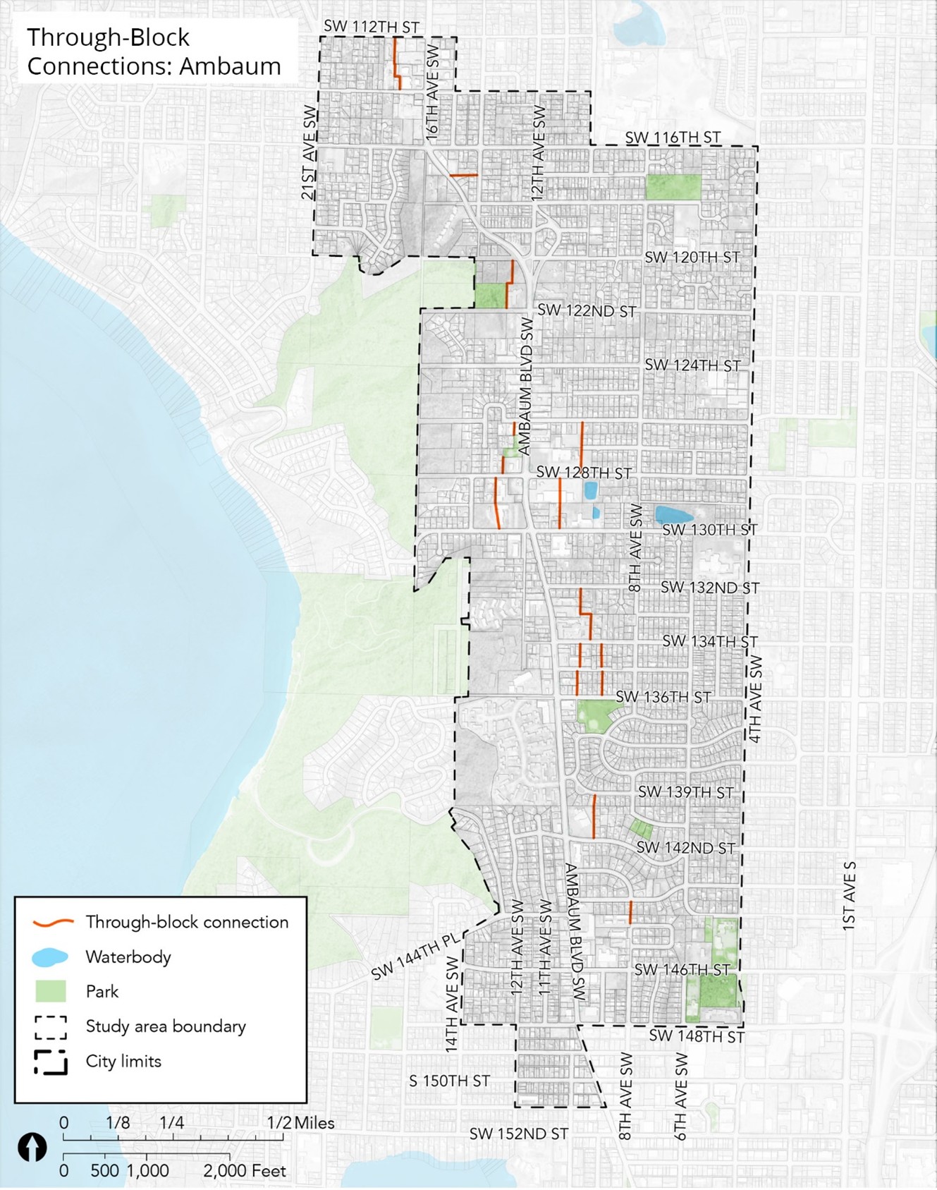
Figure 19.47.130.3.B: Required Through-Block Connections and Trails Map – Boulevard Park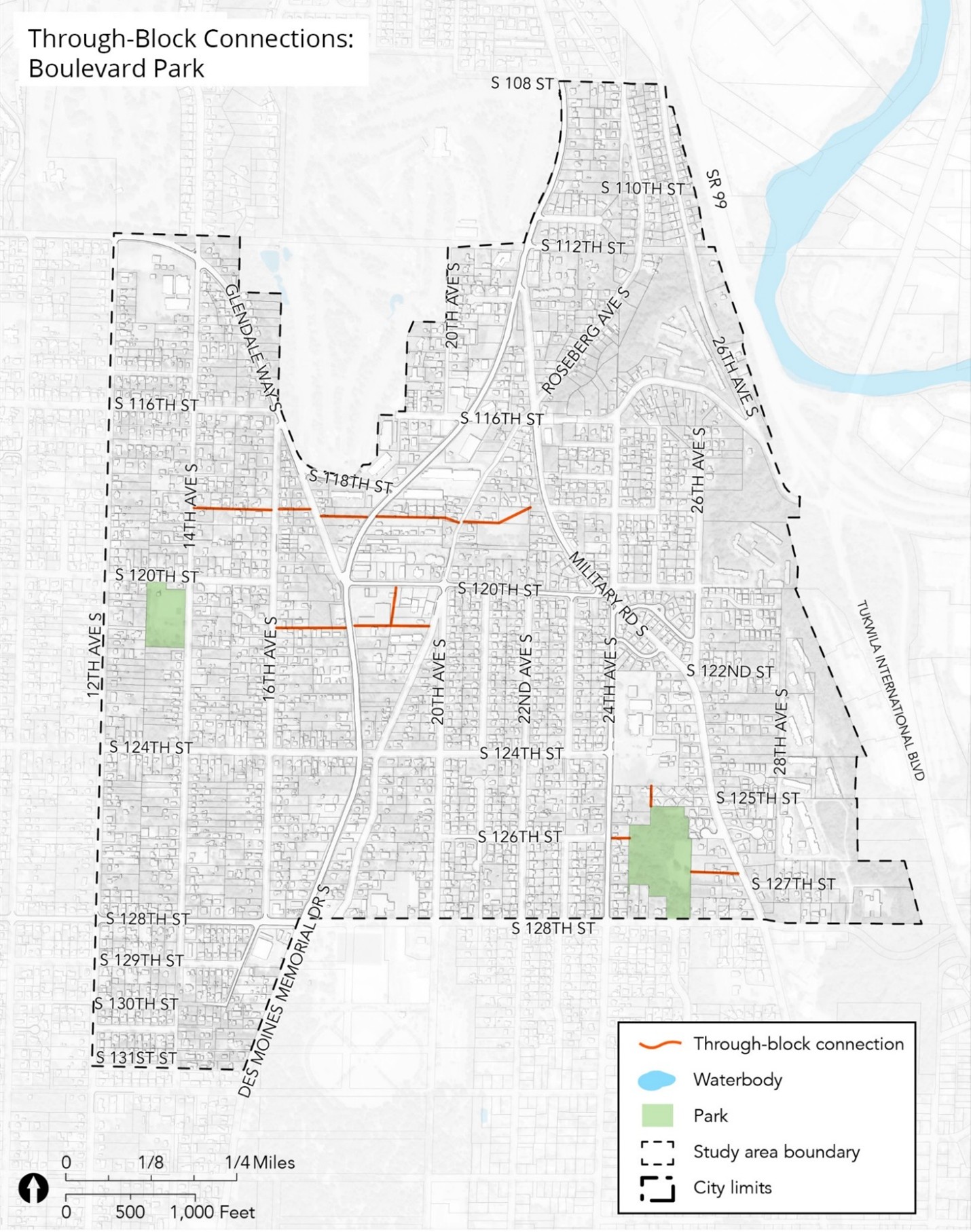
4. TBC Improvement Standards. TBCs required in subsections (1) and (2) of this section must meet the following improvement standards:
A. Required TBCs shall be built by developers as development occurs.
B. TBC Design Options and Block Frontage Standards. Unless otherwise noted, developments may choose to integrate such connections in a variety of forms, including routes shared with vehicles. A combination of designs may also be used on each site.
i. Trail design, as set forth in BMC 19.17.300.
ii. Alley design, consistent with Burien’s adopted street standards. The alley design option is only permitted on blocks featuring storefronts complying with Class B Pedestrian-Oriented Street block frontage per BMC 19.47.240 along at least 50% of the block’s perimeter frontage.
iii. Woonerf (shared street) design. This is a 20-foot-wide two-way shared travel lane featuring concrete, unit paving, or other similar decorative and durable surface material. Asphalt is prohibited.
iv. A private street featuring a separate pathway, consistent with Burien’s adopted street standards.
C. TBC Development Frontages. To ensure that TBCs are welcoming to pedestrians, Table 19.47.130.4 below provides standards for development “frontages” options. Unless otherwise noted, developments may integrate such connections in a variety of forms, including routes shared with vehicles. A combination of designs may also be used on each site.
|
TBC design. |
Development frontage options |
|
Trail design. |
• Pedestrian-oriented street block frontage per BMC 19.47.240. |
|
Woonerf (shared street) design. |
|
|
Private street. |
|
|
Alley design. |
While the above development frontage options are desirable, there are no minimum standards for alley development frontages. |
D. Required Connections and Public Access Easement. If an applicant owns a lot containing a proposed TBC within it or along the edge of the property, the applicant must provide such TBC in conjunction with their project development as a public access easement. Single-detached residential developments are exempt from this standard.
E. Alignment. Specific alignments for new, widened, or extended TBCs will be determined during the development review process for applicable sites.
F. Half-TBC Improvements. For those required TBCs located on a property line, one-half improvements shall be made as determined by the Director.
G. Accessibility. TBCs must always be accessible to the public.
H. Maintenance. Maintenance of any trail corridor or improvements retained in private ownership shall be the responsibility of the owner or other separate entity capable of long-term maintenance and operation in a manner acceptable to the parks division.
I. Cantilever Design. Buildings may project or cantilever into minimum required easement areas on building levels above the connection provided a 13-foot, six-inch vertical clearance is maintained and all other regulations are met. [Ord. 849 § 61, 2024]
Article 3 – Block-Frontage Standards
19.47.200 Block-frontage standards – User guide. Revised 2/25
Block frontages refer to the disposition of buildings and site development features as viewed from the street. This starts at the back of the sidewalk at or near the front property line and includes building setbacks, orientation, transparency, ground-level uses, driveways and parking location, and landscaping along the block frontages. Site orientation standards for individual properties depend on the block frontage designated for that location. The following steps will help in using this article:
1. Determine if the property is located on a designated Pedestrian-Oriented Street per BMC 19.47.220. If it is, then go to BMC 19.47.240 to see the standards for development with the Pedestrian-Oriented Street block-frontage type designation.
2. If the street fronting the property is not a designated Pedestrian-Oriented Street, it is subject to the provisions of “Typical” block frontages in BMC 19.47.250.
3. These two-block block-frontage designation types, along with “Access Corridor” frontage provisions of BMC 19.47.270, may apply to development adjacent to the required Through-Block Connections set forth in BMC 19.47.130.
4. Lastly, BMC 19.47.280 and 19.47.290 involve corner sites. BMC 19.47.280 provides clarifications on how the block frontage standards are applied on corner sites. BMC 19.47.290 calls out special “High Visibility Street Corners” and applicable design standards for such sites. [Ord. 849 § 61, 2024]
19.47.210 Purpose. Revised 2/25
1. Achieve the envisioned character for Burien’s downtown and other mixed-use and multifamily areas.
2. Enhance pedestrian environments by emphasizing activated ground-level block-frontage designs for commercial, mixed-use, and multifamily developments.
3. Minimize potential negative impacts of driveways and off-street parking facilities on the streetscape.
4. Promote good visibility between buildings and the street for security for pedestrians and to create a more welcoming and interesting streetscape. [Ord. 849 § 61, 2024]
19.47.220 Block-frontage designation maps. Revised 2/25
The block-frontage designations established by this chapter are maintained under the director’s direction. All notations, references, and other information shown have the same force and effect as if fully described in this title.
1. Designated Pedestrian-Oriented Street block frontages in the Ambaum Corridor – Northern Section.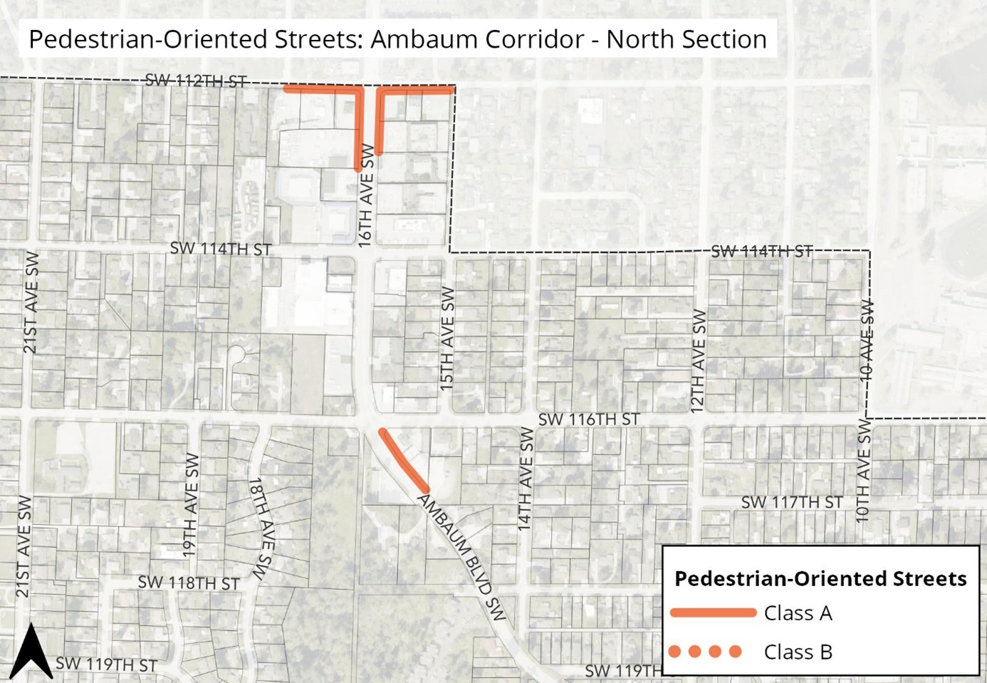
2. Designated Pedestrian-Oriented Street block frontages in the Ambaum Corridor – Central Section.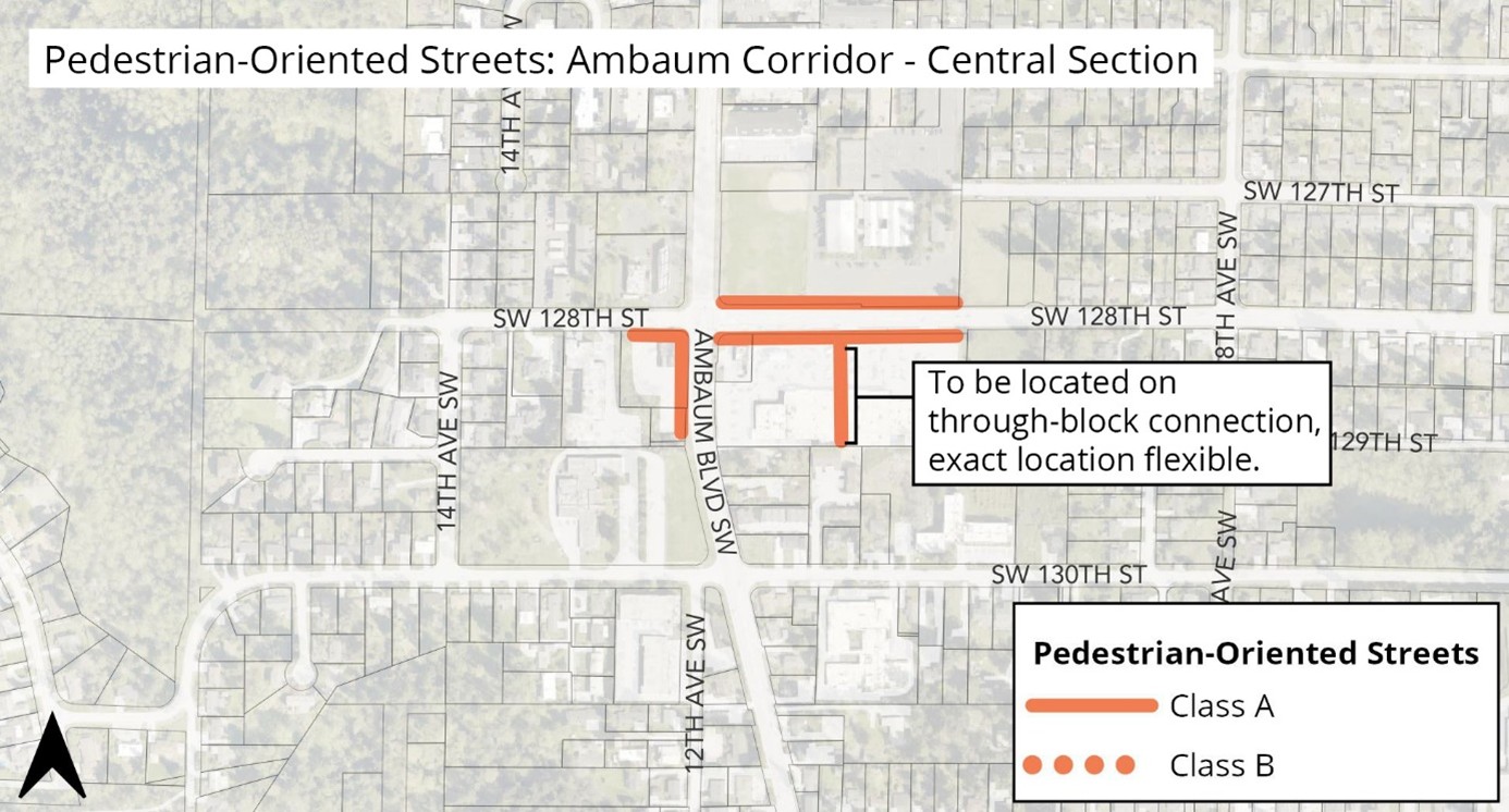
3. Designated Pedestrian-Oriented Street block frontages in the Ambaum Corridor – Southern Section.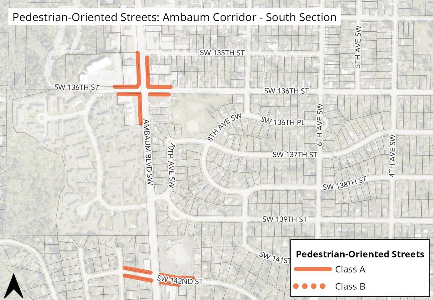
4. Designated Pedestrian-Oriented Street block frontages on First Ave.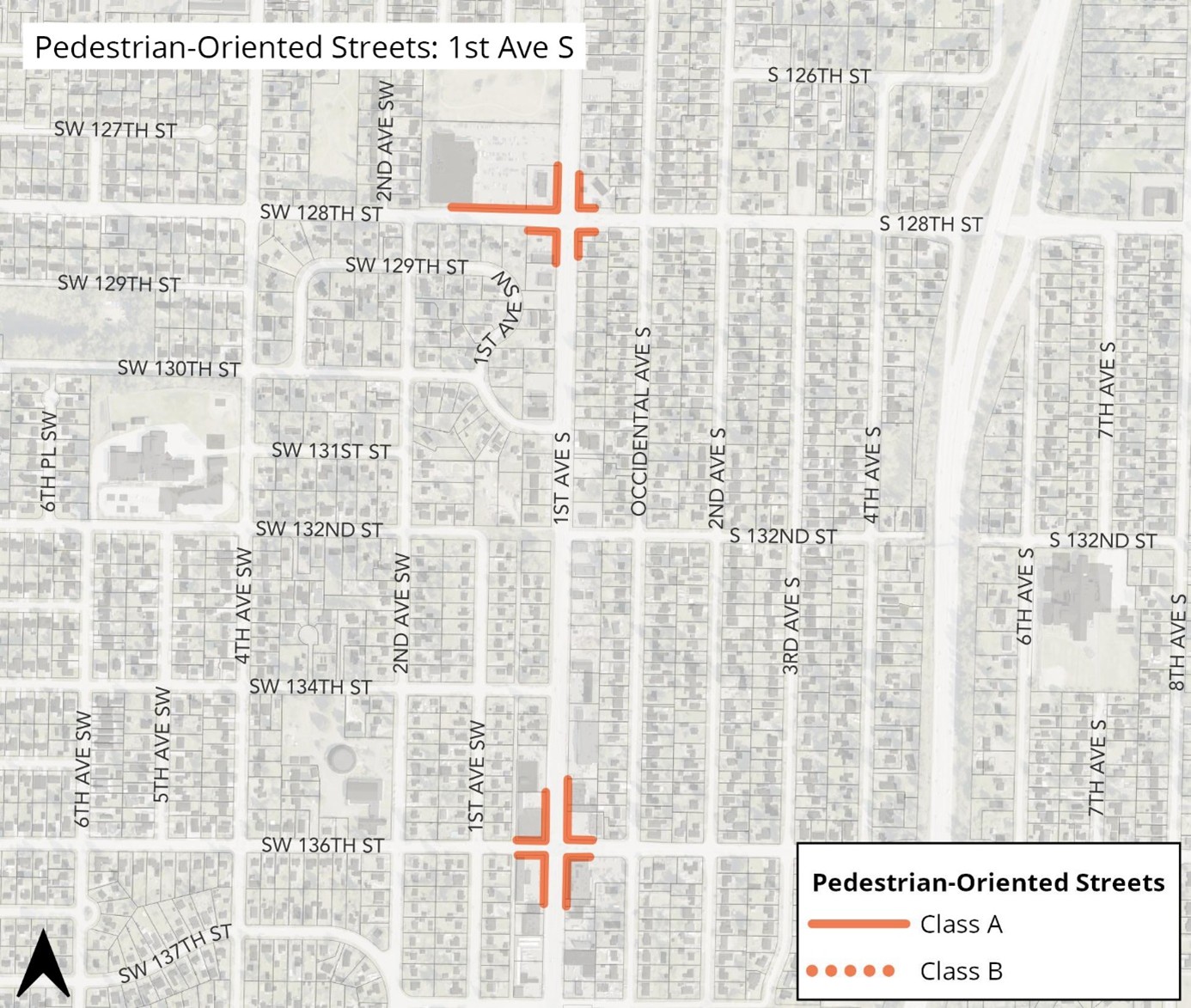
5. Designated Pedestrian-Oriented Street block frontages in Boulevard Park.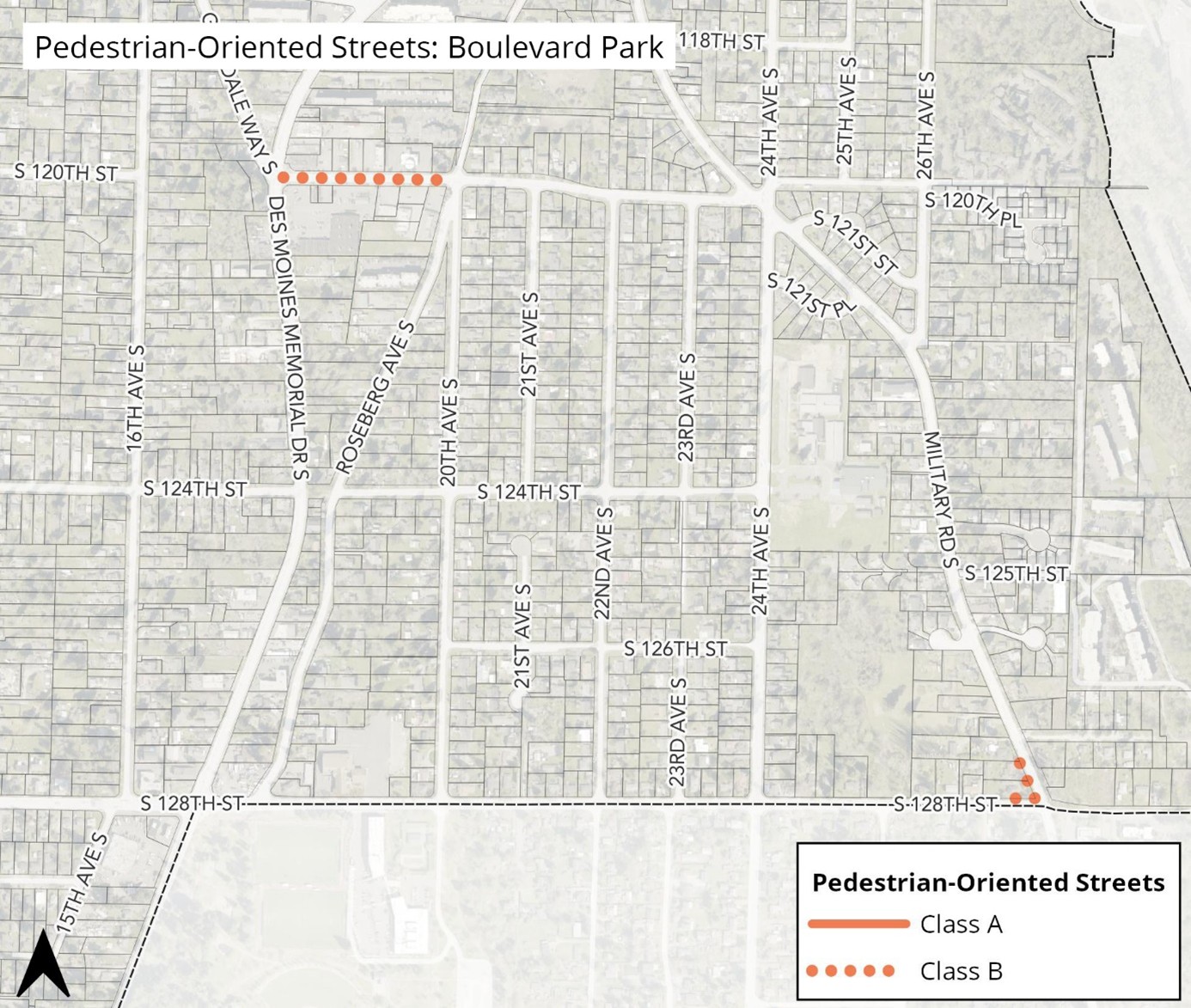
6. Designated Pedestrian-Oriented Street block frontages in Urban Center.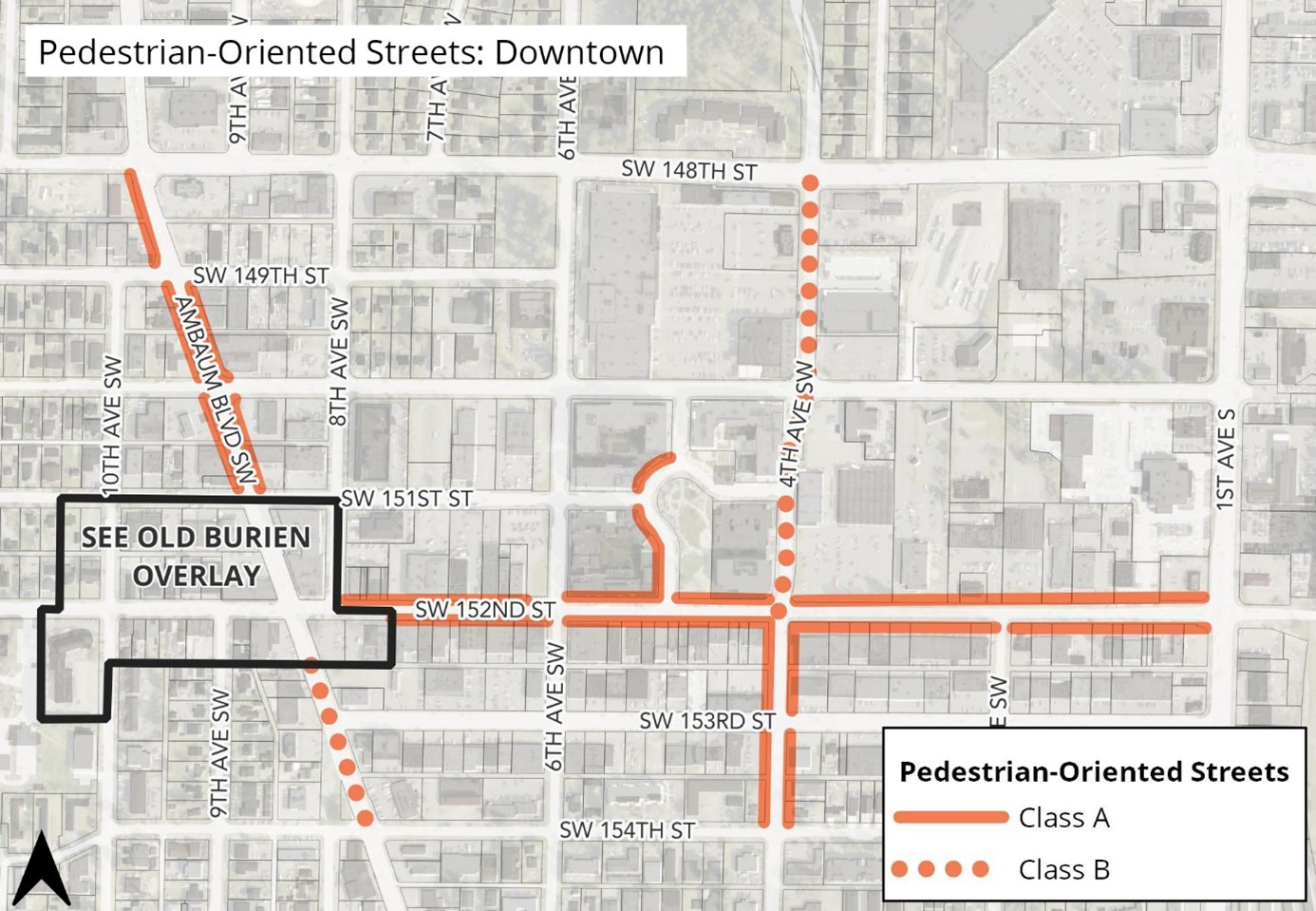
[Ord. 849 § 61, 2024]
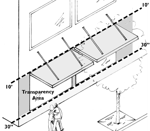
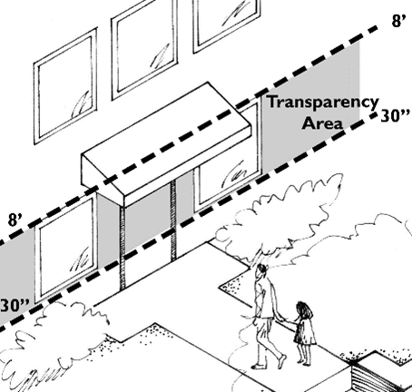
19.47.230 About the transparency standards. Revised 2/25
All block-frontage designations contain distinct minimum façade transparency standards. The purposes of these standards are to maintain “eyes on the street” for safety and create welcoming pedestrian environments. Table 19.47.230 below includes details on how they are measured.
|
Transparency Area |
||
|
Storefront on Pedestrian-Oriented Street |
Ground floor non-residential on Landscaped block frontage |
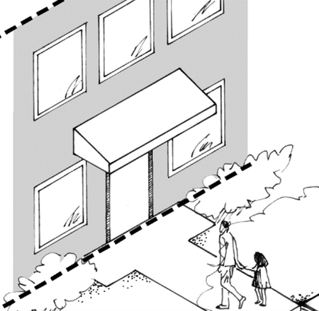
Residential buildings and residential portions of mixed-use buildings with Land-scaped block frontage |
|
The transparency area is on the ground floor between 30" and 10' above sidewalk grade |
The transparency area is between 30" and 8' above grade. |
All vertical surfaces of the façade are used in the calculations. |
|
Other Transparency Provisions |
||
|
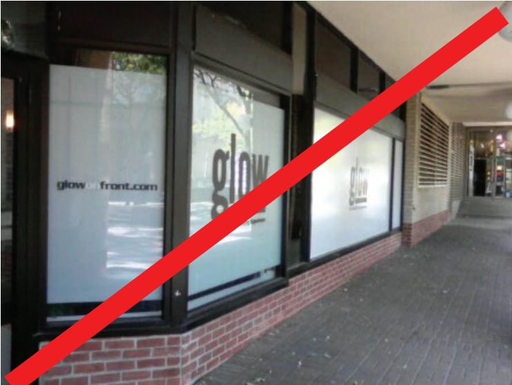
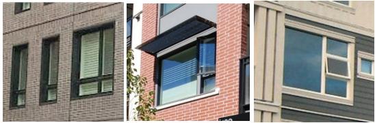
Windows must be transparent. Ground-level window areas for storefronts and other non-residential uses that are covered, frosted, or perforated in any manner that obscures visibility into the building must not count as transparent window areas. Also, mirrored glass and highly-reflective or darkly-tinted windows must not be counted as transparent windows. |
Covered windows |
Perforated sign |
|
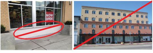
Display Windows and Parking Garages Display windows may be used for up to 25% of non-residential transparency requirements provided they are at least 30" deep to allow changeable displays, and the interior wall is non-structural so it can be removed if the windows are not used for display. Tack-on display cases, as shown in the far right example, do not qualify as transparent window areas. For parking garages (where allowed by block frontage standards), the left image illustrates how such a structure can meet (and not meet) the applicable transparency standards. |
Integrated display windows
Parking garage with windows |
Tack-on display cases
Parking garage without windows |


[Ord. 849 § 61, 2024]
19.47.240 Pedestrian-oriented street block-frontage standards. Revised 2/25
1. Purpose. Pedestrian-Oriented Street block frontages are the most vibrant and active shopping and dining areas within Burien. Blocks designated as Pedestrian-Oriented Street block frontages include continuous storefronts placed along the sidewalk edge with small-scale shops and many business entries.
There are two tiers of Pedestrian-Oriented Street block frontage designations: Class A and Class B. Class B Pedestrian-Oriented Street block frontages have slightly relaxed ground-level use, transparency, and weather protection standards.
Figure 19.47.240.1
Pedestrian-Oriented Streets Vision and Key Standards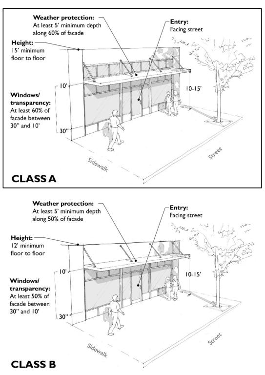
2. Applicability. Standards herein apply to:
A. Designated Class A or Class B Pedestrian-Oriented Street block frontages as set forth in BMC 19.47.220.
B. As an option to construct a storefront building for development in Mixed-Use zones not designated as a Class A or Class B Pedestrian-Oriented Street. Buildings or portions thereof sited adjacent to a public sidewalk must meet minimum standards for Class B Pedestrian-Oriented Streets herein.
C. As an option for mixed-use buildings in the R-4 or R-5 zone. Such buildings or portions thereof sited adjacent to a public sidewalk must meet minimum standards for Class B Pedestrian-Oriented Streets herein.
3. Standards. Applicable development must comply with the standards in Table 19.47.240.3 below:
|
The Ü symbol refers to DEPARTURE opportunities as set forth in BMC 19.65.105.5 with supplemental criteria in sub-section (4) of this section. |
||
|---|---|---|
|
Element |
Class A Pedestrian-Oriented Street Standards |
Class B Pedestrian-Oriented Street Standards |
|
Ground-level |
|
|
|
Land use |
Residential uses are prohibited except lobbies and accessory uses associated with multifamily residential uses are allowed if they are limited to 30% of block-frontages. |
Residential uses are prohibited except: • Live/work units featuring ground-level space that complies with minimum floor-to-floor height and non-residential space depth herein. • Artists’ studio/dwellings complying with BMC 19.17.330. • Lobbies and accessory uses associated with multifamily residential uses are allowed if they are limited to 60% of block-frontages. |
|
Floor-to-floor height for new buildings (applies to the minimum non-residential space depth) |
15' minimum. |
12' minimum. |
|
Non-residential space depth |
30' minimum, provided at least 50% of the space is at least 50' deep. Ü |
30' minimum. Ü |
|
Building placement |
Buildings must be placed at the back edge of the required sidewalk. Additional setbacks at corners may be required to meet BMC 19.17.240 sight distance requirements. Additional setbacks are allowed for a widened sidewalk or pedestrian-oriented space per BMC 19.47.320.4. |
|
|
Building entrances |
Primary building entrances must face the street. For corner buildings, see BMC 19.47.280. |
|
|
Façade transparency (see BMC 19.47.230) |
At least 60% of the transparency area. Ü |
At least 50% of the transparency area. Ü |
|
Weather protection |
Weather protection over sidewalks is required along at least 60% of the storefront façade, and it must be a minimum of 6' deep and have 10' to 15' of vertical clearance. Ü The Director may require reduced-width weather protection where necessary to avoid interfering with street trees, streetlights, street signs, or extending beyond the edge of the sidewalk. |
Weather protection over sidewalks is required along at least 50% of the storefront façade and must be a minimum of 5' deep and have 10' to 15' of vertical clearance. Ü The Director may require reduced-width weather protection where necessary to avoid interfering with street trees, streetlights, street signs, or extending beyond the edge of the sidewalk. |
|
Parking location |
New ground-level (surface or structured) parking adjacent to the street is prohibited. Parking may be placed below, above, and/or behind store-fronts. Driveways are allowed from designated Pedestrian-Oriented Streets only when no other option exists. |
New ground-level (surface or structured) parking adjacent to the street is prohibited. Parking may be placed below, above, and/or behind storefronts. Driveways are allowed from designated Pedestrian-Oriented Streets only when no other option exists. Exception: For Class B Pedestrian-Oriented Streets in the Boulevard Park planning area and on non-designated Pedestrian-Oriented Streets where the development chooses to integrate a storefront building, parking may be located to the side of a building, provided such parking area occupies no more than 50% of the block frontage. |
4. Departure Criteria. Departures from the standards in Table 19.47.240.3 that feature the “Ü” symbol will be considered per BMC 19.65.105.5, provided the alternative proposal meets the purpose of the standards and the following criteria:
A. Retail Space Depth. Reduced depths on up to 25% of the applicable block frontage will be considered where the applicant successfully demonstrates the proposed alternative design and configuration of the space is viable for a variety of permitted retail uses.
B. Facade Transparency. Departures for facade transparency in the transparency area may be reduced to a minimum of 40% for block frontages if the façade design between ground-level windows provides visual interest to the pedestrian and mitigates the impacts of blank walls.
C. Weather Protection. The reduced extent (to no less than 50% of block frontages) or width of weather-protection features (to no less than four feet in width) will be considered provided the designs are proportional to architectural features of the building and building design trade-offs (elements that clearly go beyond minimum building design standards in this chapter) meet the purpose of the standards. [Ord. 849 § 61, 2024]
19.47.250 Typical block-frontage standards. Revised 2/25
1. Purpose. To provide for flexibility in the design of block frontages in Mixed-Use zones while ensuring that block frontages create a pedestrian-friendly environment.
2. Applicability. Standards herein apply to all development in the Mixed-Use zones, not designated as a Class A or Class B Pedestrian-Oriented Street.
3. Standards. Applicable development may choose between the Pedestrian-Oriented Street block frontage design, as set forth in Table 19.47.240.3, or the Landscaped block frontage design, as set forth in Table 19.47.260.3, or some combination of the two as clarified in this section.
4. Blending Frontages. Given that properties within Mixed-Use zones not designated as a Class A or Class B Pedestrian-Oriented Street have options to integrate both storefront and landscaped block-frontage forms they can also blend the design forms in two ways:
A. Portions of the building may be designed to comply with Class B Pedestrian-Oriented Street block frontage standards set forth in BMC 19.47.240 and other portions of the building comply with Landscaped block frontage standards set forth in BMC 19.47.260.
B. Buildings may also employ designs that are a hybrid of two block frontage types, where they feature a small, landscaped setback (less than what is required under the Landscaped block frontage standards), provided the window transparency levels increase towards Class B Pedestrian-Oriented Street requirements at a proportional rate as the setback gets smaller. Weather protection isn’t required in areas where there are more than 16 inches of landscaping adjacent to the façade (measured perpendicular to the façade). All other standards for Class B Pedestrian-Oriented Street block frontages in Table 19.47.240.3 apply. [Ord. 849 § 61, 2024]
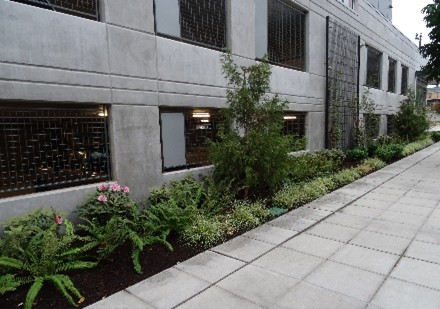
19.47.260 Landscaped block-frontage standards. Revised 2/25
1. Purpose. To emphasize landscaped street setbacks, clear pedestrian connections between the building and the sidewalk, and minimized surface parking lots along the frontages.
2. Applicability. Standards herein apply to all development in the R-4 and R-5 zones and as an option for the development of Mixed-Use zones not designated as Class A or Class B Pedestrian-Oriented Streets. Exception: Mixed-use buildings in the R-4 or R-5 zone may choose to develop storefront buildings complying with the Class B Pedestrian-Oriented Street block frontage provisions as set forth in BMC 19.47.240.
3. Standards.
A. Applicable developments are subject to the Landscaped block frontage standards set forth in Table 19.47.260.3.
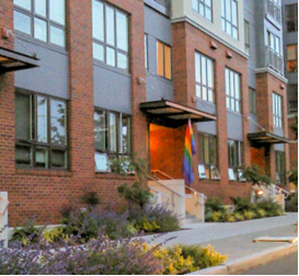
Figure 19.47.260.3: Landscaped Frontage Vision and Key Standards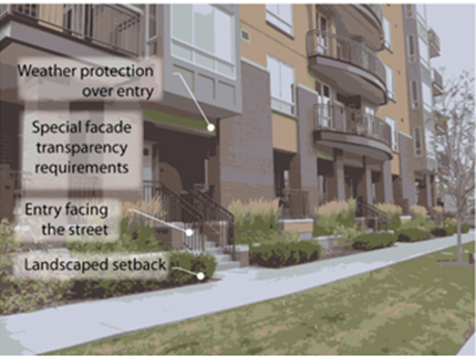
|
The Ü symbol refers to DEPARTURE opportunities set forth in BMC 19.65.105.5 with supplemental criteria in subsection (4) of this section. |
|
|---|---|
|
Element |
Standards |
|
Ground-level Land use |
|
|
Building placement |
10' minimum setbacks are required. Ü |
|
Building entrances |
Building entries must face the street or a pedestrian-oriented space (BMC 19.47.320.4) that is adjacent to the street. For corner sites, see BMC 19.47.280. |
|
Façade transparency (see BMC 19.47.230) |
For buildings with ground-level non-residential uses, at least 40% of the transparency area. Ü For buildings with ground-level residential uses, at least 20% of the facade. Ü |
|
Weather protection |
Weather protection at least 3' deep must be provided over individual residential and commercial tenant entries and at least 5' deep for shared residential and professional office entries. |
|
Parking location |
Surface-level parking must be located on the side or rear of buildings. For sites with multiple buildings, no more than 50% of arterial street block frontages may be occupied by parking and vehicular access areas. Ü Where integrated within a building, ground-level parking must not be visible from the street. Where parking is integrated within a building at or near ground-level it must be completely screened by landscaped berms and/or Type I or II Landscaping as set forth in BMC 19.25.050. Townhouse garages may face a non-arterial street if no more than 50% of the linear ground-level building frontage is occupied by garage doors. Driveways must be no wider than 12' for individual driveways and 20' when shared. Driveways must be located to maximize available on-street parking, where street widths allow. |
|
All areas between the sidewalk and the building must be landscaped, except for pathways, porches, decks, and other areas meeting the definition of pedestrian-oriented space (BMC 19.47.320.4). Landscaped areas above must contain Types II, III, or IV Landscaping (as defined in BMC 19.25.050) and may incorporate rain gardens and other forms of stormwater management. All areas between the sidewalk and surface parking lot or outdoor storage areas must be landscaped with a planting strip at least 10' wide. Type III Landscaping must be used to screen parking lots, and Type I Landscaping must be used to screen outdoor storage areas. Ü Certain industrial uses allowed in Mixed-Use zones require wider landscaping buffers as set forth in Table 19.25.040-1. |
|
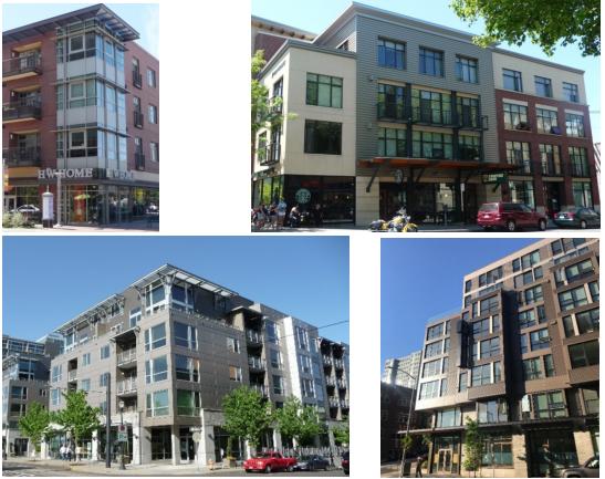
4. Departure Criteria. Departures to the landscaped block-frontage standards in Table 19.47.260.3 that feature the Ü symbol will be considered per BMC 19.65.105.5, provided the alternative proposal meets the purpose of the standards and the following criteria:
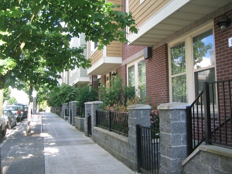
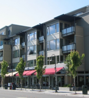
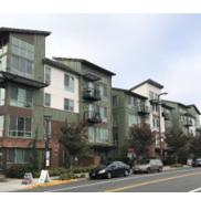
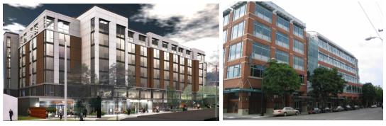
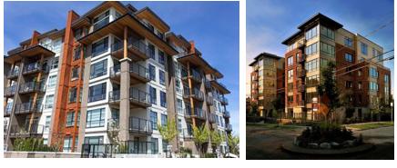
A. Building Placement: Reduced setbacks (down to a minimum of six feet) will be considered where the ground floor is elevated a minimum average of 30 inches (required when the ground floor setback is less than ten feet) and design treatments that create an effective transition between the public and private realm. For example, a stoop design or other similar treatments that utilize a low fence or retaining wall, and/or hedge along the sidewalk may provide an effective transition (see Figure 19.47.260.4 for examples).
B. Façade Transparency: Façade transparency in the transparency area may be reduced from the minimum by 50% if the façade design between ground-level windows provides visual interest to the pedestrian and mitigates the impacts of blank walls.
|
|
|
|
The apartment building (left image) includes a street setback of about 6-8 feet and features a landscape planter, an elevated ground level, and generous window transparency. The elevated-stoop frontages (right image) are another acceptable reduced setback departure example. The combination of landscaping elements, façade transparency, low fencing, and façade materials and detailing help to create an effective transition between the public and private realms. |
|
[Ord. 849 § 61, 2024]
19.47.270 Access corridor frontage standards. Revised 2/25
1. Purpose. Access Corridor frontage standards provide an eyes-on-the-pathway to create a safe and welcoming through-block connection while preserving the privacy of adjacent ground-level residential units.
2. Applicability. These standards are one of multiple block frontage options for development adjacent to a through-block connection as set forth in BMC 19.47.130.
3. Standards. Access corridors may use designs that include shared vehicular access, are pedestrian-only, or are a combination thereof.
A. Building elevations facing an access corridor must feature at least 10% window transparency. Ü
B. Where ground-level residential uses are within five feet of a shared lane or pathway, at least one of the following design features must be integrated to enhance the safety and privacy of adjacent residential units:
i. Windows must be placed at least six vertical feet above the access corridor.
ii. A combination of landscaping, planter walls, and/or elevated ground floor (at least one foot above access corridor grade) that meets the purpose of the standards.
C. Where non-residential ground-level uses abuts an access corridor, at least 25% of the applicable building elevation between four and eight feet above the ground-floor surface elevation must be transparent. Ü
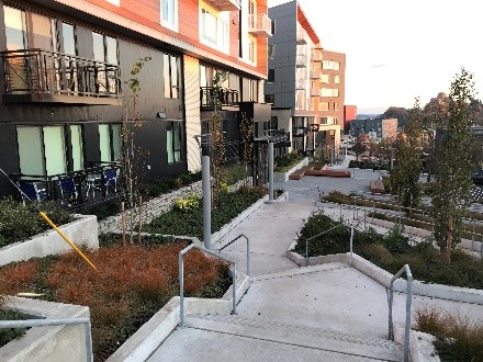
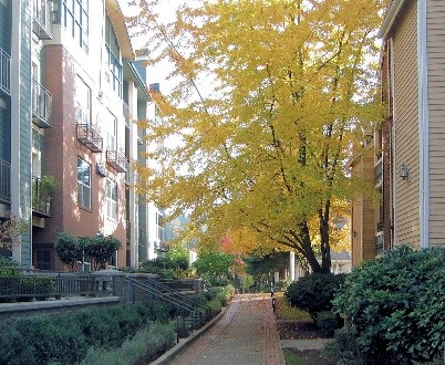
|
Access-corridor example illustrating shared pedestrian and vehicular access. |
||
|
Pedestrian Access-Corridor Examples |
||
|
|
|
|

[Ord. 849 § 61, 2024]
19.47.280 Corner sites. Revised 2/25
Where a property fronts onto more than one street, each building frontage must comply with the standards for the block frontage upon which it fronts, with the following clarifications:
1. Entrances. For corner sites, entrances may be provided on both streets, but only one entrance is required unless the site fronts a Pedestrian-Oriented Street on both sides, in which case the entrance shall be provided on the corner or on each street.
2. Transparency and weather protection standards associated with corner storefronts.
A. For corner sites featuring a Pedestrian-Oriented Street block frontage designation on one street, corner buildings must meet applicable Pedestrian-Oriented Street block frontage transparency and weather protection standards. Such storefront buildings may be built up to the sidewalk along the other block frontage, provided they contain at least 50% of the required transparency and weather protection on Pedestrian-Oriented Street block frontages. Where such corner buildings contain additional storefront uses on the non-Pedestrian-Oriented Street block frontage, then those storefronts are subject to the full Pedestrian-Oriented Street block frontage transparency and weather protection standards.
B. For street corners with Pedestrian-Oriented Street designations on both block frontages, buildings must employ full transparency on the dominant frontage (based on the frontage width or established neighborhood pattern), a 50% reduction in minimum transparency, and weather protection is permitted on the secondary façade associated with the corner establishment. Other storefront uses of the corner establishment are subject to the full Pedestrian-Oriented Street block frontage transparency and weather protection standards.
C. For corner storefront establishments without a Pedestrian-Oriented Street designation on either street, the block frontage containing the entry is subject to the full Pedestrian-Oriented Street block frontage transparency and weather protection standards. The secondary block frontage associated with the corner establishment must contain at least 50% of the required transparency and weather protection on Pedestrian-Oriented Street block frontages. [Ord. 849 § 61, 2024]
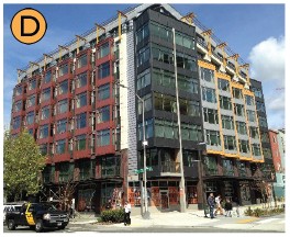
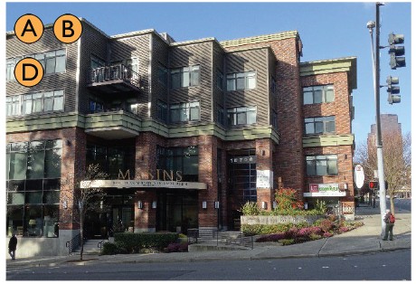
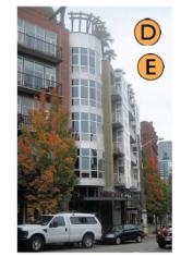
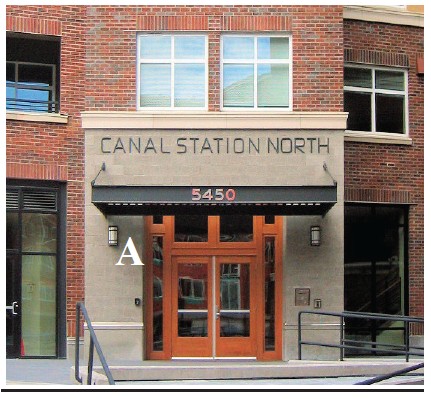
19.47.290 High-visibility street corners. Revised 2/25
1. Description/Purpose. The high visibility street-corner requirements apply to the following sites to accentuate designated street corners with high visibility to the public:
A. Street corners where at least one block of frontage is designated Pedestrian-Oriented Street.
B. Street corners adjacent to RapidRide stations.
For other corner sites, see BMC 19.47.280 for standards and clarifications.
2. Standards. At least one of the following special features must be included (Figure 19.47.290.2 below illustrates acceptable examples):
A. Corner plaza.
B. Cropped building corner with a special entry feature.
C. Decorative use of building materials at the corner.
D. Distinctive façade articulation.
E. Sculptural architectural element.
F. Other decorative elements that meet the standard’s purpose.
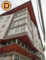
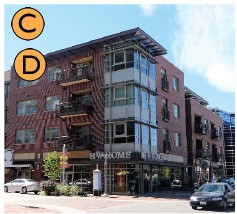
|
|
|
|
|
|
|
|
|
The letters on the images refer to the special feature options above that are integrated into the design. |
||
[Ord. 849 § 61, 2024]
Article 4 – Site Planning
19.47.300 Site Planning – Purpose Revised 2/25
1. To promote thoughtful layout of buildings, parking areas, circulation, service, landscaping, and amenity elements.
2. Enhance Burien’s visual character.
3. Promote compatibility between developments and uses.
4. Enhance the function of developments. [Ord. 849 § 61, 2024]
19.47.310 Interior/side and rear yard setbacks Revised 2/25
1. Purpose.
A. To promote the functional and visual compatibility between developments, particularly between zones of different intensity.
B. To protect the privacy of residents on adjacent properties.
2. Interior setback standards. Setback standards are set forth in BMC 19.15.015.2.B for R-4 and R-5 zones and BMC 19.15.020.2.B for MU zones.
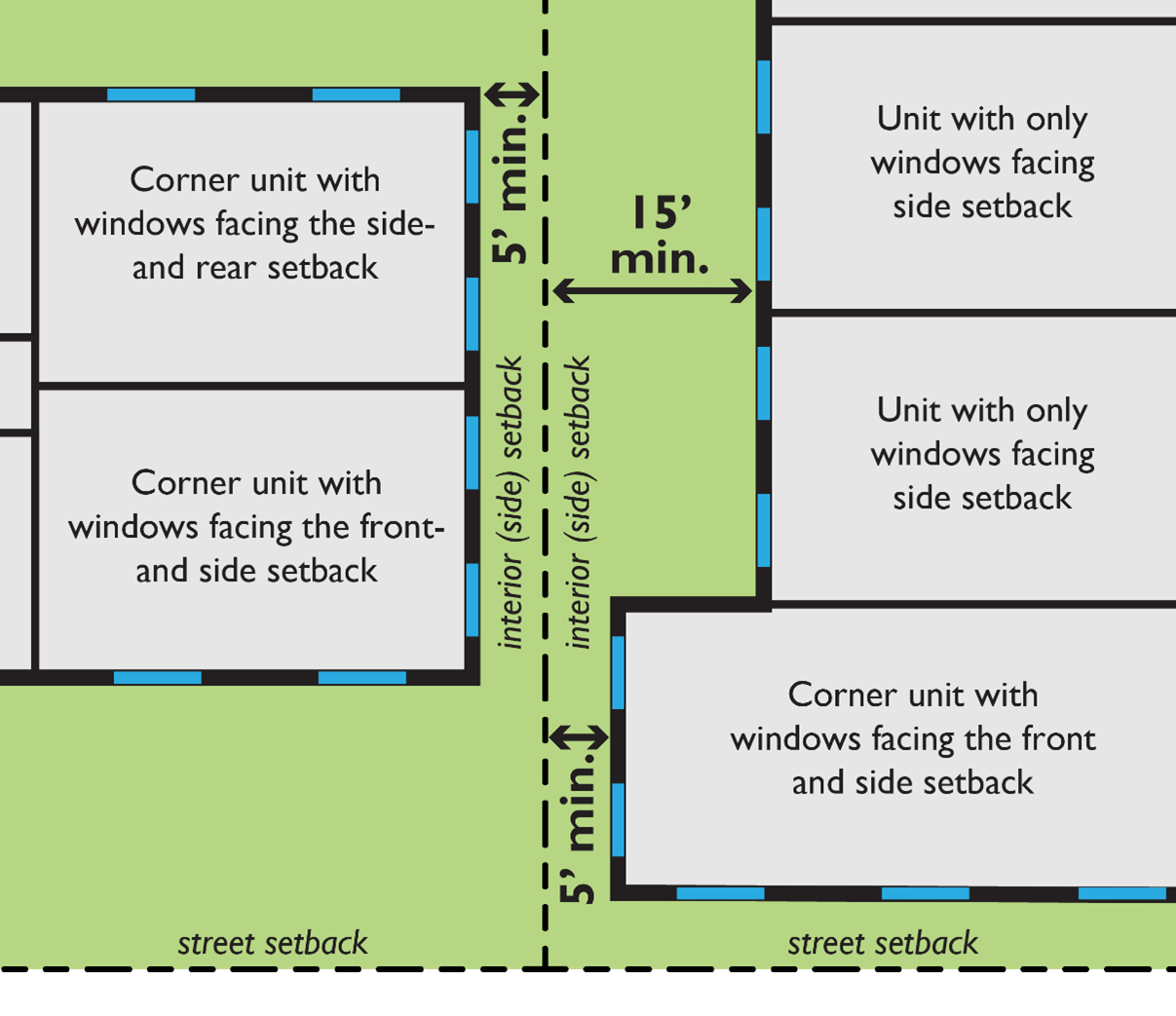
3. Light and air access and privacy near interior property lines. Buildings or portions thereof containing multifamily dwelling units whose only solar access (windows) is from the applicable side or rear of the building (facing towards the interior property lines) must be set back from the applicable property lines at least 15 feet. See Figure 19.47.310.3. For such building elevations taller than four stories, floors above the fourth floor must be set back at least 20 feet from the applicable property lines. Note: These standards do not apply to interior property lines adjacent to a street, access corridor, or easement where no building may be developed.
Departures will be allowed where it is determined that the proposed design will not create a compatibility problem in the near and long term based on the unique site context.
|
Note that the minimum setbacks noted above only apply to buildings (and portions thereof) featuring the stated characteristics. |
[Ord. 849 § 61, 2024]
19.47.320 Internal open space Revised 2/25
1. Purpose.
A. Create a usable space suitable for leisure or recreation for residents.
B. Create open space that contributes to the residential setting.
C. Provide plazas that attract shoppers to commercial areas.
D. Provide plazas and other pedestrian-oriented spaces in commercial areas that enhance the employees’ and public’s opportunities for active and passive activities, such as dining, resting, people-watching, and recreation.
E. Enhance the development character and attractiveness of commercial development.
2. Usable Residential Recreational Space.
A. All residential developments, including residential portions of mixed-use development, must provide minimum usable recreational space equal to 100 sq. ft. per dwelling unit for studio units, 125 sq. ft. for one-bedroom apartment dwellings, and 150 sq. ft. per dwelling unit for dwellings with two or more bedrooms. The required recreational space may be provided in a combination of ways:
i. Shared recreational space. Required recreational space may be shared recreational space available to all residents if it meets the requirements of subsection (2)(B) of this section.
ii. Ground/grade-level individual outdoor space. All the required unit recreational space may be provided by ground-level outdoor space that is adjacent and directly accessible to the subject unit. Such recreational spaces must be:
a. Outdoor spaces may be in the front, side, or rear yard, provided they are generally level, feature no dimension less than ten feet, and are enclosed by a fence, railing, and/or hedge at least 32 inches in height to qualify.
b. Private porches may qualify as outdoor space if they are at least 36 sq. ft. in area, with no dimension less than six feet.
Individual ground-level open space that exceeds minimum requirements must not be used in the calculations for determining the minimum usable recreational space requirements for other units in the development.
iii. Balconies and other similar private outdoor spaces. Up to 50% of the required recreational space for a unit may be provided by private balconies provided such spaces are at least 36 sq. ft. in area, with no dimension less than four feet (not including railings), to provide a space usable for human activity.
iv. Common indoor recreation areas. Up to 50% of the required recreational space may be provided by common indoor recreation areas meeting the following conditions:
a. The space must meet ADA standards and must be in a visible area, such as near an entrance, lobby, or high-traffic corridors.
b. The space must be designed specifically to serve interior recreational functions and not merely be leftover unrentable space used to meet the open space requirement.
v. Shared roof decks. For apartment buildings, up to 50% of the required recreational space may be provided by shared roof decks located on the top of buildings which are available to all residents and meet the requirements below. For mixed-use buildings, 100% of the required recreational space may be provided by shared roof decks. Design requirements:
a. Space must feature hard surfacing and provide amenities such as seating areas, landscaping, and/or other features that encourage use.
b. Space must integrate landscaping elements (at least 20% of the space) that enhance the character of the space and encourage its use.
Figure 19.47.320.2.A
Rooftop Deck Examples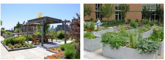
B. Shared recreational space design requirements. Shared recreational space can include landscaped courtyards or decks, entrance plazas, gardens with pathways, children’s play areas, pools, and water features provided they are accessible to all residents of the development. Accessible areas used for storm-water retention, infiltration, or other multipurpose recreational and/or green spaces that meet the design criteria herein may qualify as shared recreational spaces.
Special requirements for shared recreational spaces include the following:
i. Shared recreational spaces must be located in centralized areas that are visible from units within the development.
ii. Required setback areas must not count as shared recreational space unless the design of the space meets the standards herein.
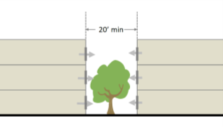
iii. Shared recreational space must feature no dimension less than 15 feet to provide functional leisure or recreational activity. Wider minimum dimensions are required perpendicular to building elevations containing windows of dwelling units whose only solar access is from the applicable building wall. Specifically:
a. Twenty feet minimum for such elevations up to three stories tall.
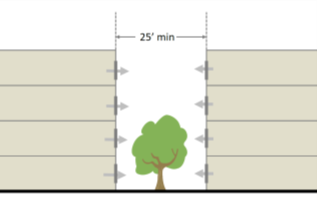
b. Twenty-five feet minimum for such elevations four stories tall.
c. Thirty feet minimum for such elevations five or more stories tall.
iv. Shared recreational spaces must feature paths or walkable lawns, landscaping, seating, lighting, and play structures, sports courts, or other pedestrian amenities to make the area more functional and enjoyable for a range of users.
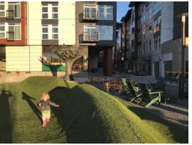
v. Shared recreational spaces (or at least one shared recreational space for each development) must integrate design elements and features that function as play areas for preadolescent children. This includes natural, creative play elements for free and/or structured play. These elements do not have to be overtly for play but should support, allow, and even encourage play by children. For instance, ground slides from one level to another, tricycle tracks, swings hung from arbors or trees, paths that meander and are of varying materials and widths, water that can be manipulated, outdoor rooms made from landscape or rocks, berms, and hills.
vi. Shared recreational space must be separated from ground-level windows, streets, service areas, and parking lots by landscaping, fencing, and/or other acceptable treatments that enhance safety and create an effective transition between public and private space.
vii. When possible, the space should be oriented to receive sunlight, facing east, west, or preferably south.
viii. Stairways and service elements located within or on the edge of shared recreational space must not be included in the open space calculations.
ix. Shared porches may qualify as shared recreational space, provided they are at least eight feet in depth and 96 sq. ft. in total area.
x. The space must be accessible to all residents of the development.
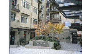
|
|
|
|
The upper left example is a courtyard over a parking deck. Notice the transition elements between the courtyard and adjacent residential units. The upper right courtyard is shared by ground-level commercial uses and apartments above. |
|
|
|
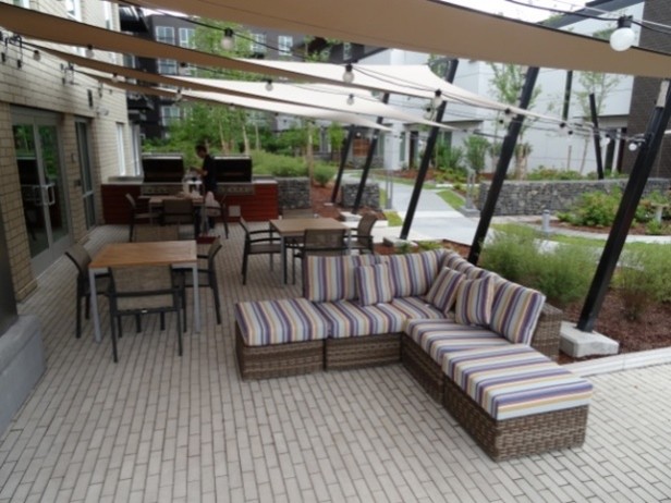
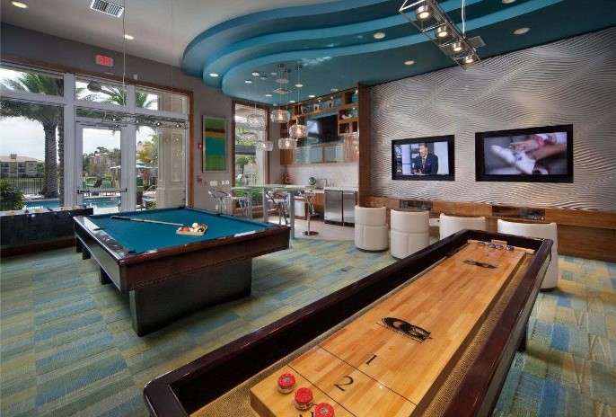
|
|
The left image above includes a covered gathering space with outdoor grills adjacent to a landscaped commons with a central pathway. The right image is an example of a shared indoor recreation space. |
|
|
|
|
|
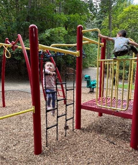
The left image above includes a turf play area with mounds for fun play. The right image shows traditional play equipment. |
|

|
|
20 feet minimum for elevations up to three stories tall. |
|
|
25 feet minimum for elevations four stories tall. |
|
|
30 feet minimum for such elevations five or more stories tall. |

3. Usable Commercial Open Space. New developments on designated Class A Pedestrian-Oriented Street block frontages and other developments with more than 10,000 sq. ft. of non-residential gross floor area must provide 400 sq. ft. of pedestrian-oriented space for each 100-lineal-feet of applicable non-residential block-frontage. Pedestrian-oriented spaces located adjacent to street corners may be counted for the frontages of both streets. Portions of sidewalks that are wider than the minimum required in BMC 19.47.120 may be used to meet up to 50% of this requirement.
4. Pedestrian-Oriented Space Design Criteria. This subsection describes the requirements and desired characteristics of pedestrian-oriented open space (which may be used to meet the requirements of subsection (3) of this section):
A. Required Pedestrian-Oriented Open Space Features.
i. Visual and pedestrian access into the site from a street, private access road, or non-vehicular courtyard.
ii. Paved walking surfaces of either concrete or approved unit paving. Form-in-place pervious concrete paving is allowed.
iii. The spaces must be in or adjacent to areas with significant pedestrian traffic to provide interest and security, such as adjacent to or visible from a building entry.
iv. At least two feet of seating area (a bench or ledge at least 16 inches deep and appropriate seating height) or one individual seat per 60 sq. ft. of plaza area or open space. Movable seating may be used to meet up to 50% of this requirement.
v. Landscaping components that add visual interest and do not act as a visual barrier. This could include planting beds, raised planters, and/or potted plants, or both.
B. Desirable pedestrian-oriented open space features include pedestrian amenities, such as site furniture, artwork, drinking fountains, shade structures, kiosks, or other similar features.
C. Features prohibited within a pedestrian-oriented open space:
i. Asphalt pavement.
ii. Adjacent service areas (e.g., trash areas, loading docks) that are not separated by landscaping.
iii. Adjacent chain-link fences.
iv. Adjacent “blank walls” without “blank wall treatment” (see BMC 19.47.450).
v. Outdoor storage.
|
|
|
|
|
|
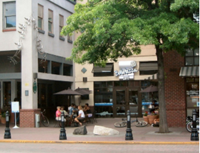
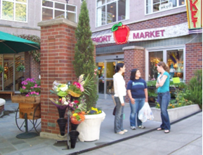
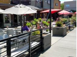
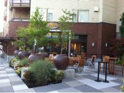
Figure 19.47.320.4.C.v.b
Example of a Small Pedestrian-Oriented Open Space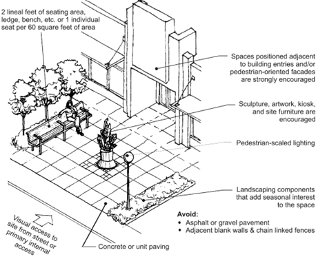
[Ord. 849 § 61, 2024]
19.47.330 Internal circulation and design. Revised 2/25
1. Purpose.
A. Improve the pedestrian and bicycling environment by making it easier, safer, and more comfortable to walk or ride among residences to businesses, street sidewalks, transit stops, and through parking lots to adjacent properties and connections throughout Burien.
B. Enhance access to on- and off-site open space areas and pedestrian/bicycle paths.
2. Internal Circulation.
A. All development must comply with the pedestrian access and circulation provisions of BMC 19.20.090.
B. Provide vehicular access routes through large lots to complete the downtown street grid, as directed by the Downtown Burien Streetscape Design Plan and subsequent plans.
C. Parking Lot Pathways. In parking areas, pedestrian walkways connecting the parking area with primary building entrances, pedestrian-oriented spaces, adjacent streets, and adjacent properties should be provided at least every 150 feet. Pedestrian walkways should be delineated by separate paved routes using a variation in paved texture and/or color and protected from adjacent vehicle circulation areas with landscaping. Approved delineation methods include stone, brick or granite pavers, exposed aggregate, or stamped and colored concrete. Paint striping on asphalt as a method of delineation is not allowed.
D. Sites With Residential Units. Provide direct pedestrian access between all ground-related unit entries and a public street, a marked pathway network, or open space with direct access to a public street. Residential developments must provide a pedestrian circulation network that connects all main entrances on the site to other areas of the site, such as:
i. Parking areas.
ii. Recreational areas.
iii. Common outdoor areas.
iv. Any pedestrian amenities.
For townhouses or other residential units fronting the street, the sidewalk may be used to meet this standard.
E. Restricting vehicular and pedestrian access between adjoining parking lots at the same grade is prohibited.
3. Drive-Through Facilities.
A. New drive-through facilities are prohibited in the MU-DT zone and all sites featuring a designated Pedestrian-Oriented Street.
B. Drive-through lanes between the street and a building qualify as parking/vehicular access areas for block frontage standards. See Article 3 of this chapter for applicable block frontage standards to help determine the feasibility of integrating drive-through facilities on a site.
C. Drive-through speakers shall not be audible off-site.
D. The entrance and exit from the drive-through lane shall be internal to the site, not a separate entrance and/or exit to or from the street. [Ord. 849 § 61, 2024]
19.47.340 Service areas and mechanical equipment. Revised 2/25
These provisions apply in addition to the standards in BMC 19.17.280. Where there is a conflict, these provisions apply.
1. Purpose.
A. Minimize adverse visual, odor, and noise impacts of mechanical equipment, utility cabinets, and service areas at ground and roof levels.
B. Provide adequate, durable, well-maintained, and accessible service and equipment areas.
C. Protect residential uses and adjacent properties from impacts due to location and utilization of service areas.
2. Location of Ground-Related Service Areas and Mechanical Equipment.
A. Service areas (loading docks, trash dumpsters, compactors, recycling areas, electrical panels, and mechanical equipment areas) must be located for convenient service access while avoiding negative visual, auditory, olfactory, or physical impacts on the streetscape environment, pedestrian-oriented spaces, uses within the development, and adjacent residentially zoned properties.
The Director may require evidence that such elements will not significantly impact neighboring properties or public areas. (For example, the Director may require noise-damping specifications for fans near residential zones.)
B. Exterior Loading Areas. Exterior loading areas for commercial uses must not be within 20 feet of a residentially zoned property. If the Director finds that this is the only option for locating an exterior loading area, design measures will be required to mitigate impacts to adjacent uses, such as adding an eight-foot-high masonry wall.
C. Service areas must not be visible from the sidewalk and adjacent properties. If the director finds that the only option for locating a service area is an area visible from a street, internal pathway, pedestrian area, or an adjacent property, the area must be screened with structural and/or landscaping screening measures.
D. Design for Safety. Other provisions of this section notwithstanding, service areas used by residents must be located to avoid entrapment areas and other conditions where personal security is potentially a problem. The Director may require pedestrian-scaled lighting or other measures to enhance security.
E. Locate and/or shield noise-producing mechanical equipment, such as fans, heat pumps, etc., to minimize sounds and reduce impacts at property lines adjacent to residentially zoned properties.
3. Screening of Ground-Related Service Areas and Mechanical Equipment. Service elements are encouraged to be integrated within the structure. If service elements are not integrated, the following standards apply:
A. Where screening of ground-level service areas is required [see subsection (2)(C) of this section], the following applies:
i. A structural enclosure (including gates) must be constructed of masonry, heavy-gauge metal, or decay-resistant material that is also used with the architecture of the main building. Alternative materials other than those used for the main building may be allowed if the finishes are similar in color and texture or if the proposed enclosure materials are more durable than those for the main structure. The walls must sufficiently provide full screening from the affected roadway, pedestrian areas, and adjacent use. The enclosure may use overlapping walls to screen dumpsters and other materials.
ii. Where the interior of the service enclosure is visible from surrounding streets, pathways, and buildings, an opaque or semi-opaque horizontal cover or screen must be used to mitigate unsightly views. The horizontal screen/cover should be integrated into the enclosure design (regarding materials and/or design).
B. Where loading docks are sited along block frontages (only allowed when no other reasonable options are available as determined by the director), they must be designed to minimize impacts on the pedestrian environment. Standards:
i. Configure loading docks/bays to minimize their frontage length along blocks.
ii. Integrate architectural and/or landscaping design features to screen loading dock elements and add visual interest to pedestrians along adjacent sidewalks. See Blank Wall provisions of BMC 19.47.450 for standards and examples.
4. Utility Meters, Electrical Conduit, and Other Service Utility Apparatus.
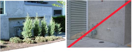
These elements must be located and/or designed to minimize their visibility to the public. Project designers are strongly encouraged to coordinate with applicable service providers early in the design process to determine the best approach to meet these standards. If such elements are mounted in a location visible from the street, pedestrian pathway, shared recreational space, or shared auto courtyards, they must be screened with vegetation and/or integrated into the building’s architecture.
|
Place utility meters in less visible locations. The lower left example is successfully tucked away in a less visible location and screened by vegetation. The right image is poorly executed and prohibited in visible locations (along the sidewalk). Such meters must be coordinated and better integrated with the architecture of the building. |
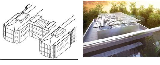
5. Location and Screening of Roof-Mounted Mechanical Equipment.
A. All rooftop mechanical equipment, including air conditioners, heaters, vents, and similar equipment, must be effectively screened from public view at grade and from nearby higher buildings except for solar panels and roof-mounted wind turbines. Screening must be located so as not to interfere with the equipment’s operation.
B. Rooftop mechanical equipment and associated screening features must be set back from the exterior building walls by at least ten feet. Exceptions may be made where the screening element is designed to help meet one or more building design standards of Article 5 of this chapter.
C. For rooftop equipment, all screening devices must be well integrated into the architectural design through such elements as parapet walls, false roofs, roof wells, clerestories, or equipment rooms. Screening walls or unit-mounted screening is allowed but less desirable. Wood must not be used for screens or enclosures. Louvered designs are acceptable if consistent with the building design style. Perforated metal is prohibited.
D. The screening materials must be of material requiring minimal maintenance and must be as tall as the equipment being screened.
E. Locate and/or shield noise-producing mechanical equipment, such as fans, heat pumps, etc., to minimize sounds and reduce impacts at property lines adjacent to residentially zoned properties.
|
The left illustration shows how rooftop mechanical equipment can be located and screened effectively. The right image shows effective location and screening, including side walls and a trellis to screen views from taller surrounding buildings. |
[Ord. 849 § 61, 2024]
19.47.350 Site lighting. Revised 2/25
1. Purpose.
A. Encourage using lighting as an integral design component to enhance buildings, landscaping, or other site features.
B. Encourage night skies’ visibility and reduce the general illumination of the sky in Burien.
C. Reduce horizontal glare and vertical light trespass from a development site onto adjacent parcels.
D. Encourage the judicious use of lighting in conjunction with other security methods to increase site safety.
E. Provide adequate lighting levels in all areas used by pedestrians or automobiles, including building entries, walkways, parking areas, circulation areas, and other open space areas.
2. Design Standards.
A. All public areas should be lighted with minimum and maximum levels as follows:
i. Minimum (for low or non-pedestrian and vehicular traffic areas): 0.5 foot-candles
ii. Moderate (for moderate- or high-volume pedestrian areas): 1–2 foot-candles
iii. Maximum (for high-volume pedestrian areas and building entries): 4 foot-candles
B. Lighting should be provided consistently, with gradual transitions between maximum and minimum lighting levels and between lit and unlit areas. Highly contrasting pools of light and dark areas shall be avoided.
C. Parking lot lighting fixtures should be non-glare and mounted no more than 25 feet above the ground. All fixtures over 15 feet in height shall have a full cut-off shield.
D. Pedestrian-scaled lighting is encouraged in areas of pedestrian activity.
E. Lighting shall enable pedestrians with normal vision to identify a face 15 yards away to promote safety.
F. Site lighting is encouraged to follow the color temperature, timing, intensity, technology, and other recommendations of the International Dark Sky Association and the Illuminating Engineering Society of North America.
G. Site lighting must be installed so that the light is directed downward onto the property upon which it is located. All light sources must be shielded to direct light away from the sky and residential uses. See Figure 19.47.350.2 for an illustration of appropriate light shielding.
Figure 19.47.350.2: Appropriate Light Shielding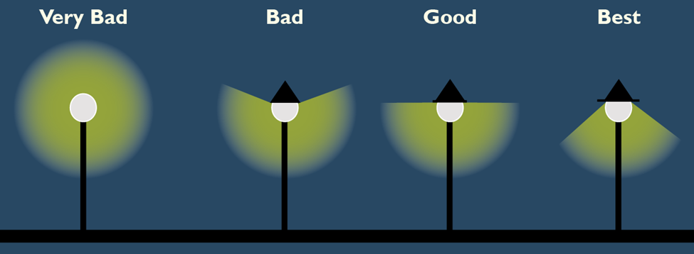
[Ord. 849 § 61, 2024]
Article 5 – Building Design
19.47.400 Building design – Purpose. Revised 2/25
This section provides direction for the design of buildings consistent with the goals and policies of the Burien Comprehensive Plan. See the individual “purpose” statements for each article in this chapter. [Ord. 849 § 61, 2024]
19.47.410 Building design – Applicability. Revised 2/25
Public buildings may be exempted from building massing and articulation standards (see BMC 19.47.420), building details standards (see BMC 19.47.430), building materials provisions (see BMC 19.47.440), and blank wall treatment standards (see BMC 19.47.450) provided design treatments are integrated to meet the following objectives:
1. Enliven the pedestrian environment along the adjacent sidewalks.
2. Incorporate a prominent and inviting entry visible from the street.
3. Building design and materials should evoke a sense of permanence.
4. Site and building design stand out from the surrounding context as a distinct landmark and provide visual interest from all observable scales. [Ord. 849 § 61, 2024]
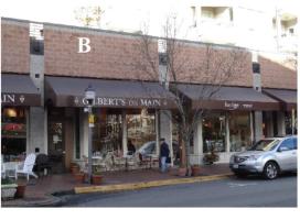
19.47.420 Building massing and articulation. Revised 2/25
1. Purpose. To employ façade articulation techniques that reduce the perceived scale of large buildings and add visual interest from all observable scales.
2. Façade-Articulation. To create a human-scaled pattern, all buildings must include façade-articulation features at maximum-specified intervals. These standards apply to building elevations facing streets and parks.
A. Maximum Facade-Articulation Intervals:
i. Non-residential and mixed-use buildings: 35 feet.
ii. Residential buildings: The width of the dwelling units inside the building (e.g., if the units are 25 feet wide, the façade-articulation must be 25 feet wide).
B. Articulation Features. At least three of the following articulation features must be employed for all buildings over 70 feet wide in compliance with the maximum specified façade-articulation intervals.
i. Use of a window-fenestration pattern.
ii. Use of weather protection features.
iii. Use of vertical piers/columns (applies to all floors of the façade, excluding upper level stepbacks).
iv. Change in roofline with a difference in height, slope or pitch, direction, or shape (such as towers or dormers).
v. Change in building material and/or siding style (applies to all floors of the façade, excluding upper-level stepbacks).
vi. Vertical elements such as a trellis with plants, green walls, and art elements that meet or exceed the standard’s purpose.
vii. Providing vertical building modulation of at least 12 inches in depth if tied to a change in roofline or building material, siding style, or color. Balconies may be used to qualify for this option if they are recessed or projected from the façade by at least 18 inches.
viii. Other design techniques that effectively reinforce a pattern of articulated facades compatible with the building’s surrounding context.
Departures will be considered, provided they meet the standards and the design criteria below. For example, a departure may propose a design with only two articulation features instead of three and/or the articulation features exceed the maximum articulation interval.
|
|
|
|
|
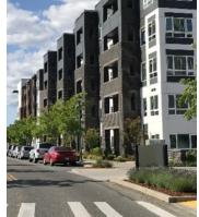
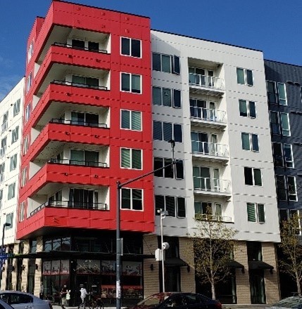
All three buildings above include window patterns, vertical building modulation, and building material/siding style changes. The varying styles of balconies in each also help to articulate the facades. The mixed-use example on the left also uses separate awnings above the storefront to articulate the facade. The middle image also uses roofline modulation. |
||
|
|
|
|
|
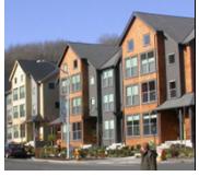
The townhouses on the left use window patterns, vertical building modulation, roofline modulation, and building material/siding style changes. The middle image uses window patterns, awnings, and vertical piers. The right image uses window patterns, vertical building modulation, and weather protection elements. |
||

C. Departure Criteria Associated With Articulation Standards. Proposals must meet the purpose of the standards. The following criteria will determine whether the proposed articulation treatment meets the “purpose”:
i. Consider the type and width of the proposed articulation treatment and how effective it is in meeting the purpose given the building’s current and desired context (per the Ambaum Corridor and Boulevard Park Community Plan).
ii. Consider the applicable block-frontage designation. Non-Pedestrian-Oriented Street block-frontages warrant more flexibility than Pedestrian-Oriented Street block-frontages.
iii. Consider the size and width of the building. Smaller buildings (less than 120 feet wide) warrant greater flexibility than larger buildings.
iv. Consider the quality of façade materials in concert with doors, windows, and other façade features and their ability to add visual interest to the street from a pedestrian scale and more distant observable scales.
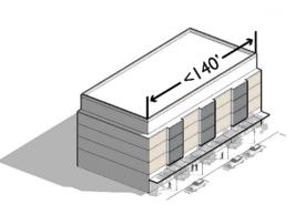
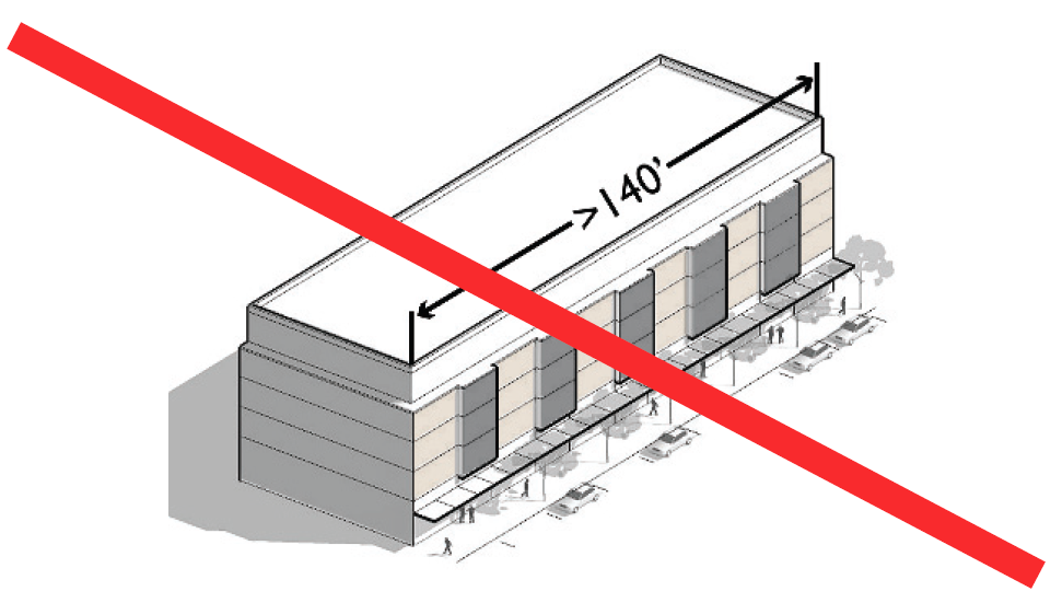
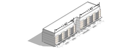
3. Maximum Façade Length. Facades of buildings greater than three stories tall must include at least one of the following features to break up the massing of the building and add visual interest. This standard applies to applicable building elevations longer than 140 feet.
A. Provide vertical building modulation at least six feet deep and 15 feet long. For multi-story buildings, the modulation must extend through at least one-half of the building floors.
B. Use of a contrasting vertical modulated design component featuring all the following:
i. A change in building materials that effectively contrast from the rest of the façade.
ii. Vertical modulation from the rest of the façade by an average of six inches.
C. Façade employs building walls with contrasting articulation that make it appear like multiple distinct buildings. To qualify for this option, these contrasting façades must employ all the following:
i. Different building materials and/or configuration of building materials; and
ii. Contrasting window design (sizes or configurations).
D. Departures to subsections (3)(A) through (3)(C) of this section will be considered, provided the design meets the purpose of the standards. Supplemental consideration for approving alternative designs:
i. Façade Width. The larger the façade, the more substantial articulation/modulation features need to be.
ii. Block-Frontage Designation. Pedestrian-Oriented Street block-frontages warrant the most scrutiny.
iii. The type of articulation treatment and how effective it is in meeting the purpose given the building’s context.
|
Less than 140' long: Meets standard. |
More than 140' long: Does not meet standard. |
|
Building incorporates a courtyard along the façade (technique #1 noted in subsection (3)(A) of this section) to effectively break it up into smaller components: Meets standard. |
|
|
The left building uses technique # 1 (vertical building modulation at least six feet deep and 15 feet wide). The right building uses technique #2 (contrasting vertical modulated design component) together with different window fenestration designs on each side. Both examples are effective in breaking up the perceived scale of the building and adding visual interest. |
|
[Ord. 849 § 61, 2024]
19.47.430 Building details. Revised 2/25
1. Purpose.
A. To encourage the incorporation of design details and small-scale elements into building façades that are attractive at a pedestrian scale.
B. To integrate window design that adds depth, richness, and visual interest to the façade.
2. Façade Details – Pedestrian-Oriented Street Block Frontages and Other Storefront Designs. Storefront buildings on designated Pedestrian-Oriented Street block frontages and other storefront buildings on non-Pedestrian-Oriented Streets that are sited adjacent to the sidewalk must be enhanced with appropriate details. Such buildings must employ at least one detail element from each of the three categories below for each façade articulation interval (see BMC 19.47.420.2).
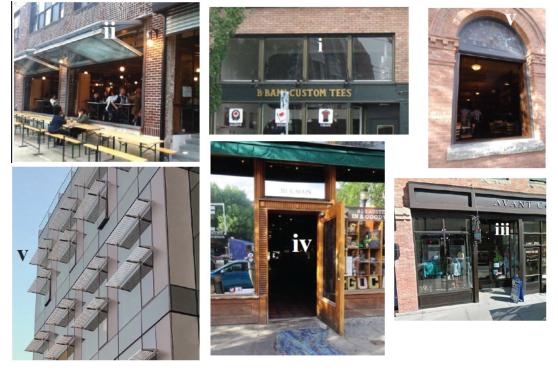
A. Window and/or entry treatment, such as:
i. Transom windows.
ii. Roll-up windows/doors.
iii. Recessed entry.
iv. Decorative door.
v. Other decorative or specially designed window or entry treatments that meet the purpose of the standards.
|
Examples of decorative or specially designed windows and entries. Upper left (ii) = openable storefront window. Center top (i) = transom windows. Upper right (v) = openable window with decorative details. Lower left (v) = decorative window shades. Bottom middle (iv) = Decorative door. Bottom right (iii) = recessed entry. |
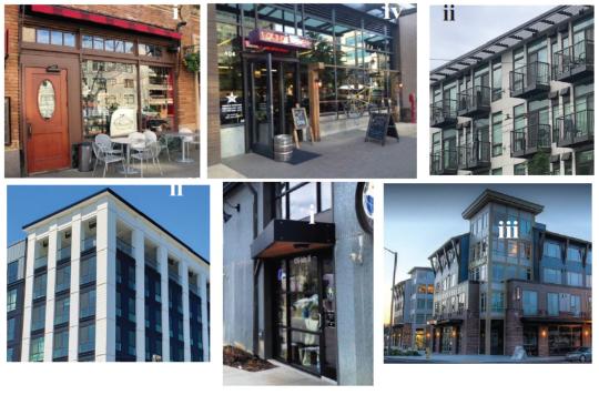
B. Architectural elements and façade attachments, such as:
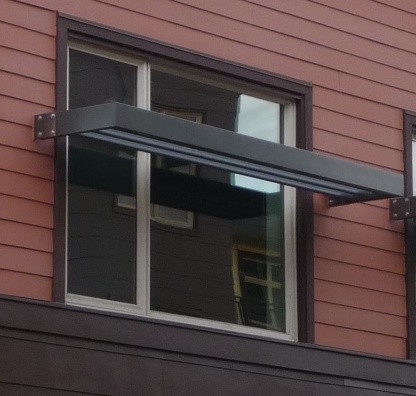
i. Custom-designed weather protection element such as a steel canopy, glass, or retractable awning. Custom-designed cloth awnings may be counted as a detail provided they are constructed of durable, high-quality material.
ii. Decorative rooflines, which could take a variety of forms. It could include an ornamental molding, entablature, frieze, or other roofline device visible from the ground level. If the roofline decoration is in the form of a linear molding or board, then the molding or board must be at least 8 inches wide. Such details could occur on an intermediate floor, where the upper floors are set back beyond the front façade. Examples could also include a modern interpretation of a traditional cornice line with distinct detailing.
iii. Bay windows, trellises, towers, and similar elements.
iv. Other details or elements that meet the standard’s objective(s).
|
Examples of architectural elements and façade attachments. Upper left (i) = retractable awning. Top center (iv) = custom hanging bike rack and repair station integrated as a storefront design element. Upper right (ii) = decorative projecting cornice feature. Lower left (ii) = decorative cornice and top floor. Lower middle (i) = custom decorative canopy. Lower right (iii) = decorative tower. |
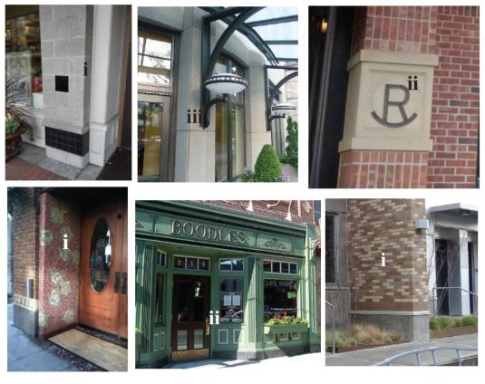
C. Building material details, including:
i. Use of decorative and nondecorative building materials. Examples include the decorative use of brick, tile, or stonework.
ii. Decorative kick-plate, pilaster, base panel, or another similar feature.
iii. Decorative building-mounted light fixtures.
iv. Hand-crafted material, such as special wrought iron or carved wood.
v. Other details that meet the purpose of the standards.
|
Examples of building material details. Upper left (i) = decorative tiling on building column. Top center (iii) = decorative lighting element. Upper right (ii) = decorative medallion integrated into the facade. Lower left (i) = mosaic tile art. Lower middle (ii) = decorative base panel. Lower right (i) = decorative brick design on the column. |
Departures for façade detail standards of subsection (2) of this section will be considered provided the façade (at the overall scale and at the individual articulation scale) meets the purpose of the standards.
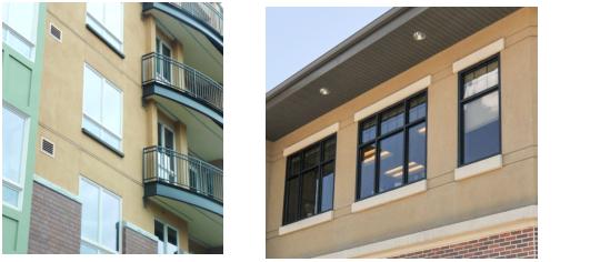
3. Window Design Standards.
A. Window Detailing. The standards herein apply to all elevations of buildings taller than three stories, but only on the street-facing elevation(s) for buildings three stories or less in height. At least one window design from the list below must be incorporated. Portions of building elevations featuring non-residential uses are exempt from this standard.
1. Employ windows that are recessed at least two inches from the façade to add depth and richness to the building.
2. Incorporate trim a minimum of 0.75 inches in depth and at least 3.5 inches wide around windows.
3. Other design treatments to windows that add depth, richness, and visual interest to the façade will be considered.
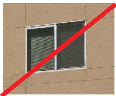
B. Highly reflective glass must not be used on more than ten percent of a building façade or other building elevations facing parks and containing primary building entrances.
|
|
||
|
|
|
All but the lower middle images are recessed by at least two inches from the façade and add a sense of depth and richness to the façade. |
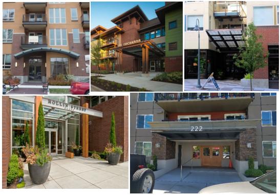
4. Articulated Building Entries. The primary building entrance for an office building, hotel, apartment building, public or community-based facility, or other multi-story commercial building must be designed as a clearly defined and demarcated standout architectural feature of the building. Such entrances must be easily distinguishable from regular storefront entrances in the building. Such entries must be scaled proportional to the building. See Figure 19.47.430.4 for good examples.
|
|
5. Construction Date Plaque. For Downtown Urban Center developments, the year of building construction must be noted by a permanent cast metal plaque installation attached to the building or a stone or masonry set integral with other masonry on the front building elevation facing the principal street. The year of construction is to be noted by numbers not less than six inches high. Other information associated with the building that may have future historic interest may be included. [Ord. 849 § 61, 2024]
19.47.440 Building materials. Revised 2/25
1. Building Materials – Purpose.
A. To encourage the use of durable, high-quality, and urban building materials that minimize maintenance costs and provide visual interest from all observable vantage points.
B. To promote the use of a distinctive mix of materials that helps to articulate façades and lends a sense of depth and richness to the buildings.
C. To place the highest priority on the first floor in the quality and detailing of materials at the pedestrian scale.
2. Building Materials Applicability. The standards herein apply to the following buildings:
A. Buildings at designated high visibility street corners per BMC 19.47.290.
B. Buildings along designated Pedestrian-Oriented Street block frontages and other buildings designed as storefronts adjacent to sidewalks that are more than three stories in height.
3. Building Materials – Special Conditions and Limitations for the Use of Certain Cladding Materials.
A. Concrete block (a.k.a. Concrete Masonry Unit or CMU) may be used as a secondary cladding material (no more than 1/3 of total façade cladding) on all building façades and other building elevations facing parks, pedestrian-oriented spaces, and containing primary building entrances provided it is incorporated with other permitted materials.
Departures will be considered for alternative designs that use concrete block as the primary, but not the only, cladding material, provided the design incorporates a combination of textures and/or colors to add visual interest. For example, combining split or rock-façade units with smooth blocks can create distinctive patterns. The figures below illustrate acceptable concrete block use/designs.
|
Building 1 uses smooth-faced CMU as a contrasting feature that helps to highlight the main building entry. The simple design helps to add emphasis to the doors, canopy, and decorative sconce lights. |
Building 2 illustrates an acceptable departure example, as CMU is used as the primary cladding material. Note the use of beige split-façade CMUs above each of the awnings coupled with the use of smooth-faced gray CMUs on the vertical columns (which employ black accent tiles for added interest). |
B. Metal siding may be used on all street-facing building elevations provided it complies with the following standards:
i. It must feature visible corner molding and trim, not extend to the ground level of non-residential and mixed-use buildings, and is no lower than two feet above grade for residential buildings. Masonry, concrete, or other durable material must be incorporated between the metal siding and the ground plane.
ii. Metal siding must be factory-finished, with a matte, non-reflective surface.
Departures will be considered provided the material’s integration and overall façade composition meet standards.
|
The upper building examples successfully use metal siding more as an accent element to help articulate the façade. Metal siding is the primary material for the lower building examples, both of which integrate subtle changes in color to go with articulation features and design details. |
C. Standards for the Use of Exterior Insulation and Finish System (EIFS). Such material/finishes may be used when it complies with the following:
i. EIFS is limited to no more than 20% of the total façade area and may not be the primary cladding material on non-residential and mixed-use buildings.
ii. EIFS must feature a smooth or sand finish only.
iii. EIFS must be trimmed in wood, masonry, or other material and must be sheltered from weather by roof overhangs or other methods.
iv. EIFS must not be used on the ground floor of facades containing non-residential uses.
Departures will be considered provided the material’s integration and overall façade composition meet the purpose of the standards.
|
|
|
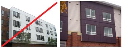
The upper building examples mix EIFS with brick and other materials and integrate trim details around windows to add a sense of depth to the façade. The lower left building uses EIFS in between the window and sidewalk – this design is prohibited. The lower right building uses EIFS as the primary siding material, which is prohibited. |
D. Cementitious wall board paneling/siding may be used, provided it meets the following provisions:
i. Cement board paneling/siding may not be used on ground-level facades containing non-residential uses.
ii. Where cement board paneling/siding is the dominant siding material, the design must integrate a mix of colors and/or textures that are articulated and consistent with windows, balconies, and modulated building surfaces and are balanced with façade details that add visual interest from the ground-level and adjacent buildings.
Departures will be considered provided the material’s integration and overall façade composition meet the purpose of the standards.
|
The above buildings use cementitious wall board in different textures and colors to help articulate the façade. |
|
The wallboard panels covering a large area in a single color in the left building would not meet the purpose of the standards. The right building’s design is a better example and combines larger panels (dark maroon color) with horizontal wall board siding (beige color) as effective articulation features. |
[Ord. 849 § 61, 2024]
19.47.450 Blank wall treatment. Revised 2/25
1. Blank Wall Treatment Purpose.
A. To avoid untreated blank walls.
B. To retain and enhance the character of Burien’s streetscapes.
2. Blank Wall Definition. “Blank wall” means a ground floor wall or portion of a ground floor wall over 10 feet in height and a horizontal length greater than 15 feet and does not include a transparent window or door.
Figure 19.47.450.2
Blank Wall Definition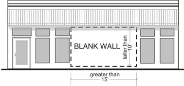
3. Blank Wall Treatment Standards. Untreated blank walls adjacent to a public street, pedestrian-oriented space, common usable open space, or pedestrian pathway are prohibited. Methods to treat blank walls can include:
A. Display windows at least 16 inches in depth to allow changeable displays. Tack-on display cases (see Figure 19.47.450.3 below) do not qualify as blank wall treatment.
B. Landscape planting bed at least five feet deep or a raised planter bed at least two feet high and three feet deep in front of the wall with planting materials that are sufficient to obscure or screen at least 60% of the wall’s surface within three years.
C. Installing a vertical trellis in front of the wall with climbing vines or plant materials.
D. Installing a mural. Commercial advertisements are not permitted on such murals.
E. Special building detailing that adds visual interest at a pedestrian scale. Such detailing must use a variety of surfaces.
For large visible blank walls, a variety of treatments may be required to meet the purpose of the standards.
|
Buildings A–C feature acceptable treatments, including a combination of high-quality materials and landscaping (A), decorative lighting/sculptural elements (B), and special building detailing (C). The display cases in Building D don’t meet the 16" depth requirement, nor do they meet the purpose of the standards. |
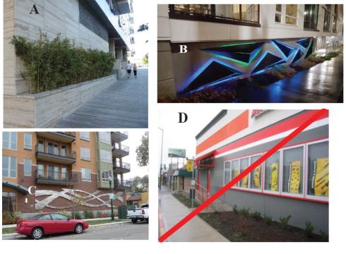
4. Firewalls. Firewalls along property lines are exempt from the above standards, but where they are visible to the public (from the adjacent street), they must be designed to provide visual interest from all observable distances. Examples may include the use of varying materials, textures, and/or colors, the use of green or living walls, and/or the use of modulated building walls to form design patterns.
Murals are also encouraged as a firewall treatment. Commercial advertisements are not permitted on such murals.
|
The left images use a combination of paint bands and climbing vines to enhance the appearance of this large, exposed firewall. The building in the right image uses simple scoring patterns and changes in materials and color on part of the top floor to add visual interest. |
|
|
|
Plain-gray concrete block firewalls such as this are prohibited when visible from the street. |
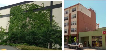
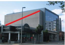
[Ord. 849 § 61, 2024]
Article 6 – Air and Noise Mitigation
19.47.500 Air and noise mitigation purpose. Revised 2/25
To reduce the long-term health impacts of air and noise pollution on sensitive populations in areas with known sources of air and noise pollution, such as limited-access freeways and airport flight paths. [Ord. 849 § 61, 2024]
19.47.510 Flight path impact area. Revised 2/25
1. Applicability. The standards of this section apply to sites located in the 65 DNL noise contour for SeaTac Airport maintained by the Port of Seattle.
2. Air Filtration. Building ventilation and filtration systems rated to remove ultrafine particulate matter (diameter less than 100 nanometers (nm) or 0.1 microns (µm)) from indoor air are required.
3. Outdoor Space Design. Public gathering spaces or semi-private common open spaces shall include at least two of the following noise-blocking or -masking features:
A. Overhead shelters.
B. Water features with running water.
C. Leaves that rustle.
D. Wind chimes.
E. Landscape design:
i. Preserve and enhance natural landscapes and tree canopy to minimize air pollution impacts. Maximize green stormwater infrastructure, bioremediation, and tree canopy techniques (e.g., long-needle conifers) to capture and treat particulate matter in the air and in stormwater run-off, while considering human use and safety of the landscape areas.
ii. Use drought-tolerant and native or hardy, climate-ready, adapted species. [Ord. 849 § 61, 2024]
19.47.520 Freeway impact area. Revised 2/25
1. Applicability. The standards of this section apply within 500 feet of limited-access freeways.
2. Air Filtration: Building ventilation and filtration systems rated to remove fine particulate matter (0.3 microns (µm)) from indoor air are required.
3. Site Planning. New development must employ the following site planning techniques to the extent feasible:
A. Parcels located immediately adjacent to a limited-access freeway are required to plant a double row of long-needle conifers allowing no line-of-sight when mature to trap particulate matter.
B. Locate sensitive uses as far away as feasible from the air/noise pollution source, and/or use screening/shielding techniques, such as:
i. Place noise-compatible land uses such as parking lots, maintenance facilities, and utility areas between the road and the residences or noise-sensitive uses.
ii. Where possible, place residential uses and major outdoor public spaces at least 500' from the freeway or as far away from the freeway as possible.
iii. Use berms or buildings with non-sensitive uses as noise shields by locating them parallel to the road and closer to the road than more sensitive uses.
iv. Plant trees and/or vegetation between sensitive uses and pollution sources, if feasible.
v. Locate residences in topographically low points that are naturally low noise pockets if they exist.
vi. Orient courtyards, shared open spaces, and balconies away from the noise/air pollution source where feasible.
vii. Locate residences or other sensitive uses on upper floors of buildings, if feasible.
C. Buildings should be oriented to maximize airflow, employing the following techniques:
i. Variety of building shapes and orientations;
ii. Variety of building heights.
D. If applicable and feasible, phase redevelopment so that any residential uses near the highway are built last.
4. Building Design.
A. Operable windows, balconies, building air intakes, and courtyard spaces must be located as far away from the pollution source as feasible.
B. Bedrooms must be located on sides of buildings farthest from the noise source(s), if feasible.
5. Landscape Design.
A. Preserve and enhance natural landscapes and tree canopy to minimize air pollution impacts. Maximize green stormwater infrastructure, bioremediation, and tree canopy techniques (e.g., long-needle conifers) to capture and treat particulate matter in the air and in stormwater run-off, while considering human use and safety of the landscape areas.
B. Use drought-tolerant and native or hardy, climate-ready, adapted species. [Ord. 849 § 61, 2024]